differential MITSUBISHI SPYDER 1990 Service Repair Manual
[x] Cancel search | Manufacturer: MITSUBISHI, Model Year: 1990, Model line: SPYDER, Model: MITSUBISHI SPYDER 1990Pages: 2103, PDF Size: 68.98 MB
Page 36 of 2103
Lubrication and
GENERAL Lubricants and Lubricant Capacities Table
Use of fuels containing alcohol is not recommended
unless the nature of the blend can be determined
as being satisfactory.
Gasohol
A mixture of 10% ethanol (grain alcohol)
and 90% unleaded gasoline may be used in your
car.
If problems are experienced as a result
of using gasohol, it is recommended that the car
be operated on gasoline.
Methanol Do not use gasolines containing
methanol (wood alcohol). Use of this type of alcohol
can result in vehicle performance deterioration and
damage critical parts in the fuel system compo-
nents. Fuel system damage and performance prob-
lems, resulting from the use of gasolines containin g
methanol, may not be covered by the new car war-
ranty.
Gasolines containing
Ether)
Unleaded gasoline containing 15% or
may be used in car. Fuel containing MTBE
over 15% vol. may cause reduced engine perfor-
mance and produce vapor lock or hard starting.
MATERIALS
TO FUEL
Indiscriminate use of fuel system -cleaning’
should be avoided. Many of these materials in-
tended for gum and varnish removal
highly active solvents or similar ingredients that
can be harmful to gasket and diaphragm materials
used in fuel system component
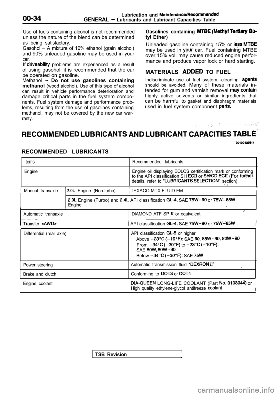
RECOMMENDED LUBRICANTS
Items
Engine
Recommended lubricants
Engine oil displaying EOLCS certification mark or c onforming
to the API classification SH or (For
details, refer to section)
Manual transaxle Engine (Non-turbo) TEXACO MTX FLUID FM I
Engine (Turbo) and API classification SAE or
Engine,
Automatic transaxle DIAMOND ATF SP or equivalent
TSB Revision
Transfer API classification SAE or
Differential (rear axle)API classification or higher
Above SAE
From to
SAE
Below SAE
Power steering
Brake and clutch Automatic transmission fluid
Conforming to or
Engine coolant LONG-LIFE COOLANT (Part or
High quality ethylene-glycol antifreeze I
Page 37 of 2103
GENERAL Recommended Lubricants and Lubricant Table
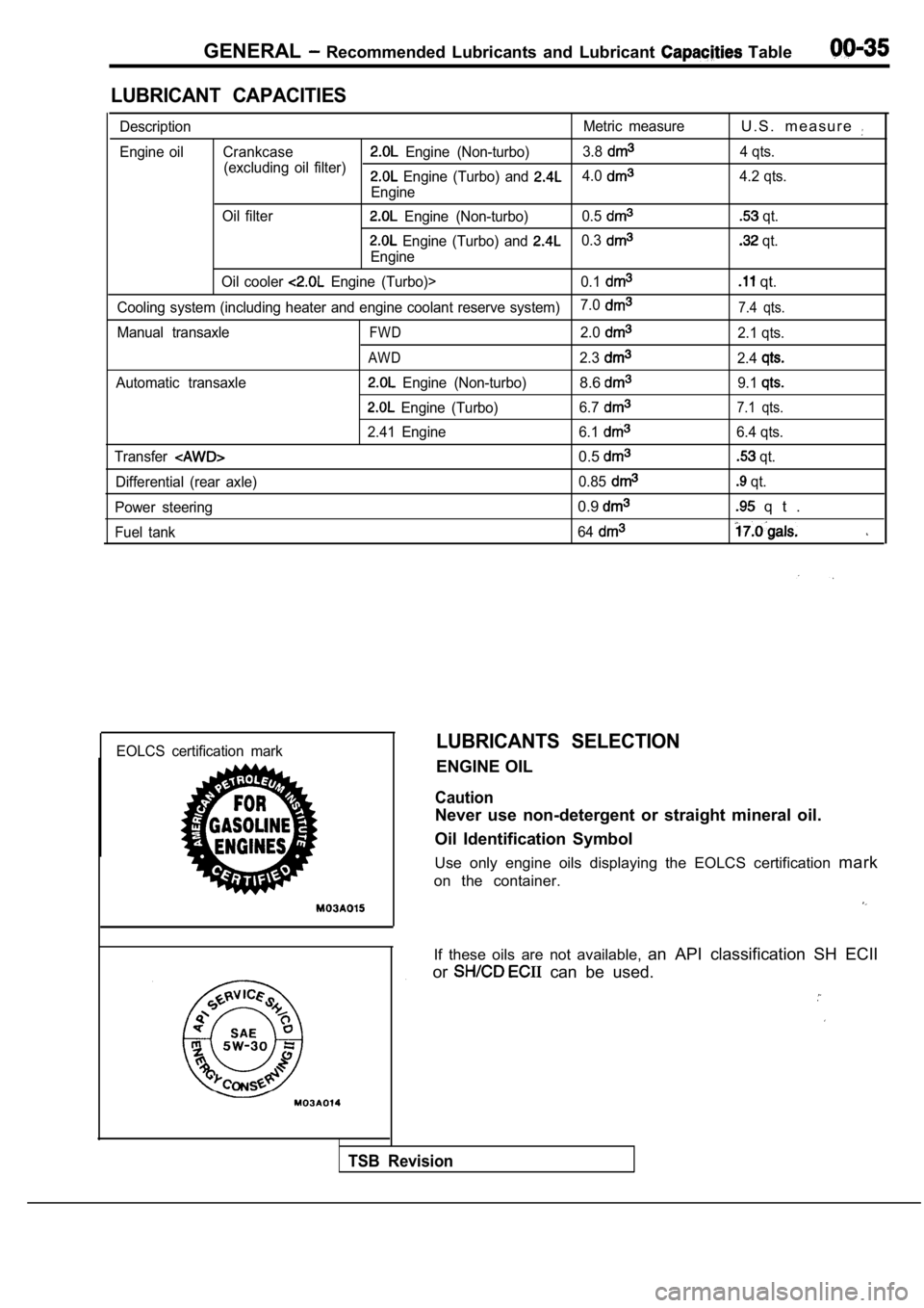
LUBRICANT CAPACITIES
DescriptionMetric measureU . S . m e a s u r e
Engine oil Crankcase Engine (Non-turbo)3.8
(excluding oil filter) 4 qts. Engine (Turbo) and 4.0
Engine4.2 qts.
Oil filter
Engine (Non-turbo) 0.5 qt.
Engine (Turbo) and 0.3
Engine
qt.
Oil cooler
Engine (Turbo)> 0.1 qt.
Cooling system (including heater and engine coolant reserve system)7.07.4 qts.
Manual transaxleFWD2.02.1 qts.
AWD2.32.4
Automatic transaxle Engine (Non-turbo)8.69.1
Engine (Turbo)
6.77.1 qts.
2.41 Engine 6.16.4 qts.
Transfer
0.5 qt.
Differential (rear axle) 0.85
qt.
Power steering
0.9 q t .
Fuel tank 64
EOLCS certification markLUBRICANTS SELECTION
ENGINE OIL
Caution
Never use non-detergent or straight mineral oil.
Oil Identification Symbol
Use only engine oils displaying the EOLCS certifica tion mark
on the container.
If these oils are not available, an API classification SH ECII
or
can be used.
TSB Revision
Page 58 of 2103
GENERAL Main Sealant and Adhesive Table
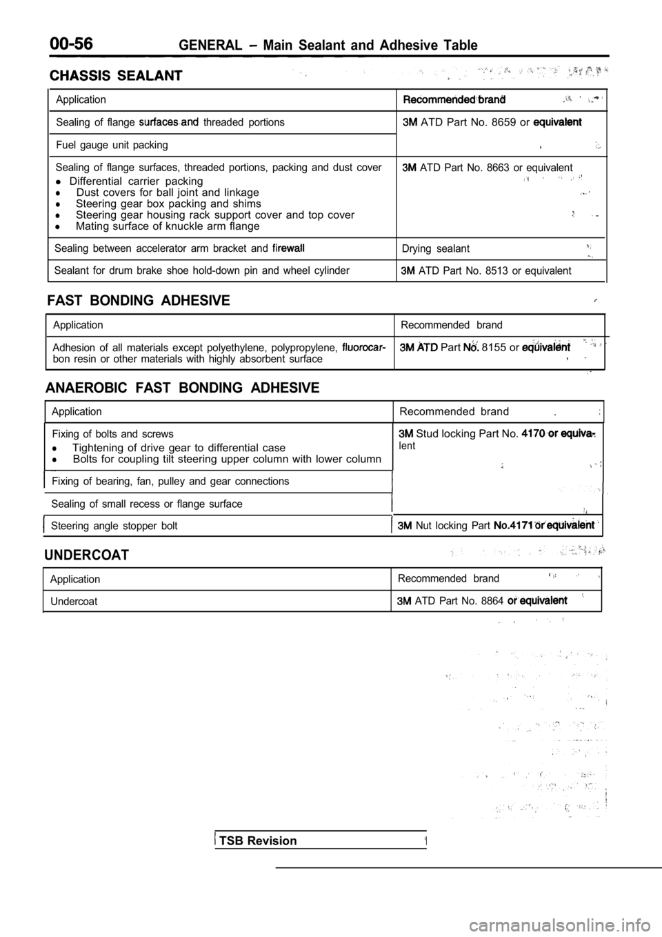
Application
Sealing of flange threaded portions ATD Part No. 8659 or
Fuel gauge unit packing,
Sealing of flange surfaces, threaded portions, packing and dust cover ATD Part No. 8663 or equivalent
l Differential carrier packing
lDust covers for ball joint and linkage
lSteering gear box packing and shims
lSteering gear housing rack support cover and top co ver
lMating surface of knuckle arm flange
Sealing between accelerator arm bracket and Drying sealant
Sealant for drum brake shoe hold-down pin and wheel cylinder ATD Part No. 8513 or equivalent
FAST BONDING ADHESIVE
Application Recommended brand
Adhesion of all materials except polyethylene, poly propylene,
Part 8155 or
bon resin or other materials with highly absorbent surface,
ANAEROBIC FAST BONDING ADHESIVE
ApplicationRecommended brand.
Fixing of bolts and screws
lTightening of drive gear to differential case
lBolts for coupling tilt steering upper column with lower column
Fixing of bearing, fan, pulley and gear connections
Sealing of small recess or flange surface
Steering angle stopper bolt Nut locking Part
Stud locking Part No.
lent
UNDERCOAT
Application Undercoat Recommended brand
ATD Part No. 8864
TSB Revision‘I
Page 77 of 2103
ENGINE Engine Assembly
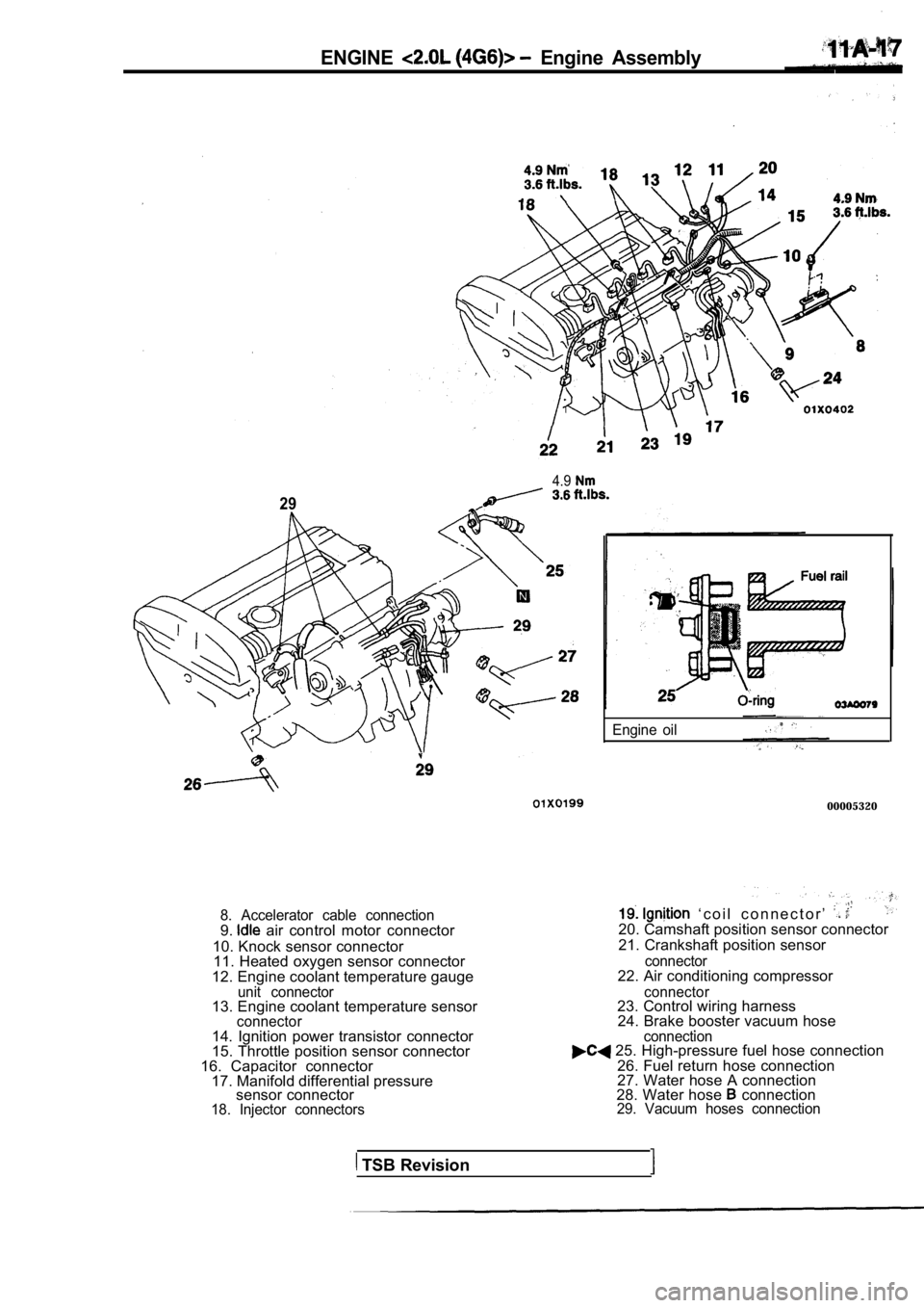
4.9
29
8. Accelerator cable connection9. air control motor connector
10. Knock sensor connector 11. Heated oxygen sensor connector
12. Engine coolant temperature gauge
unit connector13. Engine coolant temperature sensorconnector
Engine oil
00005320
‘ c o i l c o n n e c t o r ’ 20. Camshaft position sensor connector
21. Crankshaft position sensor
connector22. Air conditioning compressor
connector23. Control wiring harness 24. Brake booster vacuum hose .
14. Ignition power transistor connector
15. Throttle position sensor connector
16. Capacitor connector 17. Manifold differential pressure sensor connector
18. Injector connectors connection
25. High-pressure fuel hose connection
26. Fuel return hose connection
27. Water hose A connection
28. Water hose
connection29. Vacuum hoses connection
TSB Revision
Page 91 of 2103
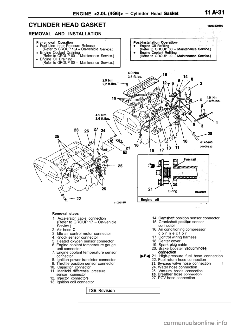
ENGINE Cylinder Head
CYLINDER HEAD GASKET
REMOVAL AND INSTALLATION
Pre-removal Operationl Fuel Line Inner Pressure Release(Refer to GROUP On-vehiclel Engine Coolant Draining(Refer to GROUP 00 Maintenance Service.)l Engine Oil Draining(Refer to GROUP 00 Maintenance Service.)
3.62.9 Nm
2.2
4.9 Nm
220 1
Removal steps
1. Accelerator cable connection(Refer to GROUP 17 On-vehicleService.)2. Air hose 3. Idle air control motor connector
4. Knock sensor connector
5. Heated oxygen sensor connector
6. Engine coolant temperature gauge
unit connector
7. Engine coolant temperature sensor
connector8. Ignition power transistor connector
9. Throttle position sensor connector
10. Capacitor connector
11. Manifold differential pressure sensor connector
12. Injector connectors
13. Ignition coil connector Engine oil
,
21
14. position sensor connector
15. Crankshaft sensor
16. Air conditioning compressor
c o n n e c t o r
17. Control wiring harness
18. Center cover
19. Spark
cable
20. Brake booster
21. High-pressure fuel hose connection 22. Fuel return hose connection
23. By-pass valve hose connection
24. Water hose connection25. Vacuum hoses connection26.Breather hose 27. PCV hose connection
TSB Revision
Page 284 of 2103
.
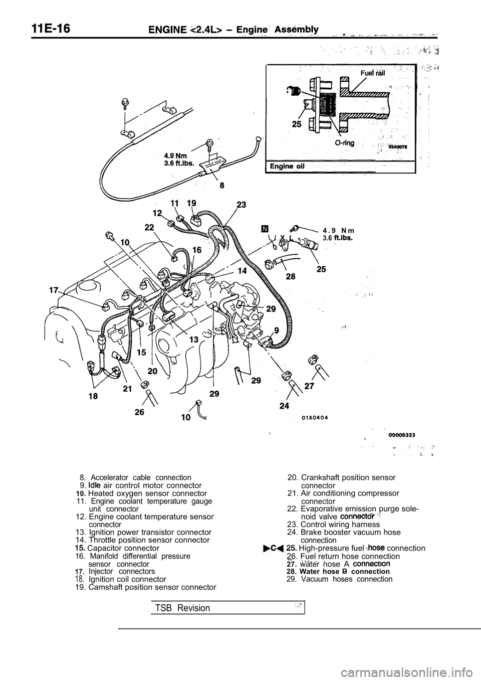
4 . 9 N m
\ / X L - -3.6
. .
8. Accelerator cable connection9. air control motor connector
10. Heated oxygen sensor connector
11. Engine coolant temperature gauge
unit connector
12. Engine coolant temperature sensorconnector13. Ignition power transistor connector
14. Throttle position sensor connector
Capacitor connector16. Manifold differential pressure
20. Crankshaft position sensor
connector21. Air conditioning compressor
connector22. Evaporative emission purge sole-
noid valve
23. Control wiring harness
24. Brake booster vacuum hose
connection High-pressure fuel connection
26. Fuel return hose connection --
. .. .
17.18.
sensor connector
Injector connectors
Ignition coil connector
19. Camshaft position sensor connector 27.
water nose A 28. Water hose connection29. Vacuum hoses connection
TSB Revision
Page 520 of 2103
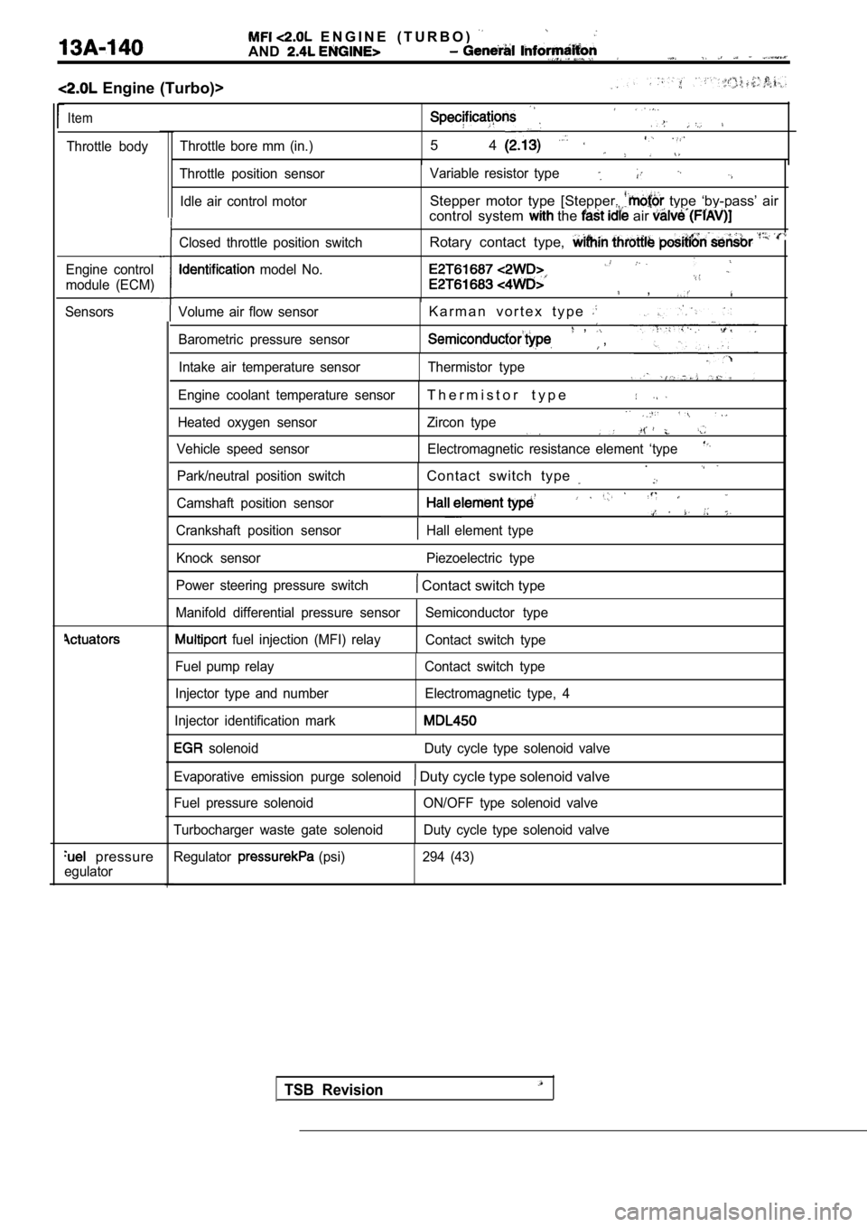
E N G I N E ( T U R B O )
AND
Engine (Turbo)>
Item
Throttle bodyThrottle bore mm (in.)5 4
Engine control
module (ECM)
Sensors
pressure
egulator
Volume air flow sensor
Barometric pressure sensorK a r m a n v o r t e x t y p e , ,
Intake air temperature sensor Thermistor type
Engine coolant temperature sensor
T h e r m i s t o r t y p e
Heated oxygen sensor Zircon type
Vehicle speed sensor Electromagnetic resistance elem ent ‘type
Park/neutral position switchContact switch type .
Camshaft position sensor
Crankshaft position sensorHall element type
Throttle position sensor
Idle air control motor Variable resistor type
Stepper motor type [Stepper. type ‘by-pass’ air
control system
the air
Closed throttle position switch
model No.
Rotary contact type,
,
Knock sensor Piezoelectric type
Power steering pressure switch
Contact switch type
Manifold differential pressure sensor Semiconductor type
fuel injection (MFI) relay
Contact switch type
Fuel pump relay
Injector type and number
Injector identification mark Contact switch type
Electromagnetic type, 4
solenoid Duty cycle type solenoid valve
Evaporative emission purge solenoid
Duty cycle type solenoid valve
Fuel pressure solenoid
Turbocharger waste gate solenoid ON/OFF type solenoid valve
Duty cycle type solenoid valve
Regulator
(psi) 294 (43)
TSB Revision
Page 522 of 2103
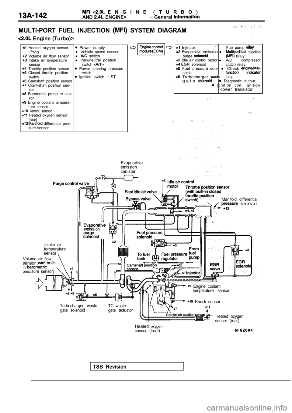
E N G I N E ( T U R B O )
AND
ENGINE> General . .
MULTI-PORT FUEL INJECTION SYSTEM DIAGRAM
Engine (Turbo)>
Heated oxygen sensor(front) Volume air flow sensor Intake air temperaturesensor Throttle position sensor Closed throttle positionswitch Camshaft position sensor Crankshaft position sen-sor Barometric pressure sen-sor Engine coolant tempera- ture sensor
Knock sensor Heated oxygen sensor(rear) differential pres-
sure sensor
Power supply
l Vehicle speed sensor
l
switch
l Park/neutral position
switch
Power steering pressureswitch Ignition switch ST
Enginecontrol Injector . Fuel pump
Evaporative emission l injectionpurge relay Idle air control motor lA/Ccompressor solenoid clutch relay Fuel pressure sole-
l C h e c knoide T u r b o c h a r g e r lampg a t e Diagnostic output I g n i t i o n c o i l , i g n i t i o n cower transistor
,
Evaporative
emission
canister
TSB Revision
Manifold differential s e n s o r
IIion. .
Intake air
temperature
sensor
Volume air flow
sensor . insure sensor) IIpres:
Engine coolant temperature sensor
Turbocharger waste gate solenoid TC waste
gate actuator
Knock sensor
Heated oxygen
sensor (rear)
Heated oxygensensor (front)
Page 523 of 2103
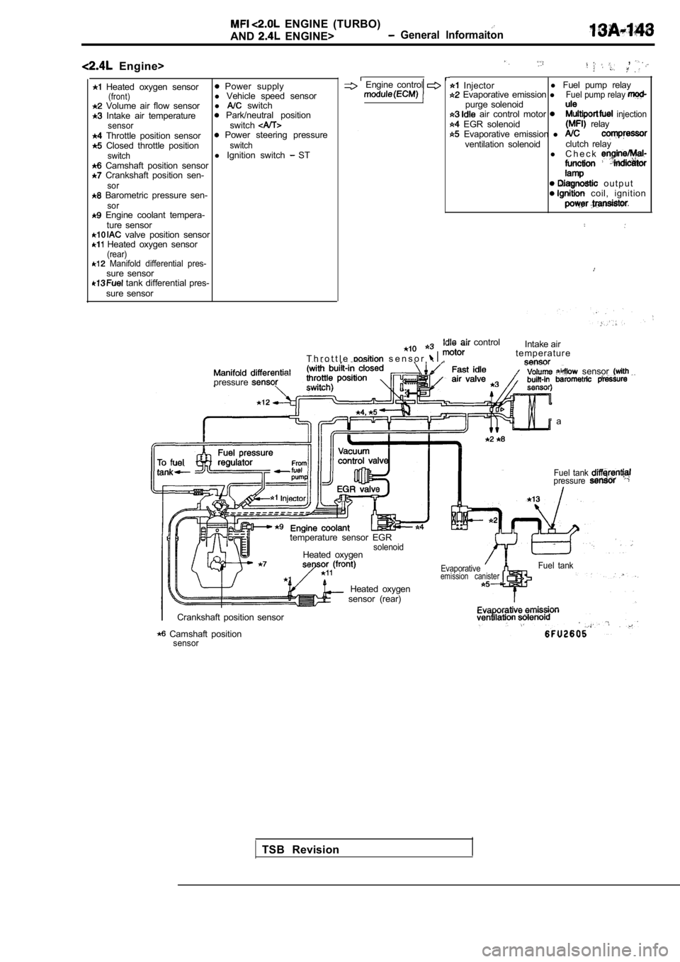
ENGINE (TURBO)
AND ENGINE> General lnformaiton
Engine>
Heated oxygen sensor Power supply(front)l Vehicle speed sensor Volume air flow sensor l switch Intake air temperature Park/neutral positionsensorswitch Throttle position sensor Power steering pressure Closed throttle positionswitch
switchl Ignition switch ST Camshaft position sensor Crankshaft position sen-sor Barometric pressure sen-sor Engine coolant tempera-
ture sensor
valve position sensor Heated oxygen sensor(rear) Manifold differential pres-sure sensor tank differential pres-
sure sensor
,
Engine control Injector l
Fuel pump relay Evaporative emission lFuel pump relay purge solenoid air control motor injection EGR solenoid relay Evaporative emission l ventilation solenoid clutch relay
l C h e c k
o u t p u t coil, ignition
T h r o t t l e s e n s o r ,
control
Intake air
t e m p e r a t u r e
. . . sensor pressure
a
temperature sensor EGR
solenoidHeated oxygen
Fuel tank pressure
sensor (rear) Heated oxygen
Evaporativeemission canisterFuel tank
Crankshaft position sensor
Camshaft positionsensor
TSB Revision
Page 528 of 2103
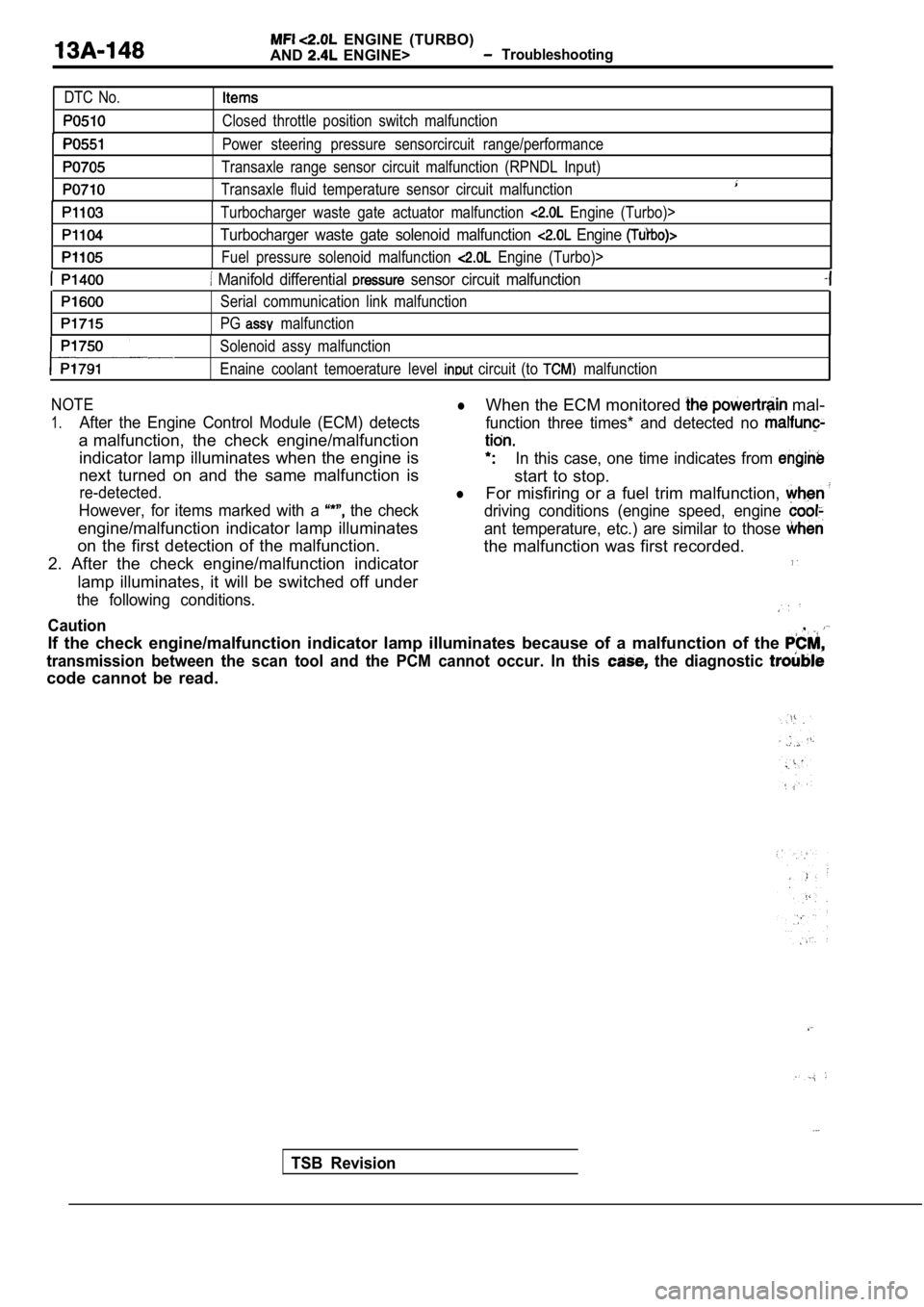
ENGINE (TURBO)
AND
ENGINE> Troubleshooting
DTC No.
Closed throttle position switch malfunction
Power steering pressure sensorcircuit range/perfor mance
Transaxle range sensor circuit malfunction (RPNDL Input)
Transaxle fluid temperature sensor circuit malfunct ion
Turbocharger waste gate actuator malfunction Engine (Turbo)>
Turbocharger waste gate solenoid malfunction Engine
Fuel pressure solenoid malfunction Engine (Turbo)>
Manifold differential sensor circuit malfunction
Serial communication link malfunction
PG
malfunction
Solenoid assy malfunction
Enaine coolant temoerature level
circuit (to malfunction
NOTElWhen the ECM monitored mal-
1.After the Engine Control Module (ECM) detects function three times* and detected no
a malfunction, the check engine/malfunction
indicator lamp illuminates when the engine isIn this case, one time indicates from
next turned on and the same malfunction is
start to stop.
re-detected.lFor misfiring or a fuel trim malfunction,
However, for items marked with a the checkdriving conditions (engine speed, engine
engine/malfunction indicator lamp illuminatesant temperature, etc.) are similar to those
on the first detection of the malfunction. the malfunction was first recorded.
2. After the check engine/malfunction indicator
lamp illuminates, it will be switched off under
the following conditions.
Caution,
If the check engine/malfunction indicator lamp illu minates because of a malfunction of the
transmission between the scan tool and the PCM cann ot occur. In this the diagnostic
code cannot be read.
TSB Revision