engine MITSUBISHI SPYDER 1990 Service Repair Manual
[x] Cancel search | Manufacturer: MITSUBISHI, Model Year: 1990, Model line: SPYDER, Model: MITSUBISHI SPYDER 1990Pages: 2103, PDF Size: 68.98 MB
Page 3 of 2103
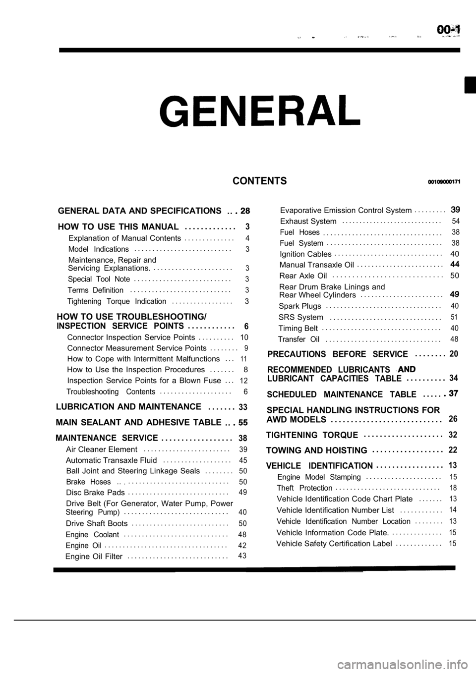
CONTENTS
GENERAL DATA AND SPECIFICATIONS. .
HOW TO USE THIS MANUAL. . . . . . . . . . . . .3
Explanation of Manual Contents. . . . . . . . . . . . . .4
Model Indications
. . . . . . . . . . . . . . . . . . . . . . . . . . .3
Maintenance, Repair and
Servicing Explanations. . . . . . . . . . . . . . . . . . . . . . .
3
Special Tool Note. . . . . . . . . . . . . . . . . . . . . . . . . . .3
Terms Definition. . . . . . . . . . . . . . . . . . . . . . . . . . . .3
Tightening Torque Indication. . . . . . . . . . . . . . . . .3
HOW TO USE TROUBLESHOOTING/
INSPECTION SERVICE POINTS. . . . . . . . . . . .6
Connector Inspection Service Points
. . . . . . . . . .10
Connector Measurement Service Points . . . . . . . .9
How to Cope with Intermittent Malfunctions . . .11
How to Use the Inspection Procedures
. . . . . . .
8
Inspection Service Points for a Blown Fuse . . .
12
Troubleshooting Contents. . . . . . . . . . . . . . . . . . . .6
LUBRICATION AND MAINTENANCE . . . . . . .33
MAIN SEALANT AND ADHESIVE TABLE
. .
MAINTENANCE SERVICE. . . . . . . . . . . . . . . . . .38
Air Cleaner Element. . . . . . . . . . . . . . . . . . . . . . . .39
Automatic Transaxle Fluid
. . . . . . . . . . . . . . . . . . .45
Ball Joint and Steering Linkage Seals
. . . . . . . .50
Brake Hoses.... . . . . . . . . . . . . . . . . . . . . . . . . . . .50
Disc Brake Pads. . . . . . . . . . . . . . . . . . . . . . . . . . . .49
Drive Belt (For Generator, Water Pump, Power
Steering Pump). . . . . . . . . . . . . . . . . . . . . . . . . . . . .40
Drive Shaft Boots
. . . . . . . . . . . . . . . . . . . . . . . . . . .50
Engine Coolant. . . . . . . . . . . . . . . . . . . . . . . . . . . . .48
Engine Oil. . . . . . . . . . . . . . . . . . . . . . . . . . . . . . . . . .42
Engine Oil Filter. . . . . . . . . . . . . . . . . . . . . . . . . . . .43
Evaporative Emission Control System . . . . . . . . .
Exhaust System. . . . . . . . . . . . . . . . . . . . . . . . . . . . .54
Fuel Hoses. . . . . . . . . . . . . . . . . . . . . . . . . . . . . . . . .38
Fuel System. . . . . . . . . . . . . . . . . . . . . . . . . . . . . . . .38
Ignition Cables. . . . . . . . . . . . . . . . . . . . . . . . . . . . . .
40
Manual Transaxle Oil . . . . . . . . . . . . . . . . . . . . . . . .
Rear Axle Oil. . . . . . . . . . . . . . . . . . . . . . . . . . . .
50
Rear Drum Brake Linings and
Rear Wheel Cylinders . . . . . . . . . . . . . . . . . . . . . . .
Spark Plugs. . . . . . . . . . . . . . . . . . . . . . . . . . . . . . . .40
SRS System . . . . . . . . . . . . . . . . . . . . . . . . . . . . . . .51
Timing Belt. . . . . . . . . . . . . . . . . . . . . . . . . . . . . . . . .40
Transfer Oil. . . . . . . . . . . . . . . . . . . . . . . . . . . . . . . .48
PRECAUTIONS BEFORE SERVICE. . . . . . . .20
RECOMMENDED LUBRICANTS
LUBRICANT CAPACITIES TABLE. . . . . . . . . .34
SCHEDULED MAINTENANCE TABLE. . . . .
SPECIAL HANDLING INSTRUCTIONS FOR
AWD MODELS . . . . . . . . . . . . . . . . . . . . . . . . . . . .
26
TIGHTENING TORQUE. . . . . . . . . . . . . . . . . . . .32
TOWING AND HOISTING . . . . . . . . . . . . . . . . . .22
VEHICLE IDENTIFICATION. . . . . . . . . . . . . . . . .13
Engine Model Stamping. . . . . . . . . . . . . . . . . . . . .15
Theft Protection. . . . . . . . . . . . . . . . . . . . . . . . . . . . .18
Vehicle Identification Code Chart Plate
. . . . . . .13
Vehicle Identification Number List. . . . . . . . . . . .14
Vehicle Identification Number Location. . . . . . . .13
Vehicle Information Code Plate.. . . . . . . . . . . . . .15
Vehicle Safety Certification Label
. . . . . . . . . . . . .15
Page 5 of 2103
GENERAL How to Use This
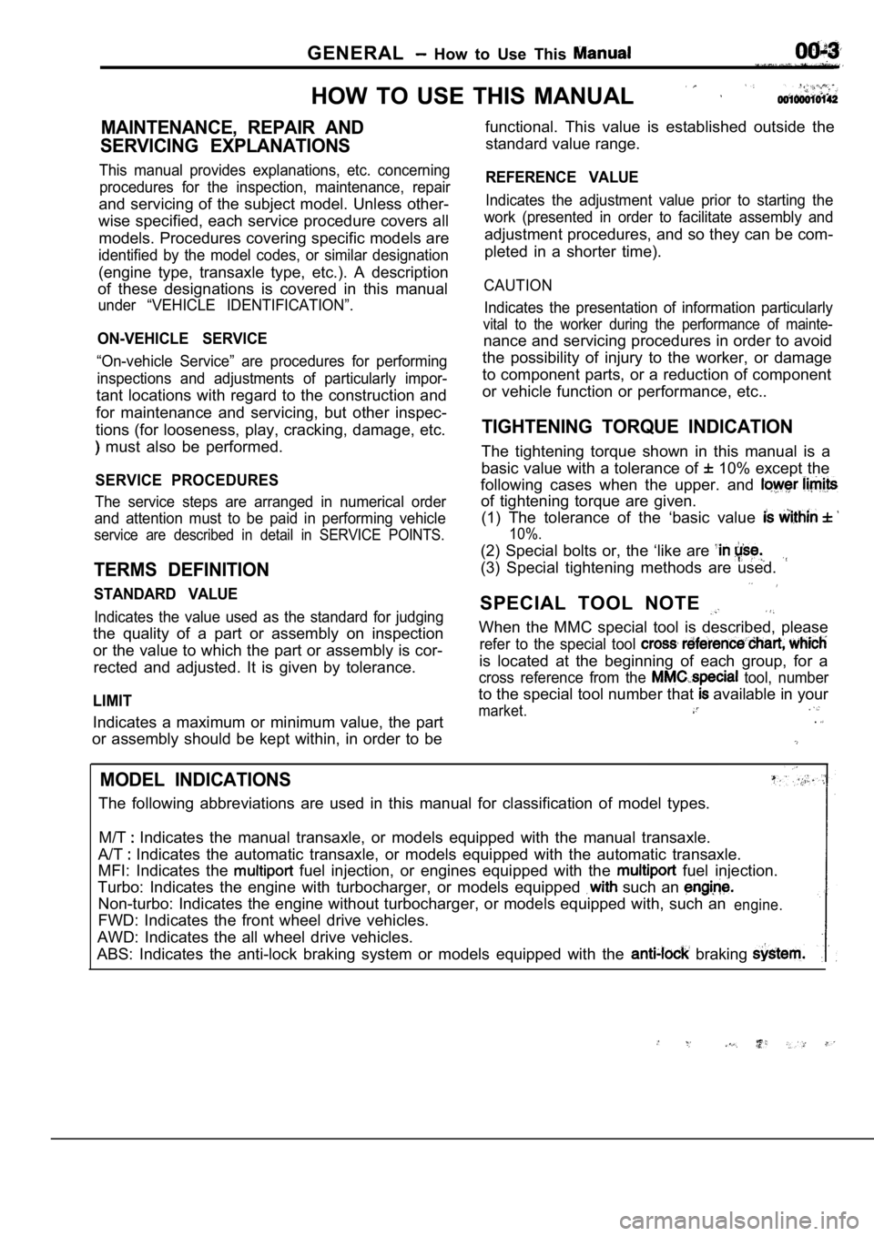
HOW TO USE THIS MANUAL
MAINTENANCE, REPAIR AND
SERVICING EXPLANATIONS
This manual provides explanations, etc. concerning procedures for the inspection, maintenance, repair
and servicing of the subject model. Unless other-
wise specified, each service procedure covers all
models. Procedures covering specific models are
identified by the model codes, or similar designati on
(engine type, transaxle type, etc.). A description
of these designations is covered in this manual
under “VEHICLE IDENTIFICATION”.
ON-VEHICLE SERVICE
“On-vehicle Service” are procedures for performing
inspections and adjustments of particularly impor-
tant locations with regard to the construction and
for maintenance and servicing, but other inspec-
tions (for looseness, play, cracking, damage, etc.
must also be performed.
SERVICE PROCEDURES
The service steps are arranged in numerical order
and attention must to be paid in performing vehicle
service are described in detail in SERVICE POINTS.
TERMS DEFINITION
STANDARD VALUE
Indicates the value used as the standard for judgin g
the quality of a part or assembly on inspection
or the value to which the part or assembly is cor-
rected and adjusted. It is given by tolerance.
LIMIT
Indicates a maximum or minimum value, the part
or assembly should be kept within, in order to be functional. This value is established outside the
standard value range.
REFERENCE VALUE
Indicates the adjustment value prior to starting th e
work (presented in order to facilitate assembly and
adjustment procedures, and so they can be com-
pleted in a shorter time).
CAUTION
Indicates the presentation of information particula rly
vital to the worker during the performance of maint e-
nance and servicing procedures in order to avoid
the possibility of injury to the worker, or damage
to component parts, or a reduction of component
or vehicle function or performance, etc..
TIGHTENING TORQUE INDICATION
The tightening torque shown in this manual is a
basic value with a tolerance of
10% except the
following cases when the upper. and
of tightening torque are given. (1) The tolerance of the ‘basic value
10%.
(2) Special bolts or, the ‘like are
(3) Special tightening methods are used.
SPECIAL TOOL NOTE
When the MMC special tool is described, please
refer to the special tool
is located at the beginning of each group, for a
cross reference from the tool, number
to the special tool number that available in your
market..
MODEL INDICATIONS
The following abbreviations are used in this manual for classification of model types.
M/T
Indicates the manual transaxle, or models equipped with the manual transaxle.
A/T
Indicates the automatic transaxle, or models equip ped with the automatic transaxle.
MFI: Indicates the
fuel injection, or engines equipped with the fuel injection.
Turbo: Indicates the engine with turbocharger, or m odels equipped
such an
Non-turbo: Indicates the engine without turbocharger, or models equipped with, such anengine.
FWD: Indicates the front wheel drive vehicles.
AWD: Indicates the all wheel drive vehicles.
ABS: Indicates the anti-lock braking system or mode ls equipped with the
braking
Page 16 of 2103
G E N E R A L Vehicle
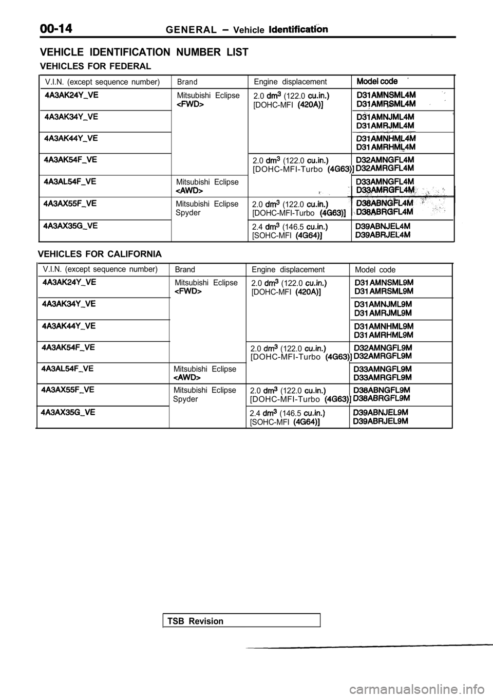
VEHICLE IDENTIFICATION NUMBER LIST
VEHICLES FOR FEDERAL
V.I.N. (except sequence number)BrandEngine displacement
Mitsubishi Eclipse2.0 (122.0
[DOHC-MFI
2.0 (122.0
[DOHC-MFI-Turbo
Mitsubishi Eclipse
Mitsubishi Eclipse2.0 (122.0 Spyder [DOHC-MFI-Turbo
2.4 (146.5
[SOHC-MFI
VEHICLES FOR CALIFORNIA
V.I.N. (except sequence number)Brand Engine displacement Model code
Mitsubishi Eclipse 2.0
(122.0
[DOHC-MFI
2.0 (122.0 [DOHC-MFI-Turbo
Mitsubishi Eclipse
Mitsubishi Eclipse 2.0 (122.0
Spyder[DOHC-MFI-Turbo
2.4 (146.5
[SOHC-MFI
TSB Revision
Page 17 of 2103
GENERAL Vehicle
Heat
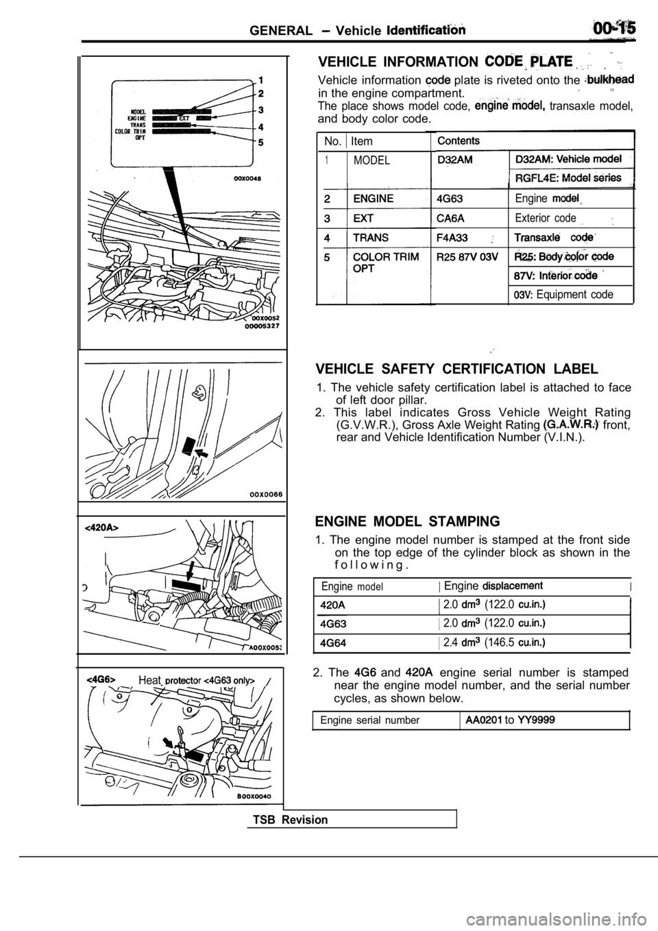
VEHICLE INFORMATION
Vehicle information plate is riveted onto the
in the engine compartment.
The place shows model code, transaxle model,
and body color code.
No. Item
1MODEL
Engine
Exterior code
Equipment code
VEHICLE SAFETY CERTIFICATION LABEL
1. The vehicle safety certification label is attached to face
of left door pillar.
2. This label indicates Gross Vehicle Weight Rating (G.V.W.R.), Gross Axle Weight Rating
front,
rear and Vehicle Identification Number (V.I.N.).
ENGINE MODEL STAMPING
1. The engine model number is stamped at the front side
on the top edge of the cylinder block as shown in t he
f o l l o w i n g .
Enginemodel Engine
2.0 (122.0
I
I 2.0 (122.0
2.4 (146.5
2. The and engine serial number is stamped
near the engine model number, and the serial number
cycles, as shown below.
Engine serial number to
TSB Revision
Page 18 of 2103
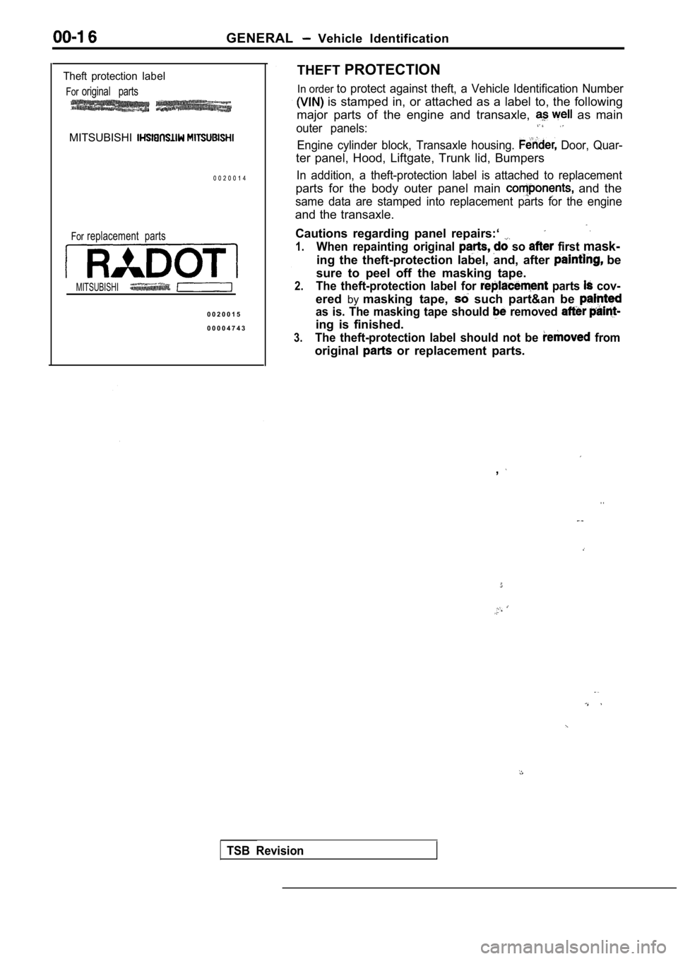
GENERAL Vehicle Identification
Theft protection label
Fororiginal parts
MITSUBISHI
0 0 2 0 0 1 4
Forreplacement parts
MITSUBISHI
0 0 2 0 0 1 5
0 0 0 0 4 7 4 3THEFT
PROTECTION
In order to protect against theft, a Vehicle Identification Number
is stamped in, or attached as a label to, the foll owing
major parts of the engine and transaxle,
as main
outer panels:
Engine cylinder block, Transaxle housing. Door, Quar-
ter panel, Hood, Liftgate, Trunk lid, Bumpers
In addition, a theft-protection label is attached t o replacement
parts for the body outer panel main and the
same data are stamped into replacement parts for th e engine
and the transaxle.
Cautions regarding panel repairs:‘
1.When repainting original so first mask-
ing the theft-protection label, and, after be
sure to peel off the masking tape.
2.The theft-protection label for parts cov-
ered bymasking tape, such part&an be
as is. The masking tape should removed
ing is finished.
3.The theft-protection label should not be from
original or replacement parts.
,
. .
TSB Revision
Page 19 of 2103
GENERAL Vehicle
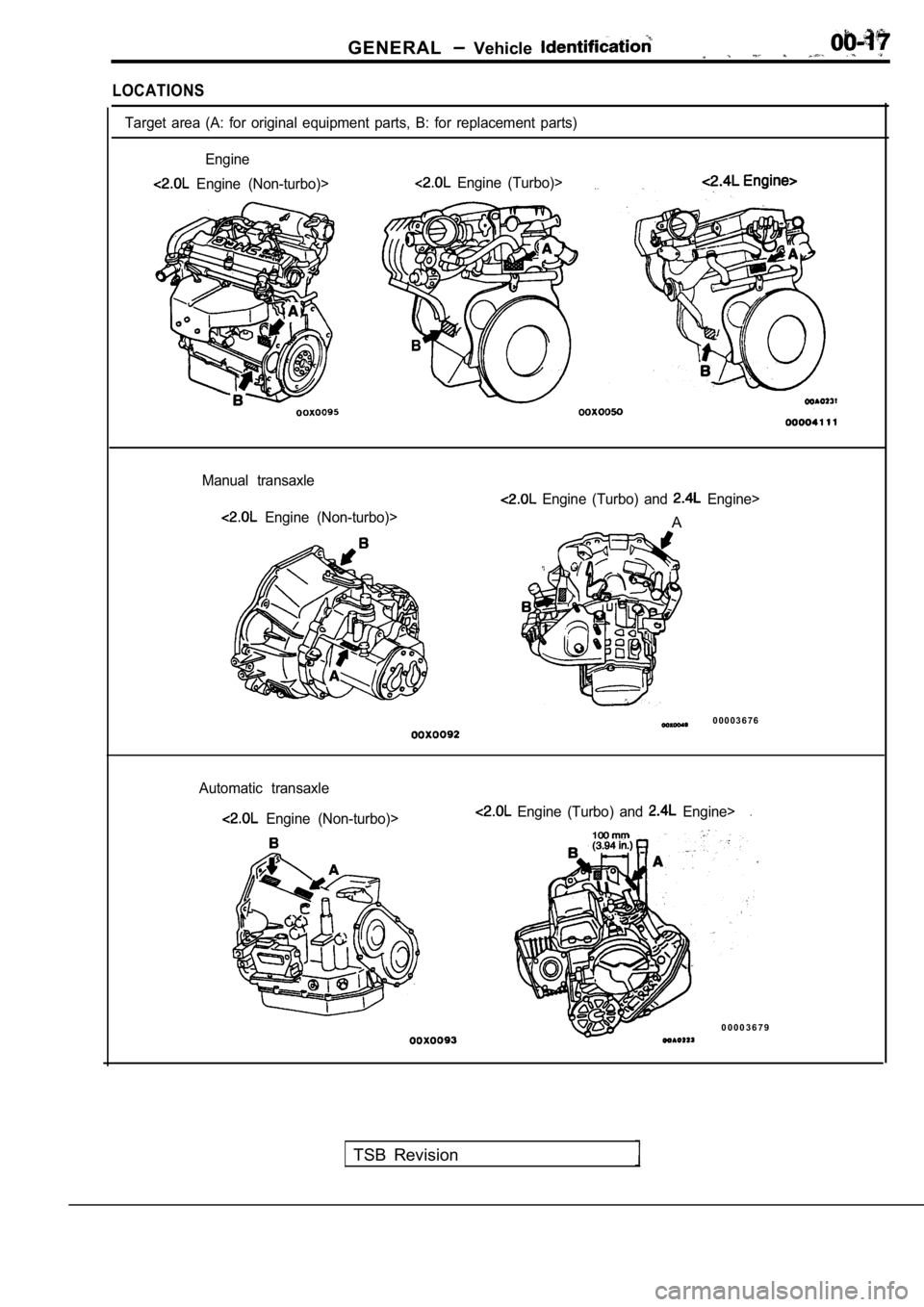
LOCATIONS
Target area (A: for original equipment parts, B: for replacement parts)
Engine
Engine (Non-turbo)> Engine (Turbo)>
Manual transaxle
Engine (Non-turbo)>
Engine (Turbo) and Engine>
A
0 0 0 0 3 6 7 6
Automatic transaxle
Engine (Non-turbo)> Engine (Turbo) and Engine>.
0 0 0 0 3 6 7 9
TSB Revision
Page 23 of 2103
GENERAL Precautions before Service . .
Caution
1.Before connecting or disconnecting the negative
be sure to turn off the ignition and
the lighting switch.
(if this is not done, the possibility semi-
conductor parts being damaged.)
2.After completion of the work steps [when the bat-
tery’s negative terminal is connected], warm
up the engine and allow it for approximately
five minutes under the conditions be-
low, in order to stabilize the engine condi-
tions, and then check to be sure that idling’ is
satisfactory.
Engine temperature:
Lights, electric fans, accessories: OFF
Transaxle: Neutral position
(A/T models: “N” or “P”)
Steering
neutral (center) position
mm (in.)
Scan tool
ROM pack
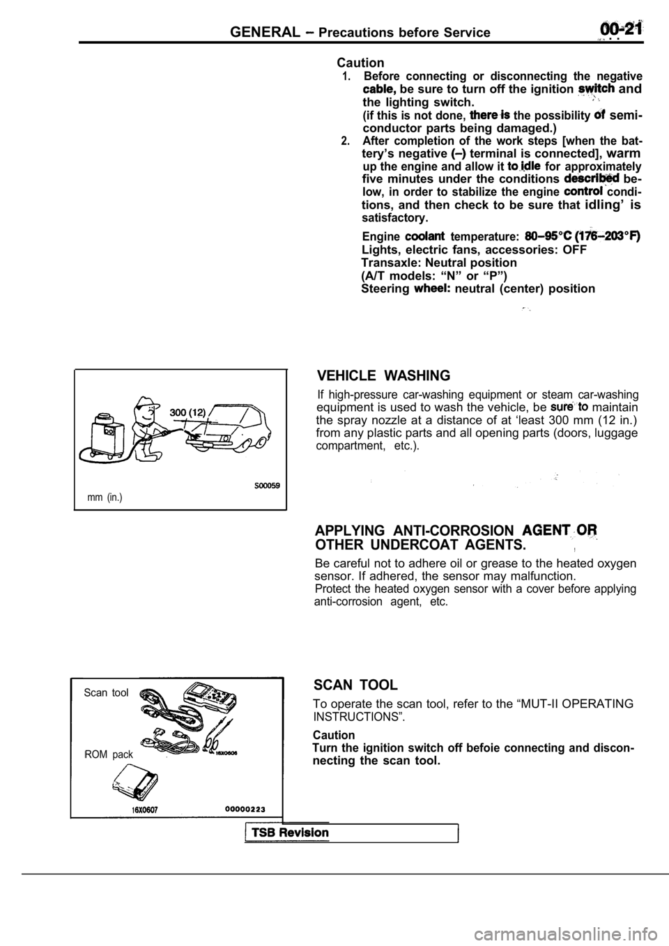
VEHICLE WASHING
If high-pressure car-washing equipment or steam car -washing
equipment is used to wash the vehicle, be maintain
the spray nozzle at a distance of at ‘least 300 mm (12 in.)
from any plastic parts and all opening parts (doors , luggage
compartment, etc.).
APPLYING ANTI-CORROSION
OTHER UNDERCOAT AGENTS.,
Be careful not to adhere oil or grease to the heate d oxygen
sensor. If adhered, the sensor may malfunction.
Protect the heated oxygen sensor with a cover befor e applying
anti-corrosion agent, etc.
SCAN TOOL
To operate the scan tool, refer to the “MUT-II OPER ATING
INSTRUCTIONS”.
Caution
Turn the ignition switch off befoie connecting and discon-
necting the scan tool.
Page 29 of 2103
GENERAL Special Handling Instructions for Models
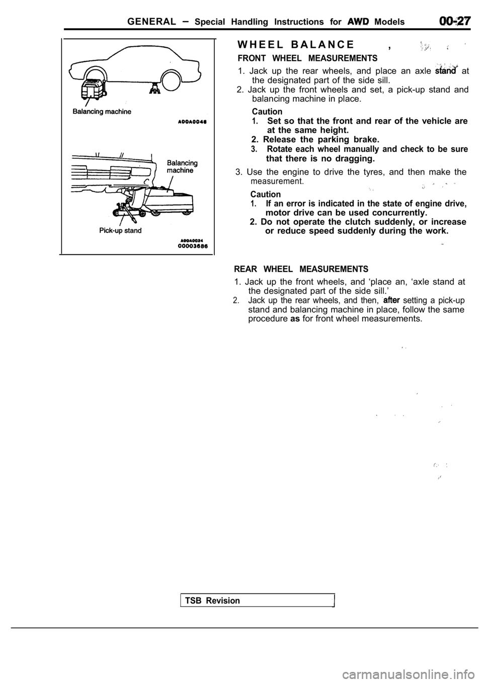
W H E E L B A L A N C E,
FRONT WHEEL MEASUREMENTS
1. Jack up the rear wheels, and place an axle at
the designated part of the side sill.
2. Jack up the front wheels and set, a pick-up stan d and
balancing machine in place.
Caution
1.Set so that the front and rear of the vehicle are
at the same height.
2. Release the parking brake.
3.Rotate each wheel manually and check to be sure
that there is no dragging.
3. Use the engine to drive the tyres, and then make the
measurement.
Caution
1.If an error is indicated in the state of engine drive,
motor drive can be used concurrently.
2. Do not operate the clutch suddenly, or increase or reduce speed suddenly during the work.
REAR WHEEL MEASUREMENTS
1. Jack up the front wheels, and ‘place an, ‘axle s tand at
the designated part of the side sill.’
2.Jack up the rear wheels, and then, setting a pick-up
stand and balancing machine in place, follow the sa me
procedure asfor front wheel measurements.
TSB Revision
Page 32 of 2103
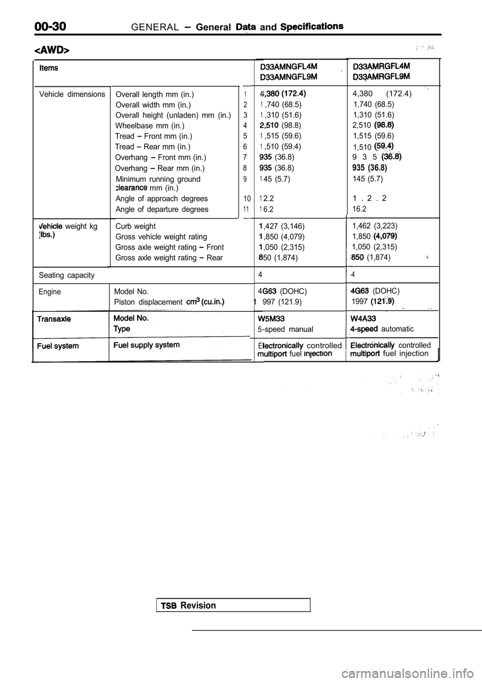
GENERAL General and
Vehicle dimensions
weight kg
Overall length mm (in.)
Overall width mm (in.)
Overall height (unladen) mm (in.)
Wheelbase mm (in.)
Tread
Front mm (in.)
Tread
Rear mm (in.)
Overhang
Front mm (in.)
Overhang
Rear mm (in.)
Minimum running ground
mm (in.)
Angle of approach degrees
Angle of departure degrees
Curb weight
Gross vehicle weight rating
Gross axle weight rating
Front
Gross axle weight rating
Rear
1
2
3
4 5
6
7
8
9
10
11
Seating capacity
EngineModel No.
Piston displacement
4
1,740 (68.5)
1,310 (51.6)
(98.8)
1,515 (59.6)
1,510 (59.4)
(36.8)
(36.8)
145 (5.7)
4,380 (172.4)
1,740 (68.5)
1,310 (51.6)
2,510
1,515 (59.6)
1,510
9 3 5
935 (36.8)
145 (5.7)
12.2
16.2
,427 (3,146)
,850 (4,079)
,050 (2,315)
50 (1,874)
4
4
1
5
El
1 . 2 . 2
16.2
1,462 (3,223)
1,850
1,050 (2,315)
(1,874)
4
(DOHC)
997 (121.9)
-speed manual
(DOHC)
1997
automatic
controlled controlled
fuel fuel injection
Revision
Page 35 of 2103
GENERAL Lubrication arid Maintenance,
00100120067
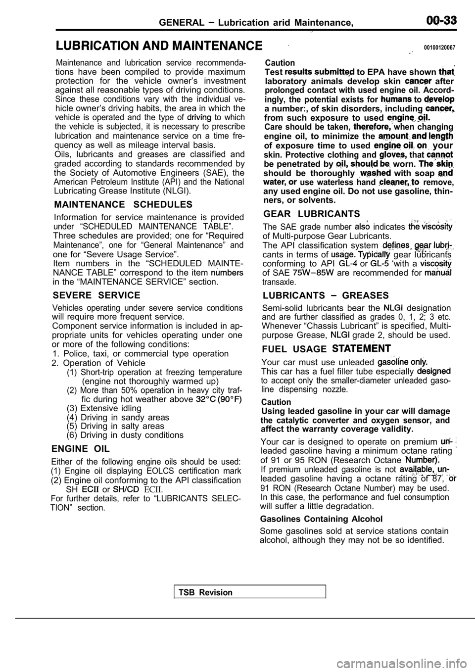
Maintenance and lubrication service recommenda-
tions have been compiled to provide maximum
protection for the vehicle owner’s investment
against all reasonable types of driving conditions.
Since these conditions vary with the individual ve-
hicle owner’s driving habits, the area in which the
vehicle is operated and the type of to which
the vehicle is subjected, it is necessary to prescr ibe
lubrication and maintenance service on a time fre-
quency as well as mileage interval basis.
Oils, lubricants and greases are classified and
graded according to standards recommended by
the Society of Automotive Engineers (SAE), the
American Petroleum Institute (API) and the National
Lubricating Grease Institute (NLGI).
MAINTENANCE SCHEDULES
Information for service maintenance is provided
under “SCHEDULED MAINTENANCE TABLE”.
Three schedules are provided; one for “Required
Maintenance”, one for “General Maintenance” and
one for “Severe Usage Service”. Item numbers in the “SCHEDULED MAINTE-
NANCE TABLE” correspond to the item
in the “MAINTENANCE SERVICE” section.
SEVERE SERVICE
Vehicles operating under severe service conditions
will require more frequent service. Component service information is included in ap-
propriate units for vehicles operating under one
or more of the following conditions:
1. Police, taxi, or commercial type operation
2. Operation of Vehicle
(1) Short-trip operation at freezing temperature
(engine not thoroughly warmed up)
(2) More than 50% operation in heavy city traf-
fic during hot weather above
(3) Extensive idling
(4) Driving in sandy areas
(5) Driving in salty areas
(6) Driving in dusty conditions
ENGINE OIL
Either of the following engine oils should be used:
(1) Engine oil displaying EOLCS certification mark
(2) Engine oil conforming to the API classification SH
or ECII.
For further details, refer to “LUBRICANTS SELEC-
TION” section.
Caution
Test to EPA have shown
laboratory animals develop skin after
prolonged contact with used engine oil. Accord-
ingly, the potential exists for
to
a number:, of skin disorders, including
from such exposure to used
Care should be taken, when changing
engine oil, to minimize the
of exposure time to used your
skin. Protective clothing and that
be penetrated by worn.
should be thoroughly with soap
use waterless hand remove,
any used engine oil. Do not use gasoline, thin- ners, or solvents.
GEAR LUBRICANTS
The SAE grade number indicates
of Multi-purpose Gear Lubricants.
The API classification system
cants in terms of gear lubricants
conforming to API
or ‘with a
of SAE are recommended for
transaxle.
LUBRICANTS GREASES
Semi-solid lubricants bear the
designation
and are further classified as grades 0, 1, 2; 3 etc .
Whenever “Chassis Lubricant” is specified, Multi-
purpose Grease,
grade 2, should be used.
FUEL USAGE
Your car must use unleaded
This car has a fuel filler tube especially
to accept only the smaller-diameter unleaded gaso- line dispensing nozzle.
Caution
Using leaded gasoline in your car will damage
the catalytic converter and oxygen sensor, and
affect the warranty coverage validity.
Your car is designed to operate on premium
leaded gasoline having a minimum octane rating
of 91 or 95 RON (Research Octane
If premium unleaded gasoline is not
leaded gasoline having a octane rating of 87,
91 RON (Research Octane Number) may be used. In this case, the performance and fuel consumption
will suffer a little degradation.
Gasolines Containing Alcohol
Some gasolines sold at service stations contain
alcohol, although they may not be so identified.
TSB Revision