ignition MITSUBISHI SPYDER 1990 Service Repair Manual
[x] Cancel search | Manufacturer: MITSUBISHI, Model Year: 1990, Model line: SPYDER, Model: MITSUBISHI SPYDER 1990Pages: 2103, PDF Size: 68.98 MB
Page 3 of 2103
CONTENTS
GENERAL DATA AND SPECIFICATIONS. .
HOW TO USE THIS MANUAL. . . . . . . . . . . . .3
Explanation of Manual Contents. . . . . . . . . . . . . .4
Model Indications
. . . . . . . . . . . . . . . . . . . . . . . . . . .3
Maintenance, Repair and
Servicing Explanations. . . . . . . . . . . . . . . . . . . . . . .
3
Special Tool Note. . . . . . . . . . . . . . . . . . . . . . . . . . .3
Terms Definition. . . . . . . . . . . . . . . . . . . . . . . . . . . .3
Tightening Torque Indication. . . . . . . . . . . . . . . . .3
HOW TO USE TROUBLESHOOTING/
INSPECTION SERVICE POINTS. . . . . . . . . . . .6
Connector Inspection Service Points
. . . . . . . . . .10
Connector Measurement Service Points . . . . . . . .9
How to Cope with Intermittent Malfunctions . . .11
How to Use the Inspection Procedures
. . . . . . .
8
Inspection Service Points for a Blown Fuse . . .
12
Troubleshooting Contents. . . . . . . . . . . . . . . . . . . .6
LUBRICATION AND MAINTENANCE . . . . . . .33
MAIN SEALANT AND ADHESIVE TABLE
. .
MAINTENANCE SERVICE. . . . . . . . . . . . . . . . . .38
Air Cleaner Element. . . . . . . . . . . . . . . . . . . . . . . .39
Automatic Transaxle Fluid
. . . . . . . . . . . . . . . . . . .45
Ball Joint and Steering Linkage Seals
. . . . . . . .50
Brake Hoses.... . . . . . . . . . . . . . . . . . . . . . . . . . . .50
Disc Brake Pads. . . . . . . . . . . . . . . . . . . . . . . . . . . .49
Drive Belt (For Generator, Water Pump, Power
Steering Pump). . . . . . . . . . . . . . . . . . . . . . . . . . . . .40
Drive Shaft Boots
. . . . . . . . . . . . . . . . . . . . . . . . . . .50
Engine Coolant. . . . . . . . . . . . . . . . . . . . . . . . . . . . .48
Engine Oil. . . . . . . . . . . . . . . . . . . . . . . . . . . . . . . . . .42
Engine Oil Filter. . . . . . . . . . . . . . . . . . . . . . . . . . . .43
Evaporative Emission Control System . . . . . . . . .
Exhaust System. . . . . . . . . . . . . . . . . . . . . . . . . . . . .54
Fuel Hoses. . . . . . . . . . . . . . . . . . . . . . . . . . . . . . . . .38
Fuel System. . . . . . . . . . . . . . . . . . . . . . . . . . . . . . . .38
Ignition Cables. . . . . . . . . . . . . . . . . . . . . . . . . . . . . .
40
Manual Transaxle Oil . . . . . . . . . . . . . . . . . . . . . . . .
Rear Axle Oil. . . . . . . . . . . . . . . . . . . . . . . . . . . .
50
Rear Drum Brake Linings and
Rear Wheel Cylinders . . . . . . . . . . . . . . . . . . . . . . .
Spark Plugs. . . . . . . . . . . . . . . . . . . . . . . . . . . . . . . .40
SRS System . . . . . . . . . . . . . . . . . . . . . . . . . . . . . . .51
Timing Belt. . . . . . . . . . . . . . . . . . . . . . . . . . . . . . . . .40
Transfer Oil. . . . . . . . . . . . . . . . . . . . . . . . . . . . . . . .48
PRECAUTIONS BEFORE SERVICE. . . . . . . .20
RECOMMENDED LUBRICANTS
LUBRICANT CAPACITIES TABLE. . . . . . . . . .34
SCHEDULED MAINTENANCE TABLE. . . . .
SPECIAL HANDLING INSTRUCTIONS FOR
AWD MODELS . . . . . . . . . . . . . . . . . . . . . . . . . . . .
26
TIGHTENING TORQUE. . . . . . . . . . . . . . . . . . . .32
TOWING AND HOISTING . . . . . . . . . . . . . . . . . .22
VEHICLE IDENTIFICATION. . . . . . . . . . . . . . . . .13
Engine Model Stamping. . . . . . . . . . . . . . . . . . . . .15
Theft Protection. . . . . . . . . . . . . . . . . . . . . . . . . . . . .18
Vehicle Identification Code Chart Plate
. . . . . . .13
Vehicle Identification Number List. . . . . . . . . . . .14
Vehicle Identification Number Location. . . . . . . .13
Vehicle Information Code Plate.. . . . . . . . . . . . . .15
Vehicle Safety Certification Label
. . . . . . . . . . . . .15
Page 9 of 2103
GENERAL How to Use Troubleshooting/Inspection Service Points
4.After repair or replacement, recheck the voltmeter to confirm the repair
the problem.
Terminal Resistance and Continuity Checks
1. Turn the ignition switch to off.
2. Disconnect the ECU connector.
3.Measure the resistance and check for continuity bet ween the terminals of the ECU
connector while referring to the check chart.
NOTE
Checks don’t have to be carried out in the order gi ven in the chart.
Cautlon
If resistance and continuity checks are performed the wrong terminals, damage
vehicle wiring, sensors, ECU, and/or ohmmeter may o ccur.
Use care to prevent this!
4.If the ohmmeter shows any deviation from the Normal Condition value, check the corresponding
5.
sensor, actuator and related electrical wiring, then repair or replace.
After repair or replacement, recheck with the ohmme ter to confirm that the repair
the problem.
10. INSPECTION PROCEDURES USING AN OSCILLOSCOPE
When there are inspection procedures using an oscil loscope, these are listed here.
,
TSB Revision
Page 11 of 2103
GENERAL How to Use Troubleshooting/Inspection Service ‘Points
CONNECTOR
Turn the ignition switch to when connecting and discon-
necting the connectors, and turn the ignition switch to ON
when measuring if there are no instructions to the contrary.
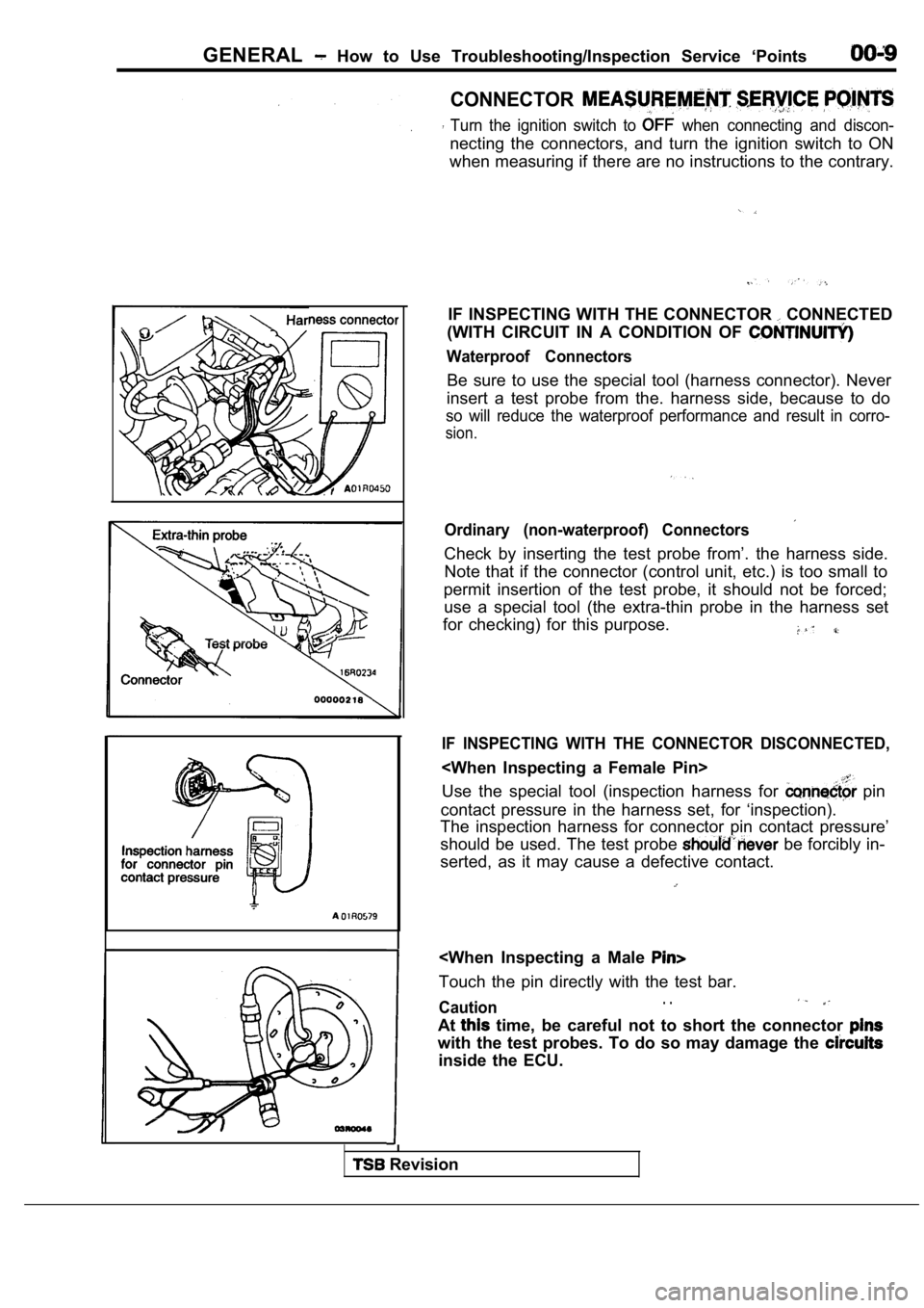
IF INSPECTING WITH THE CONNECTOR
CONNECTED
(WITH CIRCUIT IN A CONDITION OF
Waterproof Connectors
Be sure to use the special tool (harness connector) . Never
insert a test probe from the. harness side, because to do
so will reduce the waterproof performance and result in corro-
sion.
Ordinary (non-waterproof) Connectors
Check by inserting the test probe from’. the harness side.
Note that if the connector (control unit, etc.) is too small to
permit insertion of the test probe, it should not b e forced;
use a special tool (the extra-thin probe in the har ness set
for checking) for this purpose.
IF INSPECTING WITH THE CONNECTOR DISCONNECTED,
Use the special tool (inspection harness for
pin
contact pressure in the harness set, for ‘inspectio n).
The inspection harness for connector pin contact pr essure’
should be used. The test probe
be forcibly in-
serted, as it may cause a defective contact.
Caution. .
At time, be careful not to short the connector
with the test probes. To do so may damage the
inside the ECU.
Revision
Page 23 of 2103
GENERAL Precautions before Service . .
Caution
1.Before connecting or disconnecting the negative
be sure to turn off the ignition and
the lighting switch.
(if this is not done, the possibility semi-
conductor parts being damaged.)
2.After completion of the work steps [when the bat-
tery’s negative terminal is connected], warm
up the engine and allow it for approximately
five minutes under the conditions be-
low, in order to stabilize the engine condi-
tions, and then check to be sure that idling’ is
satisfactory.
Engine temperature:
Lights, electric fans, accessories: OFF
Transaxle: Neutral position
(A/T models: “N” or “P”)
Steering
neutral (center) position
mm (in.)
Scan tool
ROM pack
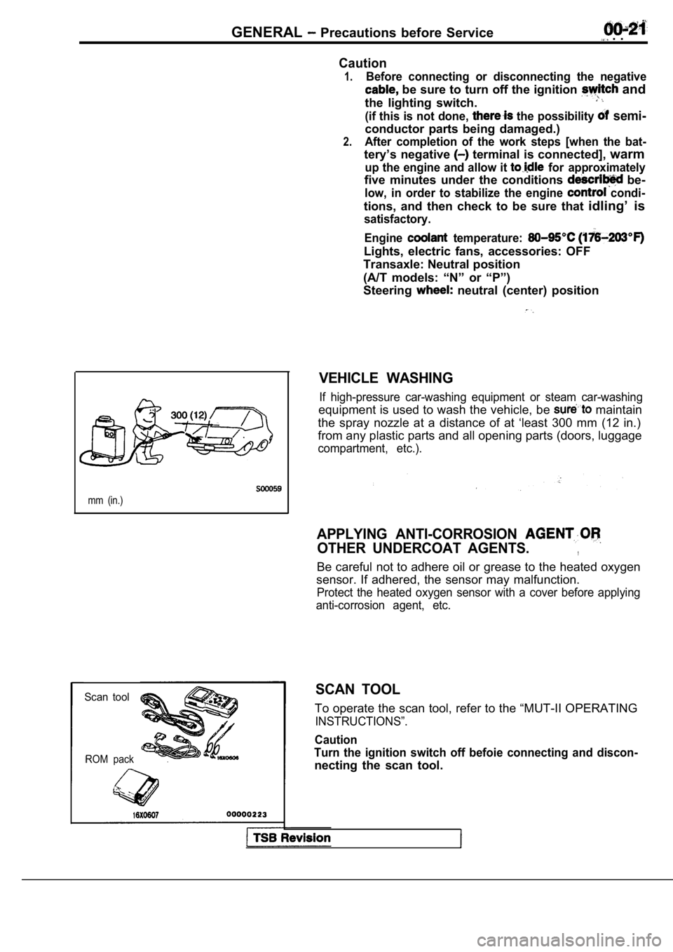
VEHICLE WASHING
If high-pressure car-washing equipment or steam car -washing
equipment is used to wash the vehicle, be maintain
the spray nozzle at a distance of at ‘least 300 mm (12 in.)
from any plastic parts and all opening parts (doors , luggage
compartment, etc.).
APPLYING ANTI-CORROSION
OTHER UNDERCOAT AGENTS.,
Be careful not to adhere oil or grease to the heate d oxygen
sensor. If adhered, the sensor may malfunction.
Protect the heated oxygen sensor with a cover befor e applying
anti-corrosion agent, etc.
SCAN TOOL
To operate the scan tool, refer to the “MUT-II OPER ATING
INSTRUCTIONS”.
Caution
Turn the ignition switch off befoie connecting and discon-
necting the scan tool.
Page 42 of 2103
GENERAL Maintenance
Incorrect Correct
5. SPARK PLUGS
1.Spark plugs must spark properly to assure proper engine
performance and reduce exhaust emission
Therefore, they should be periodically with new
ones.
2. The new plugs should be checked gap.
Spark plug gap:, . .
Engine (Turbo)>’
mm
Engine (Non-turbo)> ,
1.22-1.35 mm
in.)
Engine> .
in.)
3. Install the spark plug and tighten to the
Tightening torque:
Engine (Turbo) and Engine>
25 Nm (18
E n g i n e ( N o n - t u r b o ) >
28 Nm (20
6. IGNITION CABLES (Replace)
The ignition cables should. be replaced periodicall y with new
ones. After replacing, make sure that the ignition cables are
routed properly and fully seated.
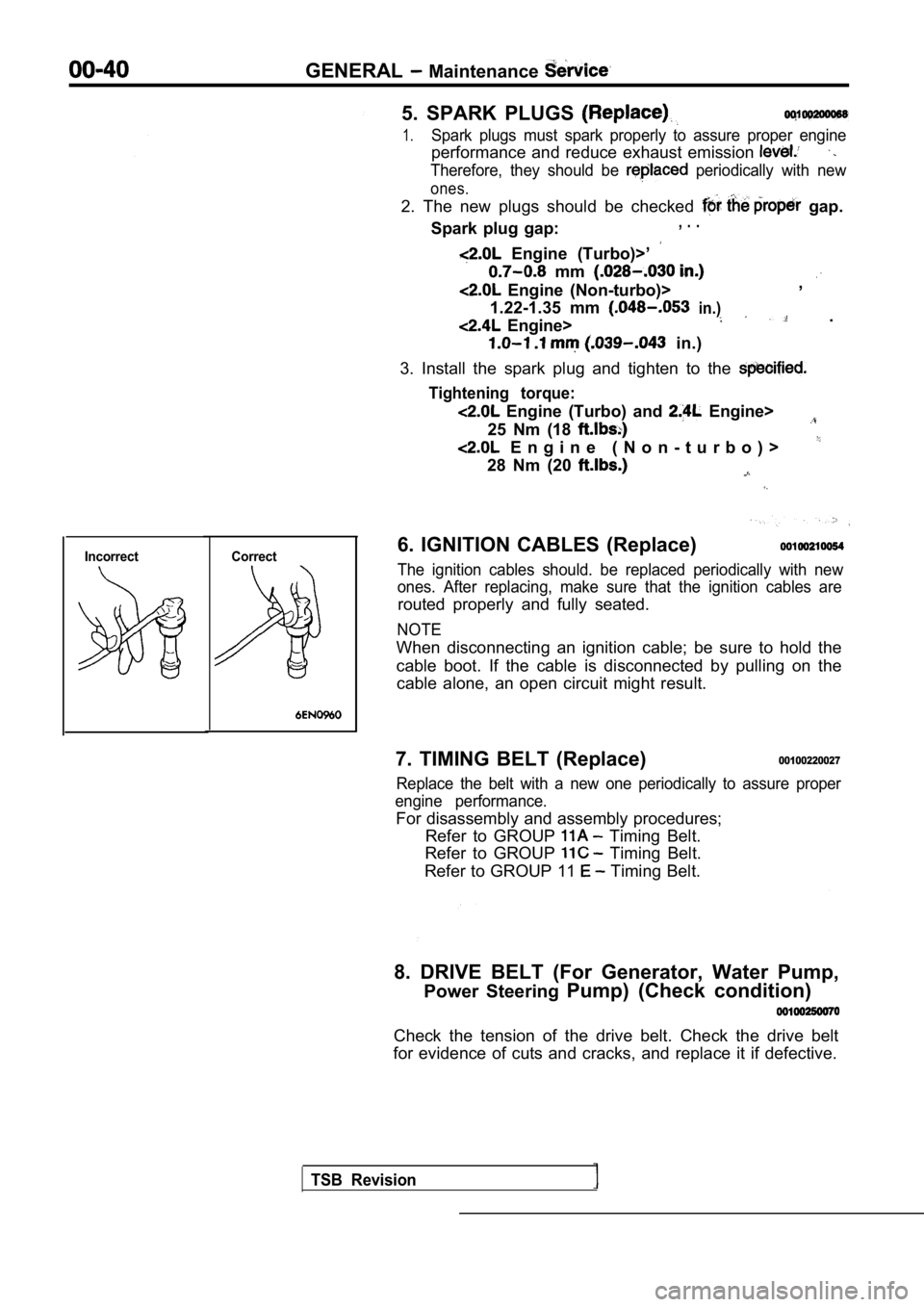
NOTE
When disconnecting an ignition cable; be sure to ho ld the
cable boot. If the cable is disconnected by pulling on the
cable alone, an open circuit might result.
7. TIMING BELT (Replace)
00100220027
Replace the belt with a new one periodically to ass ure proper
engine performance.
For disassembly and assembly procedures; Refer to GROUP
Timing Belt.
Refer to GROUP
Timing Belt.
Refer to GROUP 11
Timing Belt.
8. DRIVE BELT (For Generator, Water Pump, Power Steering Pump) (Check condition)
Check the tension of the drive belt. Check the driv e belt
for evidence of cuts and cracks, and replace it if defective.
TSB Revision
Page 53 of 2103
GENERAL Maintenance
21 SYSTEM component
damage, to wiring,
harness, etc.)
Certification labelManufacture dateI
SRSlight
Insulating tape
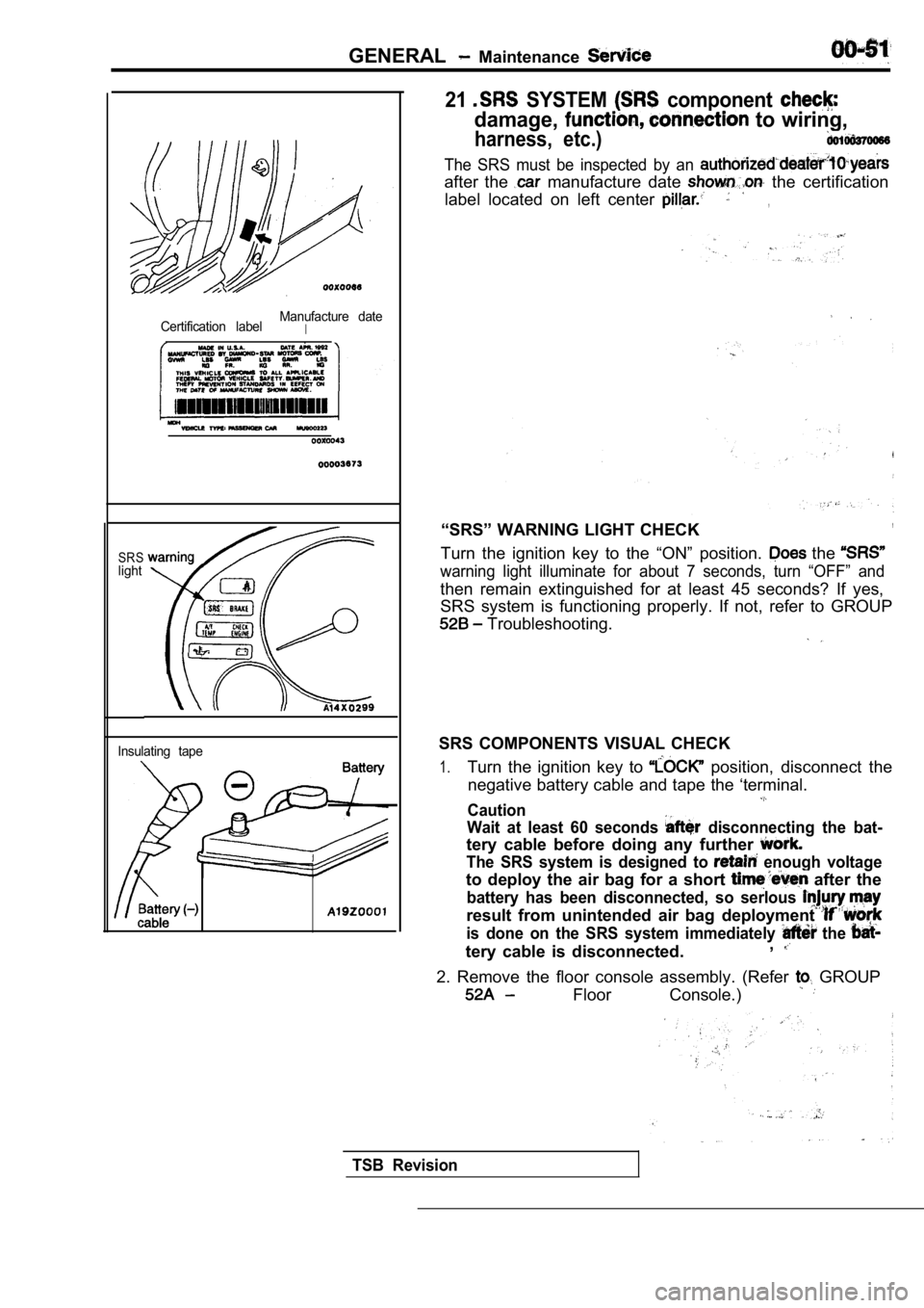
The SRS must be inspected by an
after the manufacture date the certification
label located on left center
,
“SRS” WARNING LIGHT CHECK,
Turn the ignition key to the “ON” position. the
warning light illuminate for about 7 seconds, turn “OFF” and
then remain extinguished for at least 45 seconds? I f yes,
SRS system is functioning properly. If not, refer t o GROUP
Troubleshooting.
SRS COMPONENTS VISUAL CHECK
1.Turn the ignition key to position, disconnect the
negative battery cable and tape the ‘terminal.
Caution
Wait at least 60 seconds
disconnecting the bat-
tery cable before doing any further
The SRS system is designed to enough voltage
to deploy the air bag for a short after the
battery has been disconnected, so serlous
result from unintended air bag deployment
is done on the SRS system immediately the
tery cable is disconnected. ,
2. Remove the floor console assembly. (Refer GROUP
Floor Console.)
TSB Revision
Page 61 of 2103
ENGINE
CONTENTS
CAMSHAFT AND CAMSHAFT OIL
SEAL. . . . . . . . . . . . . . . . . . . . . . . . . . . . . . . . . .22
CRANKSHAFT FRONT OIL SEAL . . . . . . . 28
CRANKSHAFT PULLEY . . . . . . . . . . . . . . . . . 21
CRANKSHAFT REAR OIL SEAL. . . . . . . .29
Curb Speed Check. . . . . . . . . . . . . . . . . .10
Drive Belt Tension Check and
Adjustment . , . . . . . . . . . . . . . . . . . . . . . . . . . . . 7
Mixture Check . . . . . . . . . . . . . . . . . .
. . . . .10
Ignition Timing Check. . . . . . . . . . . .. . . . . . . . .
Lash Adjuster Check . . . . . . . . . . . . . . . .
CYLINDER HEAD GASKET . . . . . . . . . . . . .31
ENGINE ASSEMBLY. . . . . . . . . . . . . . . . . . . .16
GENERAL INFORMATION. . . . . . . . . . . . . . . .2
OIL PAN AND OIL SCREEN . . . . . . . . . . . .26
ON-VEHICLE SERVICE. . . . . . . . . . . . . . . . .7
Basic Idle Speed Adjustment
. . . . . . . . . . . . . . . . . . . . . . Refer to GROUP
Lash Adjuster Replacement. . . . . . . .. . . .15
Manifold Vacuum Check. . . . . . . . . . . . . . . ....13
SEALANTS. . . . . . . . . . . . . . . . . . . . . . . . . . . . . .
SERVICE SPECIFICATIONS. . . . . . . . . . . . . .3
SPECIAL TOOLS. . . . . . . . . . . . . . . . . . . . . . . .4
BELT. . . . . . . . . . . . . . . . . . . . . . . . . . .36
TIMING BELT . . . . . . . . . . . . . . . . . . . . . . . .41
Compression Pressure Check . . . . . . . . . . . .
. . 11TROUBLESHOOTING . . . . . . . . . . . . . . . . . . . 6
Page 63 of 2103
ENGINE Service Specifications
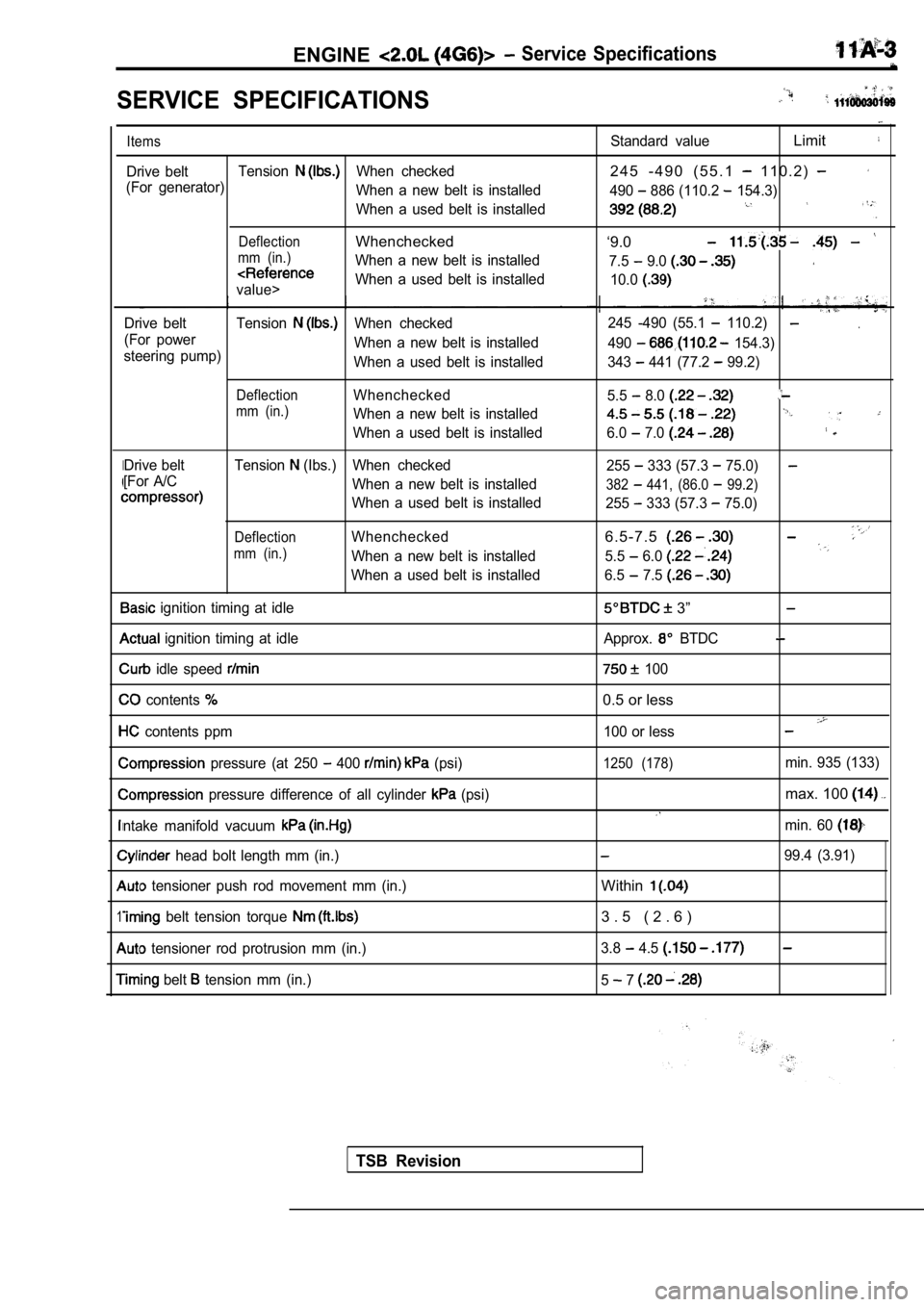
SERVICE SPECIFICATIONS
I
1
Items
Drive beltTensionWhen checked
(For generator) When a new belt is installed
When a used belt is installed
DeflectionWhenchecked
mm (in.)When a new belt is installed
value>When a used belt is installed
Drive belt Tension
When checked
(For power When a new belt is installed
steering pump) When a used belt is installed
DeflectionWhenchecked
mm (in.)When a new belt is installed
When a used belt is installed
Drive belt Tension
(Ibs.) When checked
[For A/C When a new belt is installed
When a used belt is installed
DeflectionWhenchecked
mm (in.)When a new belt is installed
When a used belt is installed
ignition timing at idle
ignition timing at idle
idle speed
contents
contents ppm
pressure (at 250 400 (psi)
pressure difference of all cylinder (psi)
ntake manifold vacuum
head bolt length mm (in.)
tensioner push rod movement mm (in.)
belt tension torque
tensioner rod protrusion mm (in.)
belt tension mm (in.)
Standard valueLimit
2 4 5 - 4 9 0 ( 5 5 . 1 1 1 0 . 2 )
490 886 (110.2 154.3)
‘9.0
7.5 9.0
10.0
.245 -490 (55.1 110.2)
490 154.3)
343
441 (77.2 99.2)
5.5
8.0
6.0 7.0
255 333 (57.3 75.0)
382 441, (86.0 99.2)
255 333 (57.3 75.0)
6 . 5 - 7 . 5
5.5 6.0
6.5 7.5
3”
Approx. BTDC
100
0.5 or less
100 or less
1250 (178)min. 935 (133)
max. 100
min. 60
99.4 (3.91)
Within
3 . 5 ( 2 . 6 )
3.8 4.5
5 7
TSB Revision
Page 69 of 2103
ENGINE On-vehicle
A/C COMPRESSOR DRIVE BELT TENSION ADJUSTMENT
1. Loosen tension pulley fixing bolt A.
2. Adjust belt tension with adjusting bolt B.
Standard value:
Items
Tension
(Ibs.)
Deflection
When a new belt isWhen a used belt is
installedinstalled
382-411255-333
6.5-7.5
3. Tighten fixing nut A.
Tightening torque: 23-26 Nm
4.Check the belt deflection and readjust if neces-
sary.
Caution
This check should be carried out after turning the
crankshaft one full rotation or more in the forward
direction (to the right).
IGNITION TIMING CHECK
1.Before inspection and adjustment set vehicle in the follow-
ing condition.
lEngine coolant temperature:
lLights, electric cooling fan and all accessories: OFF
lTransaxle: Neutral (P range on vehicles with
2. Turn the ignition switch to OFF and connect the scan
tool to the data link connector.
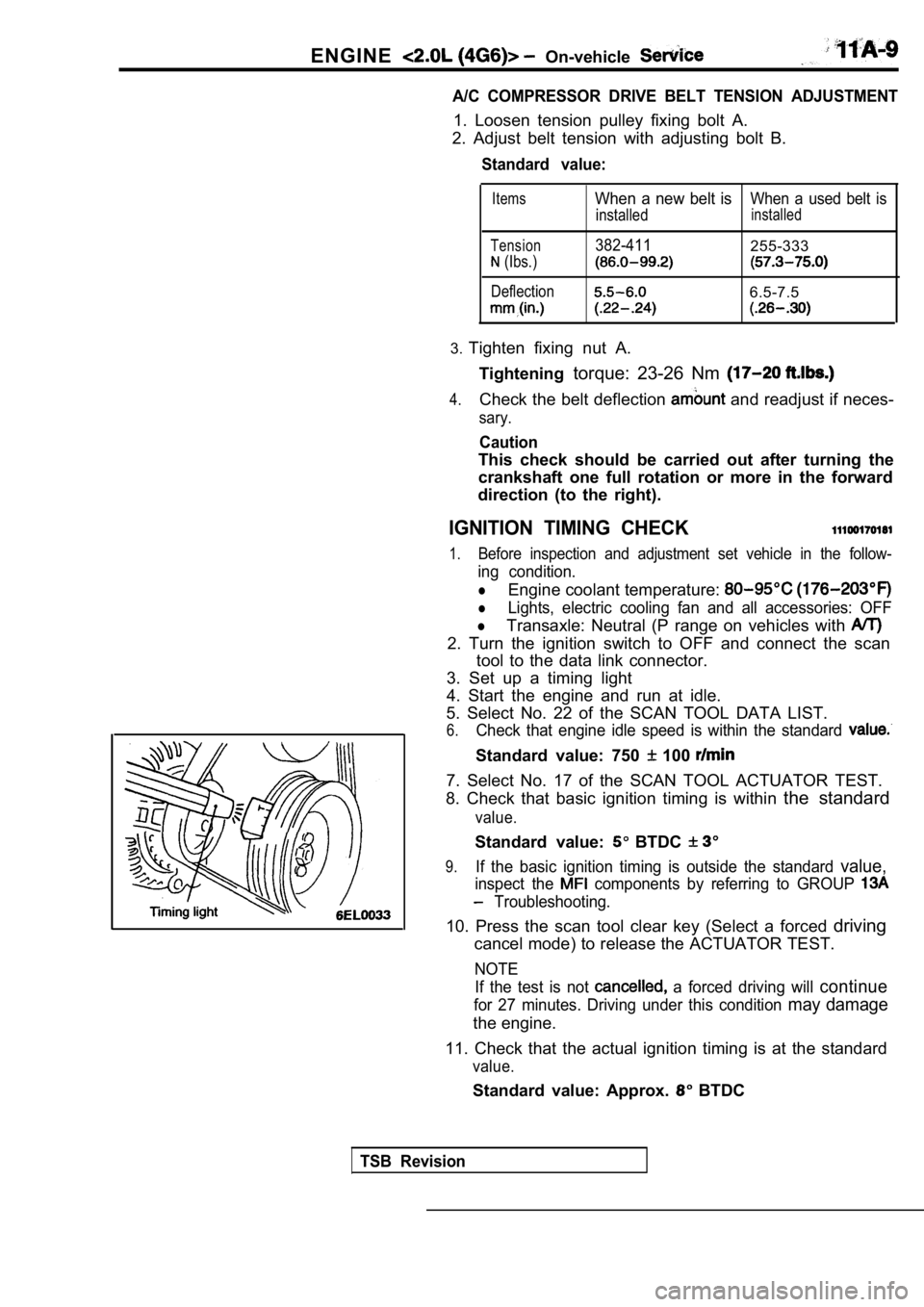
3. Set up a timing light
4. Start the engine and run at idle.
5. Select No. 22 of the SCAN TOOL DATA LIST.
6.Check that engine idle speed is within the standard
Standard value: 750 100
7. Select No. 17 of the SCAN TOOL ACTUATOR TEST.
8. Check that basic ignition timing is within the standard
value.
Standard value: BTDC
9.If the basic ignition timing is outside the standar d value,
inspect the components by referring to GROUP
Troubleshooting.
10. Press the scan tool clear key (Select a forced driving
cancel mode) to release the ACTUATOR TEST.
NOTE
If the test is not
a forced driving will continue
for 27 minutes. Driving under this condition may damage
the engine.
11. Check that the actual ignition timing is at the standard
value.
Standard value: Approx. BTDC
TSB Revision
Page 70 of 2103
ENGINE On-vehicle Service
NOTE
1.Ignition timing is variable within about even under
operating.
2. And it is automatically further advanced by abou t
from BTDC at higher altitudes.
CURB IDLE SPEED CHECK
1. Before inspection and adjustment, set vehicles in the
following condition.
lEngine coolant temperature:
lLights, electric cooling fan and all accessories: OFF
lTransaxle: Neutral (P range on vehicles with
2. Turn the ignition switch to OFF and connect the scan
tool to the data link connector.
3. Select No. 17 of the SCAN TOOL ACTUATOR TEST.
4. Check the basic ignition timing.
Standard
BTDC
5. Run the engine at idle for 2 minutes.
6. Select No. 22 of the SCAN TOOL DATA LIST.
7. Check the curb idle speed.
Standard value: 750
100
NOTE
The idle speed is controlled automatically by the i dle air
control system.
8. If the idle speed is outside the standard value, inspect
the components by referring to GROUP Trou-
bleshooting.
IDLE MIXTURE CHECK .
1.Before inspection, set in following
lEngine coolant temperature:
lLights, electric cooling fan all
lTransaxle: Neutral (P range on
2. Turn the ignition switch to OFF and, connect the scan
tool to the data link ,
3. Select No. 17 of the SCAN TOOL
4.Check that the basic ignition
value.
Standard value: BTDC
5. Run the engine 2,500 for 2 minutes.
6. Set the CO, HC tester.
7. Check the CO contents and the HC contents, at id le.
Standard value: CO contents: 0.5% or less
HC contents: 100 rpm or less
Revision