lock MITSUBISHI SPYDER 1990 Service Repair Manual
[x] Cancel search | Manufacturer: MITSUBISHI, Model Year: 1990, Model line: SPYDER, Model: MITSUBISHI SPYDER 1990Pages: 2103, PDF Size: 68.98 MB
Page 5 of 2103
GENERAL How to Use This
HOW TO USE THIS MANUAL
MAINTENANCE, REPAIR AND
SERVICING EXPLANATIONS
This manual provides explanations, etc. concerning procedures for the inspection, maintenance, repair
and servicing of the subject model. Unless other-
wise specified, each service procedure covers all
models. Procedures covering specific models are
identified by the model codes, or similar designati on
(engine type, transaxle type, etc.). A description
of these designations is covered in this manual
under “VEHICLE IDENTIFICATION”.
ON-VEHICLE SERVICE
“On-vehicle Service” are procedures for performing
inspections and adjustments of particularly impor-
tant locations with regard to the construction and
for maintenance and servicing, but other inspec-
tions (for looseness, play, cracking, damage, etc.
must also be performed.
SERVICE PROCEDURES
The service steps are arranged in numerical order
and attention must to be paid in performing vehicle
service are described in detail in SERVICE POINTS.
TERMS DEFINITION
STANDARD VALUE
Indicates the value used as the standard for judgin g
the quality of a part or assembly on inspection
or the value to which the part or assembly is cor-
rected and adjusted. It is given by tolerance.
LIMIT
Indicates a maximum or minimum value, the part
or assembly should be kept within, in order to be functional. This value is established outside the
standard value range.
REFERENCE VALUE
Indicates the adjustment value prior to starting th e
work (presented in order to facilitate assembly and
adjustment procedures, and so they can be com-
pleted in a shorter time).
CAUTION
Indicates the presentation of information particula rly
vital to the worker during the performance of maint e-
nance and servicing procedures in order to avoid
the possibility of injury to the worker, or damage
to component parts, or a reduction of component
or vehicle function or performance, etc..
TIGHTENING TORQUE INDICATION
The tightening torque shown in this manual is a
basic value with a tolerance of
10% except the
following cases when the upper. and
of tightening torque are given. (1) The tolerance of the ‘basic value
10%.
(2) Special bolts or, the ‘like are
(3) Special tightening methods are used.
SPECIAL TOOL NOTE
When the MMC special tool is described, please
refer to the special tool
is located at the beginning of each group, for a
cross reference from the tool, number
to the special tool number that available in your
market..
MODEL INDICATIONS
The following abbreviations are used in this manual for classification of model types.
M/T
Indicates the manual transaxle, or models equipped with the manual transaxle.
A/T
Indicates the automatic transaxle, or models equip ped with the automatic transaxle.
MFI: Indicates the
fuel injection, or engines equipped with the fuel injection.
Turbo: Indicates the engine with turbocharger, or m odels equipped
such an
Non-turbo: Indicates the engine without turbocharger, or models equipped with, such anengine.
FWD: Indicates the front wheel drive vehicles.
AWD: Indicates the all wheel drive vehicles.
ABS: Indicates the anti-lock braking system or mode ls equipped with the
braking
Page 17 of 2103
GENERAL Vehicle
Heat
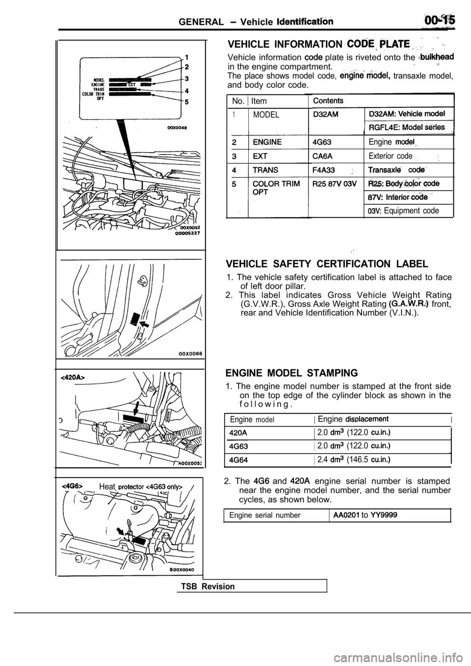
VEHICLE INFORMATION
Vehicle information plate is riveted onto the
in the engine compartment.
The place shows model code, transaxle model,
and body color code.
No. Item
1MODEL
Engine
Exterior code
Equipment code
VEHICLE SAFETY CERTIFICATION LABEL
1. The vehicle safety certification label is attached to face
of left door pillar.
2. This label indicates Gross Vehicle Weight Rating (G.V.W.R.), Gross Axle Weight Rating
front,
rear and Vehicle Identification Number (V.I.N.).
ENGINE MODEL STAMPING
1. The engine model number is stamped at the front side
on the top edge of the cylinder block as shown in t he
f o l l o w i n g .
Enginemodel Engine
2.0 (122.0
I
I 2.0 (122.0
2.4 (146.5
2. The and engine serial number is stamped
near the engine model number, and the serial number
cycles, as shown below.
Engine serial number to
TSB Revision
Page 18 of 2103
GENERAL Vehicle Identification
Theft protection label
Fororiginal parts
MITSUBISHI
0 0 2 0 0 1 4
Forreplacement parts
MITSUBISHI
0 0 2 0 0 1 5
0 0 0 0 4 7 4 3THEFT
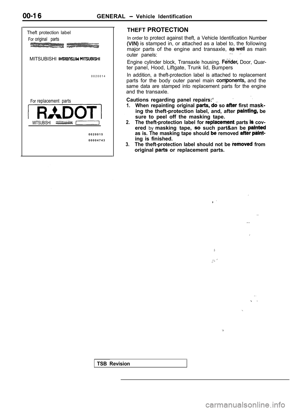
PROTECTION
In order to protect against theft, a Vehicle Identification Number
is stamped in, or attached as a label to, the foll owing
major parts of the engine and transaxle,
as main
outer panels:
Engine cylinder block, Transaxle housing. Door, Quar-
ter panel, Hood, Liftgate, Trunk lid, Bumpers
In addition, a theft-protection label is attached t o replacement
parts for the body outer panel main and the
same data are stamped into replacement parts for th e engine
and the transaxle.
Cautions regarding panel repairs:‘
1.When repainting original so first mask-
ing the theft-protection label, and, after be
sure to peel off the masking tape.
2.The theft-protection label for parts cov-
ered bymasking tape, such part&an be
as is. The masking tape should removed
ing is finished.
3.The theft-protection label should not be from
original or replacement parts.
,
. .
TSB Revision
Page 22 of 2103
GENERAL before Service
PRECAUTIONS BEFORE SERVICE.
SUPPLEMENTAL RESTRAINT SYSTEM
1. to follow when servicing SRS
(1) Be sure to read GROUP Supplemental Restraint System
For safe operations, please follow the directions a nd heed all
(2) Always use the designated special tools and tes t equipment.
(3) Wait at least 60 seconds after disconnecting the battery cable before” further work;
The SRS system is designed to retain enough voltage to deploy the air bag even after the battery
has been disconnected. Serious injury may result from unintended air bag deployment if work
is done on the SRS system immediately after the bat tery cable is disconnected.
(4) Never attempt to disassemble or repair the SRS components (SRS-ECU air bag module and
clock spring). If faulty, replace it.
(5) Warning labels must be heeded when servicing or handling SRS components. Warning labels
are located in the following locations.
Sun visor
l Glove box
. S R S - E C U
l Steering wheel
l Air bag module
l Clock spring
l Steering gear and linkage clamp
(6) Store components removed from the SRS
a clean and dry place.
The air bag module should be stored on a flat surfa ce and placed so that the pad surface is’
facing upward.
Do not place anything on top of it.
(7) Be sure to deploy the air bag before disposing of the air bag’module or disposing of a vehicle
equipped with an air bag. (Refer to GROUP
Air Bag Module Disposal Procedures.)
(8) Whenever you finish servicing the
check the SRS warning light operation to make sure
that the system functions properly.
2.Observe the following when carrying out operations on places where SRS components are installed,’
.,
including operations not directly related to the SR S air bag.
(1) When removing or installing parts do not allow any impact or shock to the SRS components.
(2) SRS components should not be subjected to heat over so remove the SRS compo-
nents before drying or baking the vehicle after painting.
After re-installing them, check the SRS warning lig ht operation to make sure that the system
functions properly.
SERVICING THE ELECTRICAL SYSTEM
1. Note the following before proceeding with work o n the
electrical system.
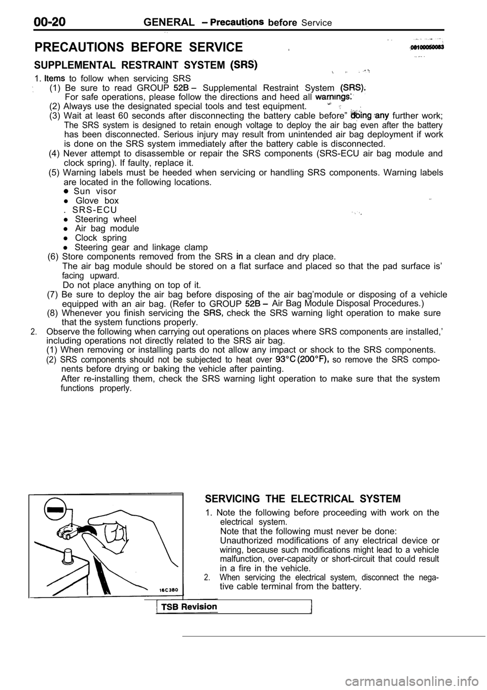
Note that the following must never be done:
Unauthorized modifications of any electrical device or
wiring, because such modifications might lead to a vehicle
malfunction, over-capacity or short-circuit that co uld result
in a fire in the vehicle.
2.When servicing the electrical system, disconnect th e nega-
tive cable terminal from the battery.
Page 24 of 2103
GENERAL Towing and Hoisting
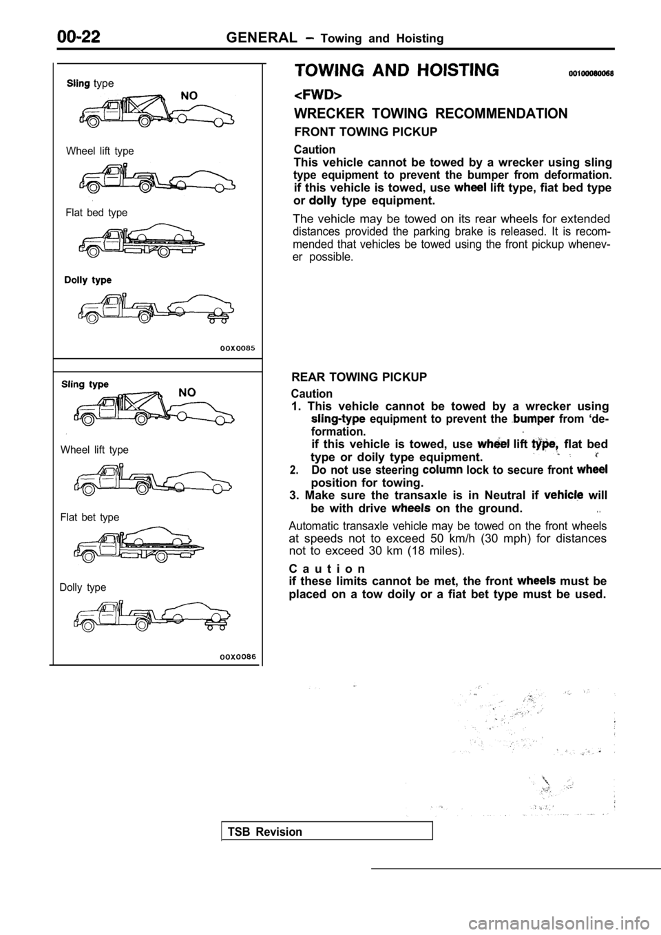
type
Wheel lift type
Flat bed type
Wheel lift type
Flat bet type
Dolly type
WRECKER TOWING RECOMMENDATION
FRONT TOWING PICKUP
Caution
This vehicle cannot be towed by a wrecker using sli ng
type equipment to prevent the bumper from deformati on.
if this vehicle is towed, use lift type, fiat bed type
or
type equipment.
The vehicle may be towed on its rear wheels for ext ended
distances provided the parking brake is released. It is recom-
mended that vehicles be towed using the front picku p whenev-
er possible.
REAR TOWING PICKUP
Caution
1. This vehicle cannot be towed by a wrecker using
equipment to prevent the from ‘de-
formation.
if this vehicle is towed, use lift flat bed
type or doily type equipment.
2.Do not use steering lock to secure front
position for towing.
3. Make sure the transaxle is in Neutral if
will
be with drive
on the ground.. .
Automatic transaxle vehicle may be towed on the fro nt wheels
at speeds not to exceed 50 km/h (30 mph) for distan ces
not to exceed 30 km (18 miles).
C a u t i o n
if these limits cannot be met, the front
must be
placed on a tow doily or a fiat bet type must be us ed.
TSB Revision
Page 25 of 2103
GENERAL Towing and Hoisting
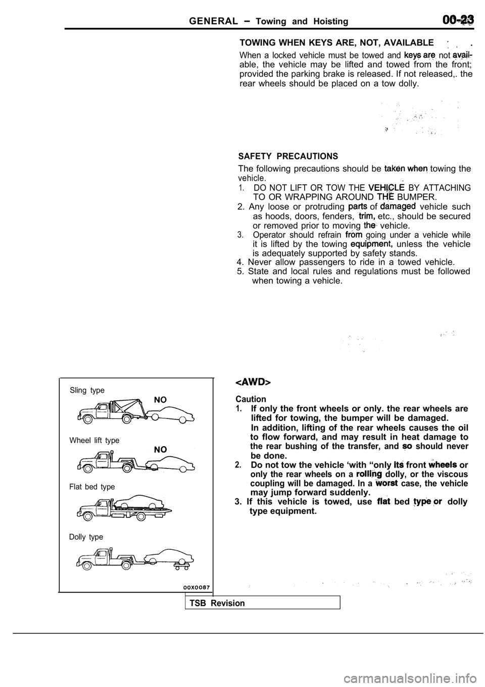
Sling type
Wheel lift type
Flat bed type
Dolly type
TOWING WHEN KEYS ARE, NOT, AVAILABLE .
When a locked vehicle must be towed and not
able, the vehicle may be lifted and towed from the front;
provided the parking brake is released. If not rele ased,. the
rear wheels should be placed on a tow dolly.
SAFETY PRECAUTIONS
The following precautions should be towing the
vehicle.
1.DO NOT LIFT OR TOW THE BY ATTACHING
TO OR WRAPPING AROUND BUMPER.
2. Any loose or protruding
of vehicle such
as hoods, doors, fenders,
etc., should be secured
or removed prior to moving
vehicle.
3.Operator should refrain going under a vehicle while
it is lifted by the towing unless the vehicle
is adequately supported by safety stands.
4. Never allow passengers to ride in a towed vehicl e.
5. State and local rules and regulations must be fo llowed
when towing a vehicle.
Caution
1.If only the front wheels or only. the rear wheels a re
lifted for towing, the bumper will be damaged.
In addition, lifting of the rear wheels causes the oil
to flow forward, and may result in heat damage to
the rear bushing of the transfer, and should never
be done.
2.Do not tow the vehicle ‘with “only front or
only the rear wheels on a dolly, or the viscous
coupling will be damaged. In a
case, the vehicle
may jump forward suddenly.
3. If this vehicle is towed, use
bed dolly
type equipment.
TSB Revision
Page 28 of 2103
G E N E R A L Special Handling AWD M o d e l s
0 0 0 0 3 6 8 5
0 0 1 0 0 7 4 0 0 1 0
Speedometer tests, brake tests and wheel balance me asure-
ment for full-time AWD vehicles should be carried o ut accord-
ing to the following procedures.
SPEEDOMETER TEST
Refer to GROUP 54 Combination Meter.
BRAKE TEST
In order to stabilize the viscous coupling‘s draggi ng force,
the brake test should always be conducted after the speedom-
eter test.
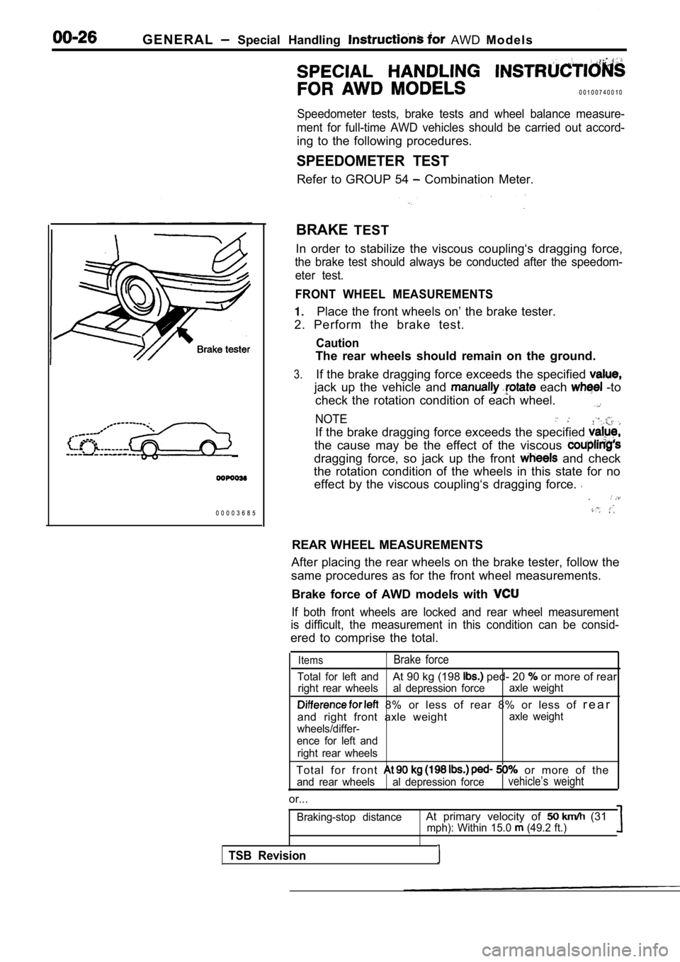
FRONT WHEEL MEASUREMENTS
Place the front wheels on’ the brake tester.
2. Perform the brake test.
Caution
The rear wheels should remain on the ground.
3.If the brake dragging force exceeds the specified
jack up the vehicle and each -to
check the rotation condition of each wheel.
NOTE
If the brake dragging force exceeds the specified
the cause may be the effect of the viscous
dragging force, so jack up the front and check
the rotation condition of the wheels in this state for no
effect by the viscous coupling‘s dragging force.
REAR WHEEL MEASUREMENTS
After placing the rear wheels on the brake tester, follow the
same procedures as for the front wheel measurements .
Brake force of AWD models with
If both front wheels are locked and rear wheel meas urement
is difficult, the measurement in this condition can be consid-
ered to comprise the total.
ItemsBrake force
Total for left andAt 90 kg (198 ped- 20 or more of rear
right rear wheels al depression forceaxle weight
8% or less of rear 8% or less of
r e a r
and right front axle weight
axle weight
wheels/differ-
ence for left and
right rear wheels
T o t a l f o r f r o n t or more of the
and rear wheels al depression forcevehicle’s weight
or...
Braking-stop distanceAt primary velocity of (31mph): Within 15.0 (49.2 ft.)
TSB Revision
Page 34 of 2103
GENERAL
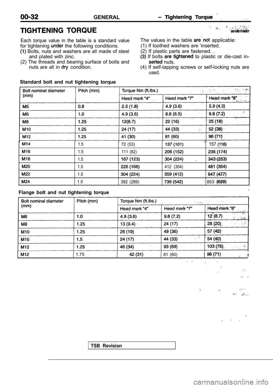
Each torque value in the table is a standard value
for tightening the following conditions.
Bolts, nuts and washers are all made of steeland plated with zinc.
(2) The threads and bearing surface of bolts and nuts are all in
condition. The values in the table
applicable:
(1) If toothed washers are ‘inserted.
(2) If plastic parts are fastened. .
If bolts to plastic or die-cast in-
nuts.
(4) If self-tapping screws or self-locking nuts are
used.
Standard bolt and nut tightening torque
1.5
1.5
1.5
1.5
1.5
1.5
Flange bolt and nut tightening torque
72 (53)157
111 (82)
412 (304)
392 (289) 853
1.7581 (60)
TSB Revision
Page 36 of 2103
Lubrication and
GENERAL Lubricants and Lubricant Capacities Table
Use of fuels containing alcohol is not recommended
unless the nature of the blend can be determined
as being satisfactory.
Gasohol
A mixture of 10% ethanol (grain alcohol)
and 90% unleaded gasoline may be used in your
car.
If problems are experienced as a result
of using gasohol, it is recommended that the car
be operated on gasoline.
Methanol Do not use gasolines containing
methanol (wood alcohol). Use of this type of alcohol
can result in vehicle performance deterioration and
damage critical parts in the fuel system compo-
nents. Fuel system damage and performance prob-
lems, resulting from the use of gasolines containin g
methanol, may not be covered by the new car war-
ranty.
Gasolines containing
Ether)
Unleaded gasoline containing 15% or
may be used in car. Fuel containing MTBE
over 15% vol. may cause reduced engine perfor-
mance and produce vapor lock or hard starting.
MATERIALS
TO FUEL
Indiscriminate use of fuel system -cleaning’
should be avoided. Many of these materials in-
tended for gum and varnish removal
highly active solvents or similar ingredients that
can be harmful to gasket and diaphragm materials
used in fuel system component
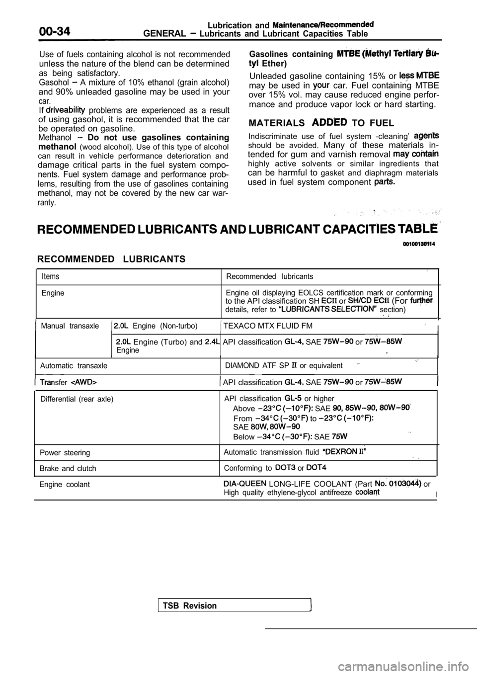
RECOMMENDED LUBRICANTS
Items
Engine
Recommended lubricants
Engine oil displaying EOLCS certification mark or c onforming
to the API classification SH or (For
details, refer to section)
Manual transaxle Engine (Non-turbo) TEXACO MTX FLUID FM I
Engine (Turbo) and API classification SAE or
Engine,
Automatic transaxle DIAMOND ATF SP or equivalent
TSB Revision
Transfer API classification SAE or
Differential (rear axle)API classification or higher
Above SAE
From to
SAE
Below SAE
Power steering
Brake and clutch Automatic transmission fluid
Conforming to or
Engine coolant LONG-LIFE COOLANT (Part or
High quality ethylene-glycol antifreeze I
Page 51 of 2103
GENERAL Maintenance
a
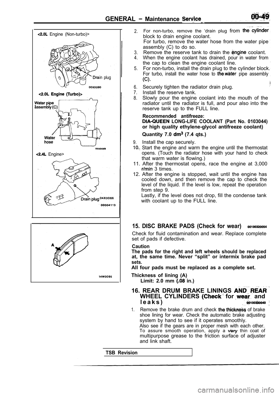
Engine (Non-turbo)>
in plug
Engine>
2.For non-turbo, remove the ‘drain plug from
block to drain engine coolant.
For turbo, remove the water hose from the water pip e
assembly (C) to do so.
3.
4.
5.Remove the reserve tank to drain the coolant.
When the engine coolant has drained, pour in water from
the cap to clean the engine coolant line.
For non-turbo, install the drain plug to the cylind er block.
For turbo, install the water hose to pipe assembly
6.
7.
8.
Securely tighten the radiator drain plug.
Install the reserve tank.
9.
Slowly pour the engine coolant into the mouth of th e
radiator until the radiator is full, and pour also into the
reserve tank up to the FULL line.
Recommended antifreeze:
LONG-LIFE COOLANT (Part No. 0103044)
or high quality ethylene-glycol antifreeze coolant)
Quantity 7.0
(7.4 qts.)
Install the cap securely.
Start the engine and warm the engine until the the rmostat
opens. (Touch the radiator hose with your hand to c heck
that warm water is flowing.)
11. After the thermostat opens, race the engine at 3,000
3 times.
12. After the engine is stopped, wait until the eng ine has
cooled down, and then remove the cap to check the
level of the liquid. If the level is low, repeat th e operation
from step 9.
Lastly, if the level does not drop, fill the conden se tank
with coolant up to the FULL line.
15. DISC BRAKE PADS (Check for wear)
Check for fluid contamination and wear. Replace com plete
set of pads if defective.
Caution
The pads for the right and left wheels should be re placed
at, the same time. Never “split” or intermix brake pad
sets.
All four pads must be replaced as a complete set.
Thickness of lining (A) Limit: 2.0 mm
in.)
16. REAR DRUM BRAKE LININGS
WHEEL CYLINDERS for and
l e a k s )
1.Remove the brake drum and check of brake
shoe lining for wear. Check the automatic brake adj usting
system by hand to see if it operates smoothly.
Also see if the gears are in proper mesh with each other.
To assure smooth operation, apply a thin coat of
multipurpose grease to the friction surface of adju ster
and link shaft.
TSB Revision