glove box MITSUBISHI SPYDER 1990 Service Repair Manual
[x] Cancel search | Manufacturer: MITSUBISHI, Model Year: 1990, Model line: SPYDER, Model: MITSUBISHI SPYDER 1990Pages: 2103, PDF Size: 68.98 MB
Page 22 of 2103
GENERAL before Service
PRECAUTIONS BEFORE SERVICE.
SUPPLEMENTAL RESTRAINT SYSTEM
1. to follow when servicing SRS
(1) Be sure to read GROUP Supplemental Restraint System
For safe operations, please follow the directions a nd heed all
(2) Always use the designated special tools and tes t equipment.
(3) Wait at least 60 seconds after disconnecting the battery cable before” further work;
The SRS system is designed to retain enough voltage to deploy the air bag even after the battery
has been disconnected. Serious injury may result from unintended air bag deployment if work
is done on the SRS system immediately after the bat tery cable is disconnected.
(4) Never attempt to disassemble or repair the SRS components (SRS-ECU air bag module and
clock spring). If faulty, replace it.
(5) Warning labels must be heeded when servicing or handling SRS components. Warning labels
are located in the following locations.
Sun visor
l Glove box
. S R S - E C U
l Steering wheel
l Air bag module
l Clock spring
l Steering gear and linkage clamp
(6) Store components removed from the SRS
a clean and dry place.
The air bag module should be stored on a flat surfa ce and placed so that the pad surface is’
facing upward.
Do not place anything on top of it.
(7) Be sure to deploy the air bag before disposing of the air bag’module or disposing of a vehicle
equipped with an air bag. (Refer to GROUP
Air Bag Module Disposal Procedures.)
(8) Whenever you finish servicing the
check the SRS warning light operation to make sure
that the system functions properly.
2.Observe the following when carrying out operations on places where SRS components are installed,’
.,
including operations not directly related to the SR S air bag.
(1) When removing or installing parts do not allow any impact or shock to the SRS components.
(2) SRS components should not be subjected to heat over so remove the SRS compo-
nents before drying or baking the vehicle after painting.
After re-installing them, check the SRS warning lig ht operation to make sure that the system
functions properly.
SERVICING THE ELECTRICAL SYSTEM
1. Note the following before proceeding with work o n the
electrical system.
Note that the following must never be done:
Unauthorized modifications of any electrical device or
wiring, because such modifications might lead to a vehicle
malfunction, over-capacity or short-circuit that co uld result
in a fire in the vehicle.
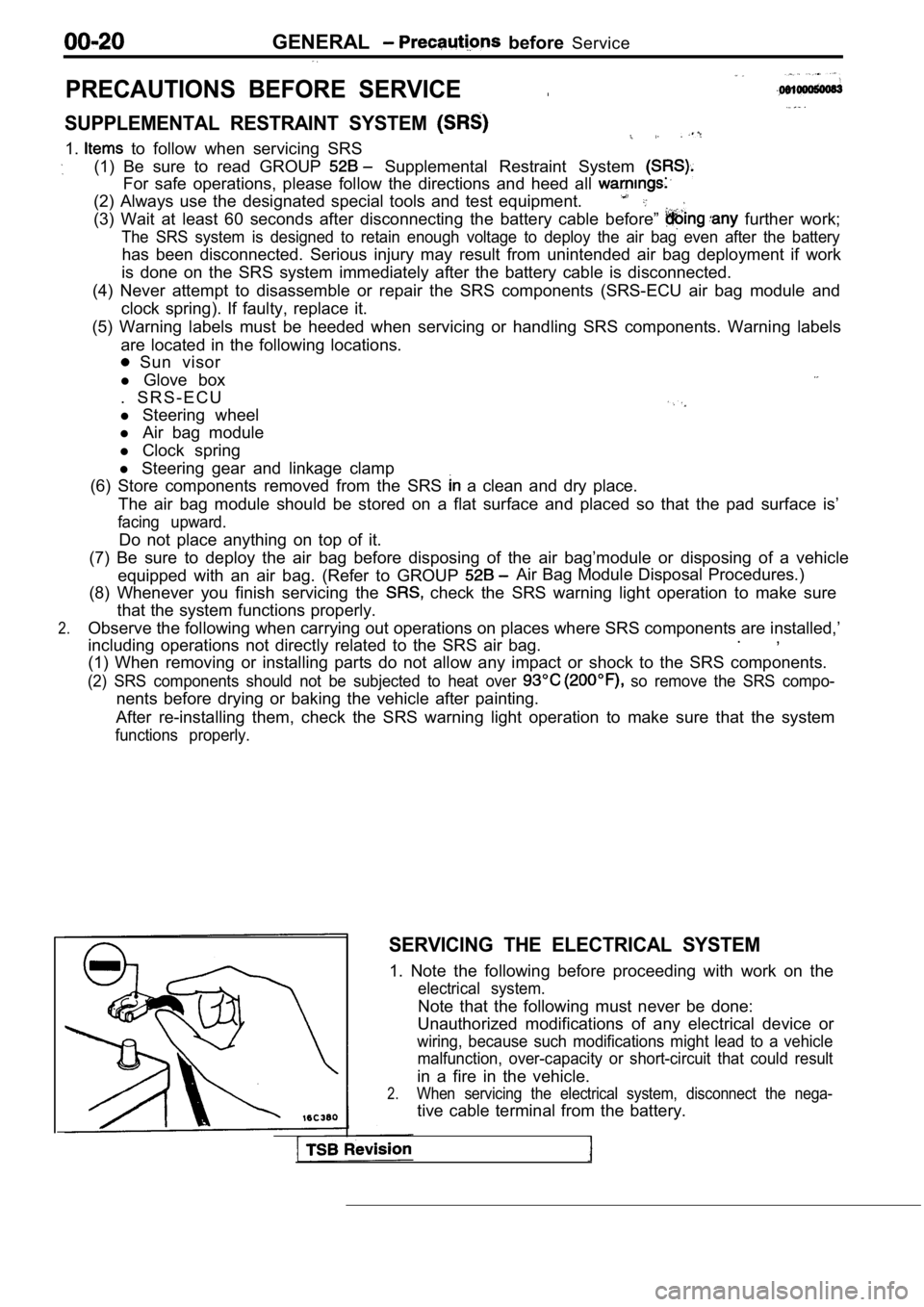
2.When servicing the electrical system, disconnect th e nega-
tive cable terminal from the battery.
Page 1961 of 2103
INTERIOR Instrument Panel
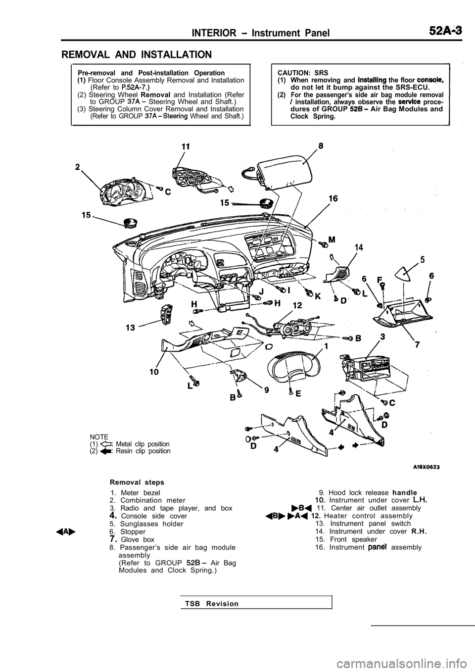
REMOVAL AND INSTALLATION
Pre-removal and Post-installation Operation Floor Console Assembly Removal and Installation(Refer to
(2) Steering Wheel Removaland Installation (Refer
to GROUP Steering Wheel and Shaft.)
(3) Steering Column Cover Removal and Installation
(Refer to GROUP Wheel and Shaft.)
CAUTION: SRS
(1) When removing and the floor do not let it bump against the SRS-ECU.(2)For the passenger’s side air bag module removal installation, always observe the proce-dures of GROUP Air Bag Modules andClock Spring.
14
5
NOTE
(1) Metal clip position
(2) Resin clip position
Removal steps
1. Meter bezel
2. Combination meter
3. Radio and tape player, and box
4. Console side cover
5. Sunglasses holder
6. Stopper 7. Glove box
8. Passenger’s side air bag module assembly(Refer to GROUP
Air Bag
Modules and Clock Spring.)
9. Hood lock release h a n d l e Instrument under cover 11. Center air outlet assembly 12. Heater control assembly
13. Instrument panel switch
14. Instrument under cover R . H .
15. Front speaker
16. Instrument
assembly
T S B R e v i s i o n
Page 1964 of 2103
INTERIOR
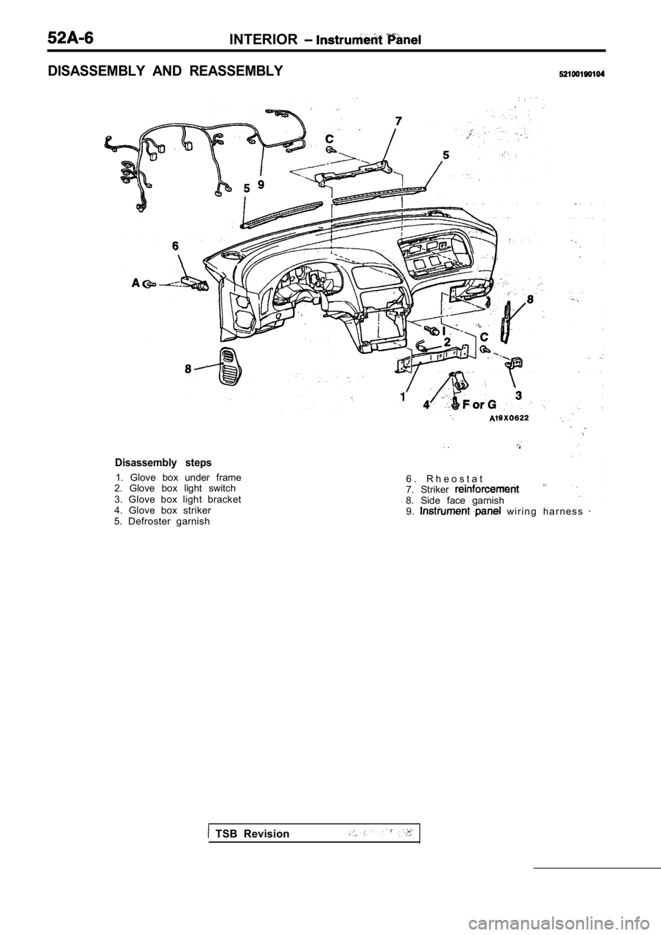
Disassembly steps
1. Glove box under frame
2. Glove box light switch
3. Glove box light bracket
4. Glove box striker
5. Defroster garnish
.
6 . R h e o s t a t
7. Striker
8. Side face garnish 9. w i r i n g h a r n e s s
DISASSEMBLY AND REASSEMBLY
TSB Revision
Page 1998 of 2103
SRS General Information
GENERAL INFORMATION
INTRODUCTION
The Supplemental Restraint System (SRS) is
signed to supplement the driver’s and front passen-
ger’s seat belts to help reduce the risk or severity
of injury to the driver and front passenger by acti vat-
ing and deploying both air bags in certain frontal
collisions.
The SRS consists of: two air bag modules; one
located in the center of the steering wheel and
another one located above the glove box, which
contains. the folded air bag and an inflator unit;
the SRS air bag control unit (SRS-ECU) located
under the floor console assembly, which monitors
the system, and which contains a safing
sensor
and analog
sensor; an SRS warning light located
on the instrument panel, which indicates the
tional status of the SRS; spring-interconnec-
tion located within the the
It is not until the SRS-ECU in response to the outp ut
signal from the analog sensor, finds it necessary
to ignite the air bag, and the safing sensor is
caused to be ON that the SRS deploys the air
bag.
Only authorized service personnel should do work
on or around SRS components. Those service per-
sonnel should read this manual carefully before
starting any such work. Extreme care must be used
when servicing the SRS, to avoid
to the ser-
vice personnel (by inadvertent deployment of the
air bag) or to driver (by rendering the SRS inopera -
tive).
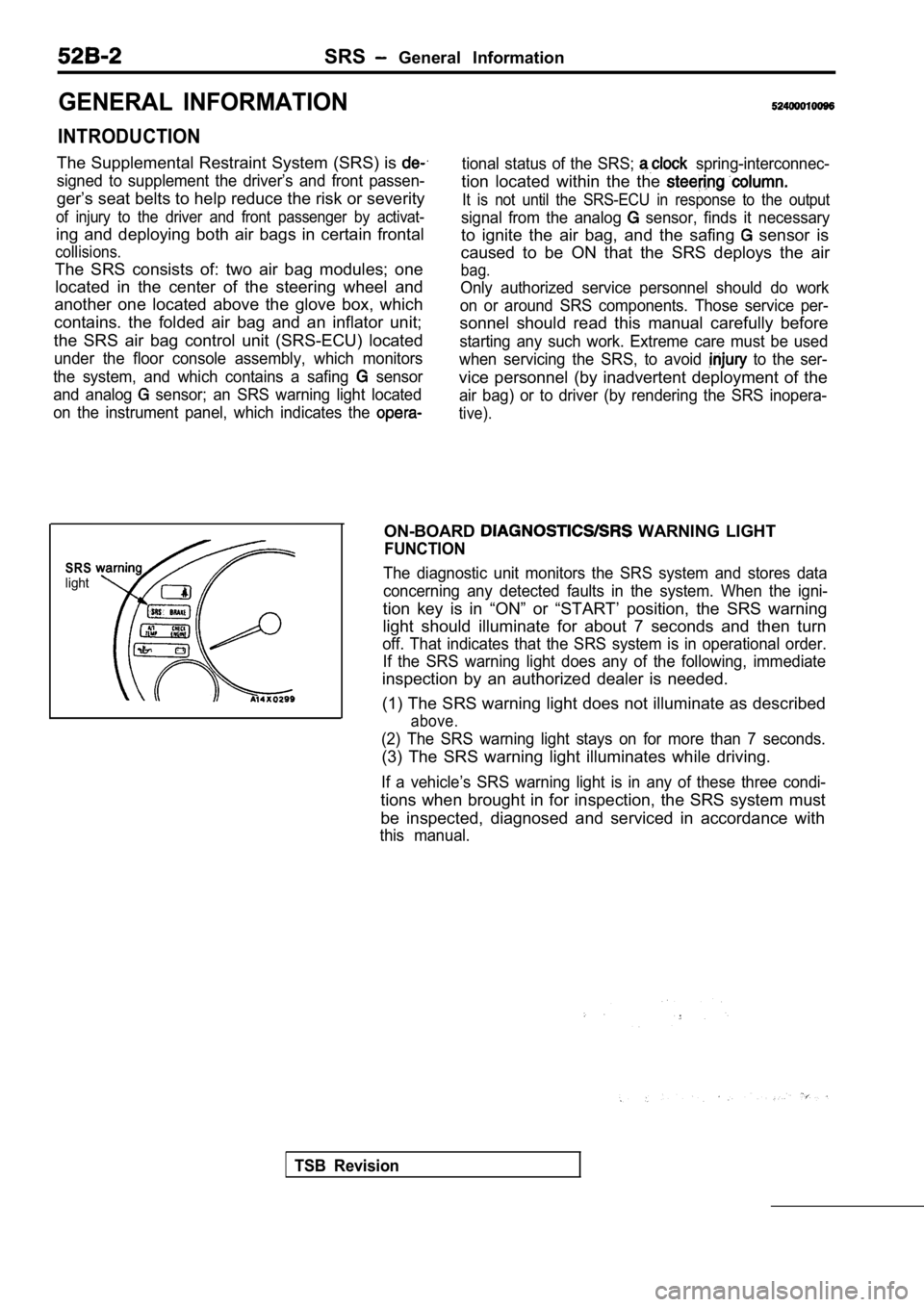
SRSlight
ON-BOARD WARNING LIGHT
FUNCTION
The diagnostic unit monitors the SRS system and sto res data
concerning any detected faults in the system. When the igni-
tion key is in “ON” or “START’ position, the SRS wa rning
light should illuminate for about 7 seconds and the n turn
off. That indicates that the SRS system is in operational order.
If the SRS warning light does any of the following, immediate
inspection by an authorized dealer is needed.
(1) The SRS warning light does not illuminate as de scribed
above.
(2) The SRS warning light stays on for more than 7 seconds.
(3) The SRS warning light illuminates while driving.
If a vehicle’s SRS warning light is in any of these three condi-
tions when brought in for inspection, the SRS syste m must
be inspected, diagnosed and serviced in accordance with
this manual.
TSB Revision
Page 2068 of 2103
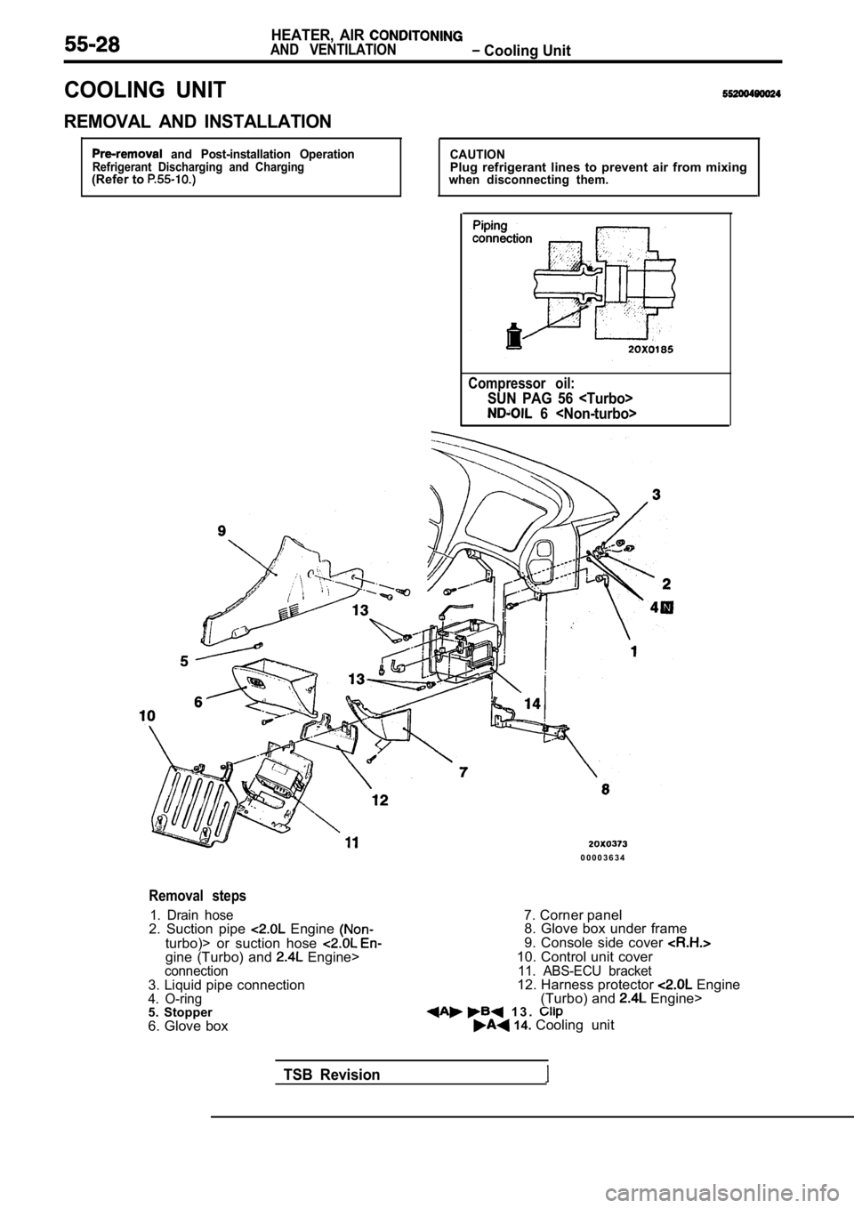
HEATER, AIR
AND VENTILATION Cooling Unit
COOLING UNIT
REMOVAL AND INSTALLATION
and Post-installation OperationRefrigerant Discharging and Charging(Refer to
CAUTIONPlug refrigerant lines to prevent air from mixingwhen disconnecting them.
Compressor oil:
SUN PAG 56
6
0 0 0 0 3 6 3 4
Removal steps
1. Drain hose2. Suction pipe Engine
turbo)> or suction hose gine (Turbo) and Engine>connection3. Liquid pipe connection4. O-ring5. Stopper
6. Glove box7. Corner panel
8. Glove box under frame
9. Console side cover
10. Control unit cover11. ABS-ECU bracket12. Harness protector Engine
(Turbo) and Engine> 1 3 . 14. Cooling unit
TSB Revision