parking brake MITSUBISHI SPYDER 1990 Service Repair Manual
[x] Cancel search | Manufacturer: MITSUBISHI, Model Year: 1990, Model line: SPYDER, Model: MITSUBISHI SPYDER 1990Pages: 2103, PDF Size: 68.98 MB
Page 24 of 2103
GENERAL Towing and Hoisting
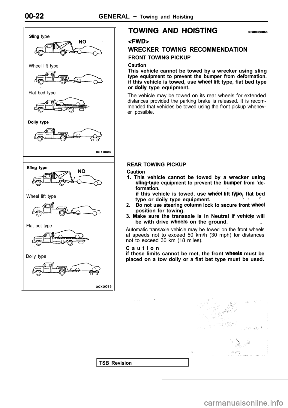
type
Wheel lift type
Flat bed type
Wheel lift type
Flat bet type
Dolly type
WRECKER TOWING RECOMMENDATION
FRONT TOWING PICKUP
Caution
This vehicle cannot be towed by a wrecker using sli ng
type equipment to prevent the bumper from deformati on.
if this vehicle is towed, use lift type, fiat bed type
or
type equipment.
The vehicle may be towed on its rear wheels for ext ended
distances provided the parking brake is released. It is recom-
mended that vehicles be towed using the front picku p whenev-
er possible.
REAR TOWING PICKUP
Caution
1. This vehicle cannot be towed by a wrecker using
equipment to prevent the from ‘de-
formation.
if this vehicle is towed, use lift flat bed
type or doily type equipment.
2.Do not use steering lock to secure front
position for towing.
3. Make sure the transaxle is in Neutral if
will
be with drive
on the ground.. .
Automatic transaxle vehicle may be towed on the fro nt wheels
at speeds not to exceed 50 km/h (30 mph) for distan ces
not to exceed 30 km (18 miles).
C a u t i o n
if these limits cannot be met, the front
must be
placed on a tow doily or a fiat bet type must be us ed.
TSB Revision
Page 25 of 2103
GENERAL Towing and Hoisting
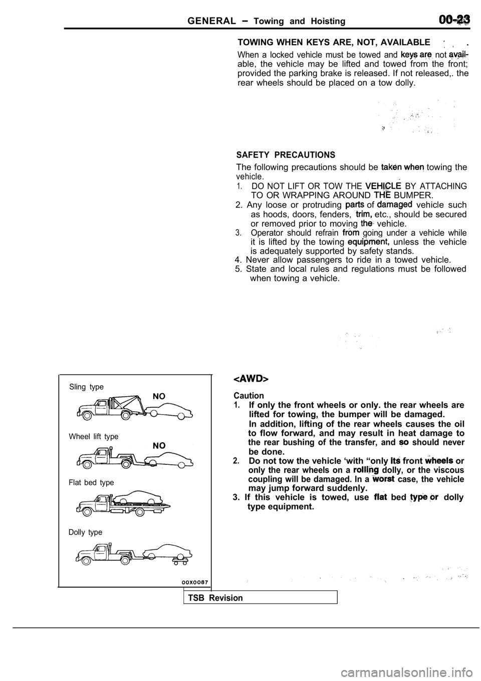
Sling type
Wheel lift type
Flat bed type
Dolly type
TOWING WHEN KEYS ARE, NOT, AVAILABLE .
When a locked vehicle must be towed and not
able, the vehicle may be lifted and towed from the front;
provided the parking brake is released. If not rele ased,. the
rear wheels should be placed on a tow dolly.
SAFETY PRECAUTIONS
The following precautions should be towing the
vehicle.
1.DO NOT LIFT OR TOW THE BY ATTACHING
TO OR WRAPPING AROUND BUMPER.
2. Any loose or protruding
of vehicle such
as hoods, doors, fenders,
etc., should be secured
or removed prior to moving
vehicle.
3.Operator should refrain going under a vehicle while
it is lifted by the towing unless the vehicle
is adequately supported by safety stands.
4. Never allow passengers to ride in a towed vehicl e.
5. State and local rules and regulations must be fo llowed
when towing a vehicle.
Caution
1.If only the front wheels or only. the rear wheels a re
lifted for towing, the bumper will be damaged.
In addition, lifting of the rear wheels causes the oil
to flow forward, and may result in heat damage to
the rear bushing of the transfer, and should never
be done.
2.Do not tow the vehicle ‘with “only front or
only the rear wheels on a dolly, or the viscous
coupling will be damaged. In a
case, the vehicle
may jump forward suddenly.
3. If this vehicle is towed, use
bed dolly
type equipment.
TSB Revision
Page 29 of 2103
GENERAL Special Handling Instructions for Models
W H E E L B A L A N C E,
FRONT WHEEL MEASUREMENTS
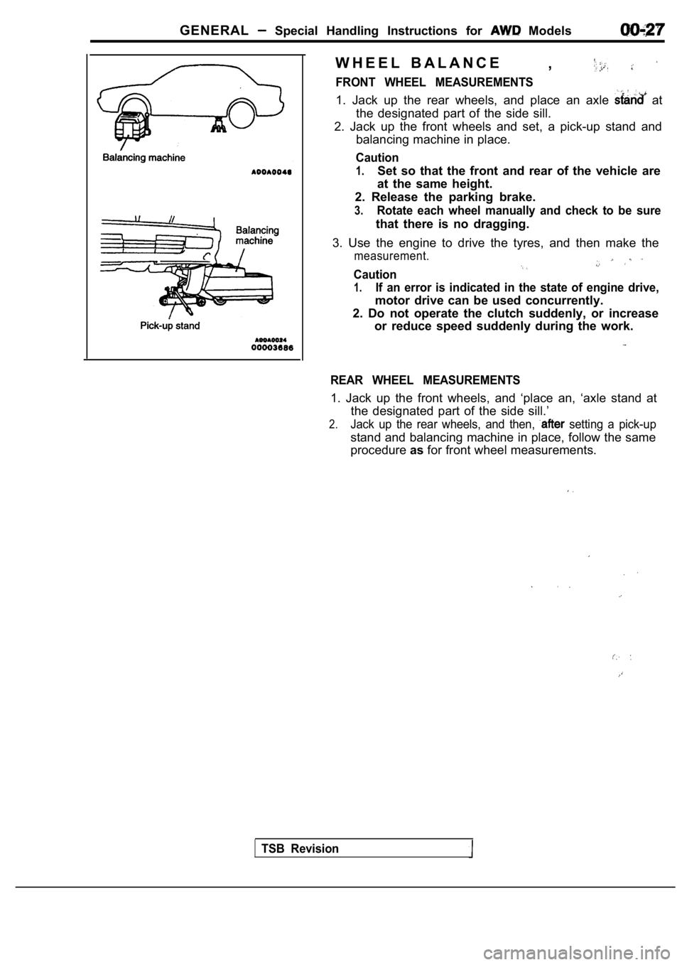
1. Jack up the rear wheels, and place an axle at
the designated part of the side sill.
2. Jack up the front wheels and set, a pick-up stan d and
balancing machine in place.
Caution
1.Set so that the front and rear of the vehicle are
at the same height.
2. Release the parking brake.
3.Rotate each wheel manually and check to be sure
that there is no dragging.
3. Use the engine to drive the tyres, and then make the
measurement.
Caution
1.If an error is indicated in the state of engine drive,
motor drive can be used concurrently.
2. Do not operate the clutch suddenly, or increase or reduce speed suddenly during the work.
REAR WHEEL MEASUREMENTS
1. Jack up the front wheels, and ‘place an, ‘axle s tand at
the designated part of the side sill.’
2.Jack up the rear wheels, and then, setting a pick-up
stand and balancing machine in place, follow the sa me
procedure asfor front wheel measurements.
TSB Revision
Page 49 of 2103
GENERALMaintenance Service
5.Add 3.8 (4.0 qts.) of the specified transmission fluid
through the filler tube.
Specified fluid:DIAMOND ATF SP IIor equivalent
6. Start the engine and allow it to run at idle for at least
one minute. Then, with parking and service brake ap plied,
move the selector lever momentarily to each positio n,
ending in the park or neutral position.
7.Add sufficient fluid to bring to’ inch below the
ADD mark.
8.Recheck fluid level after is normal operating
temperature. The level should be in the HOT region.
Engine (Turbo) and Engine>
Drain the fluid and check whether there is any evid ence of
contamination.
Refill with new fluid after the cause of any contam ination
has been corrected.
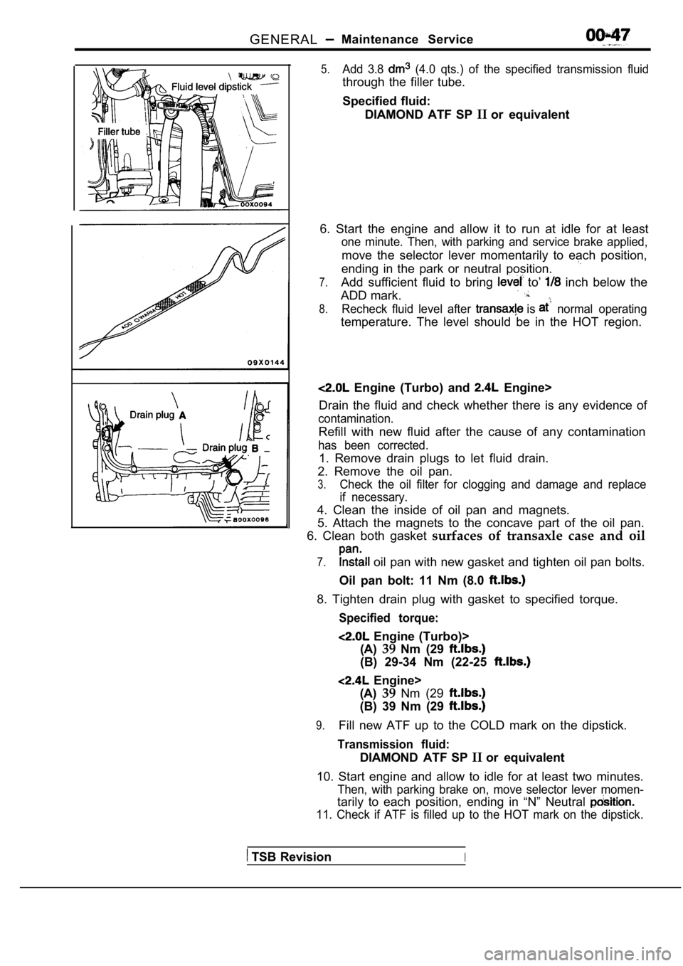
1. Remove drain plugs to let fluid drain.
2. Remove the oil pan.
3.Check the oil filter for clogging and damage and re place
if necessary.
4. Clean the inside of oil pan and magnets.
5. Attach the magnets to the concave part of the oi l pan.
6. Clean both gasket surfaces of transaxle case and oil
7. oil pan with new gasket and tighten oil pan bolts.
Oil pan bolt: 11 Nm (8.0
8. Tighten drain plug with gasket to specified torq ue.
Specified torque:
Engine (Turbo)>
(A) 39Nm (29
(B) 29-34 Nm (22-25
Engine>
(A) 39Nm (29
(B) 39 Nm (29
9.Fill new ATF up to the COLD mark on the dipstick.
Transmission fluid:
DIAMOND ATF SP IIor equivalent
10. Start engine and allow to idle for at least two minutes.
Then, with parking brake on, move selector lever mo men-
tarily to each position, ending in “N” Neutral
11. Check if ATF is filled up to the HOT mark on the dipstick.
TSB RevisionI
Page 836 of 2103
CLUTCH On-vehicle Service
Interlock switch
Revision
INTERLOCK SWITCH OPERATING CHECK
1.
2.
Lock the front wheels, apply the parking brake and put
the shift lever in the
gear.
After normally adjusting the clutch pedal, check th e inter-
lock switch operation as follows:
(1) The engine should not start even if the ignition switch
is turned to “START” position with the clutch pedal
not depressed. If the engine should start, check th e
interlock switch
harness.
(2) The engine should start after the clutch has be en
disconnected while the clutch pedal is depressed with
the ignition switch turned to “START” position.
If the engine should start before the clutch pedal
is disconnected or the engine does not start even
if the clutch pedal is depressed, adjust the interl ock
switch.
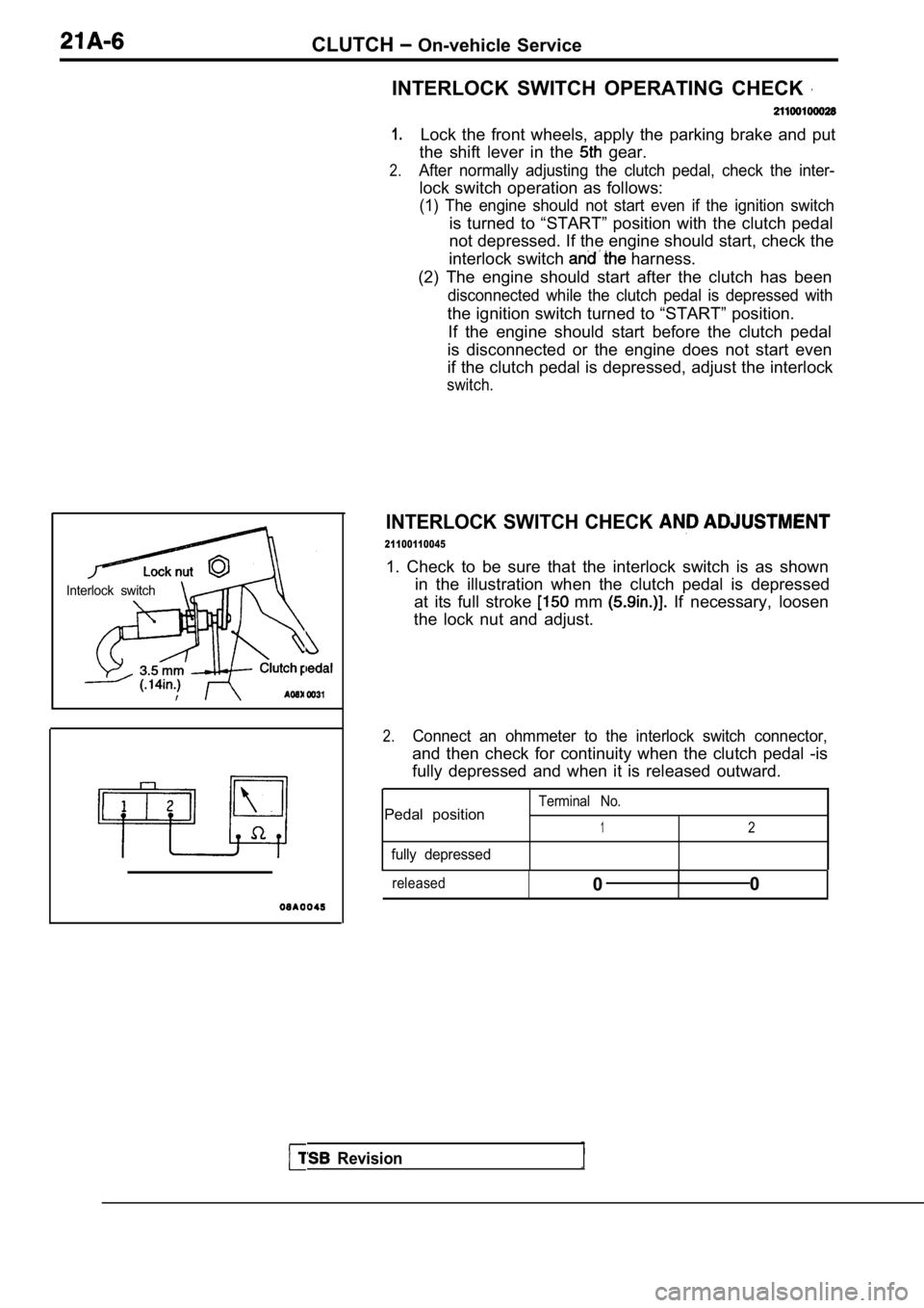
INTERLOCK SWITCH CHECK
21100110045
1. Check to be sure that the interlock switch is as shown
in the illustration when the clutch pedal is depres sed
at its full stroke
mm If necessary, loosen
the lock nut and adjust.
2.Connect an ohmmeter to the interlock switch connect or,
and then check for continuity when the clutch pedal -is
fully depressed and when it is released outward.
Terminal No.Pedal position12
fully depressed
released0I0
Page 1072 of 2103
AUTOMATIC TRANSAXLE
ENGINE (TURBO) AND On-vehicle Service
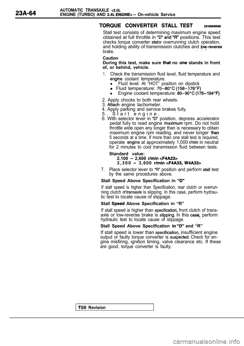
Stall test consists of determining maximum engine speed
obtained at full throttle in positions. This test
checks torque converter overrunning clutch operation,
and holding ability of transmission clutches and
brake.
Caution
During this test, make sure no stands in front
of, or behind, vehicle.
1.Check the transmission fluid level, fluid temperatu re and
coolant temperature.
lFluid level: At “HOT” position on dipstick
l Fluid temperature:
lEngine coolant temperature:
2. Apply chocks to both rear wheels.
3.
engine tachometer.
4. Apply parking and service brakes fully.
5 . S t a r t e n g i n e .
6. With selector lever in position, depress accelerator
pedal fully to read engine
rpm. Do not hold
throttle wide open any longer than is necessary to obtain
maximum engine rpm reading, and never longer
5 seconds at a time. If more than one stall test is required,
operate at approximately 1,000 in neutral
for 2 minutes to cool transmission fluid between te sts.
Standard value:
TSB Revision
2,100 2,600
3 , 3 0 0 3 , 6 0 0
7.Place selector lever to position and perform test
by the same procedures above.
Stall Speed Above Specification in
If stall speed is higher than Specification, rear c lutch or overrun-
ning clutch is slipping. In this case, perform hydrau-
lic test to locate cause of slippage.
Stall Above Specification in “R”
If stall speed is higher than front clutch of trans-
axle or low-reverse brake is In this perform
hydraulic test to locate cause of slippage.
Stall Speed Above Specification and “R”
If stall speed is lower than insufficient engine
output or faulty torque converter is Check for en-
gine misfiring, ignition timing, valve clearance etc. If these
are good, torque converter is faulty..
Page 1174 of 2103
AUTOMATIC TRANSAXLE
ENGINE (NON-TURBO)> On-vehicle Service
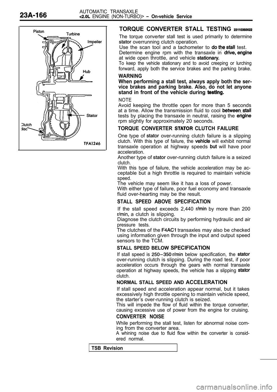
TORQUE CONVERTER STALL TESTING
The torque converter stall test is used primarily to determine
overrunning clutch operation.
Use the scan tool and a tachometer to
test.
Determine engine rpm with the transaxle in
at wide open throttle, and vehicle
To keep the vehicle stationary and to avoid creepin g or lurching
forward, apply both the service brakes and the parking brake.
WARNING
When performing a stall test, always apply both the ser-
vice brakes and parking brake. Also, do not let any one
stand in front of the vehicle during
NOTE
Avoid keeping the throttle open for more than 5 seconds
at a time. Allow the transmission fluid to cool
tests by placing the transaxle in neutral, raising the
rpm slightly for approximately 20 seconds.
TORQUE CONVERTER CLUTCH FAILURE
One type of over-running clutch failure is a slipping
clutch. With this type of failure, the will exhibit normal
transaxle operation at highway speeds will have poor
acceleration.
Another type of over-running clutch failure is a seized
clutch.
With this type of failure, the vehicle acceleration may be ac-
ceptable but a high throttle is required to maintai n vehicle
speed.
The vehicle may seem like it has a loss of power.
With either type of failure, poor fuel economy and transaxle
fluid over-hearting may be the result.
STALL SPEED ABOVE SPECIFICATION
If the stall speed exceeds 2,440 by more than 200
a clutch is slipping.
Diagnose the clutch circuits by performing hydrauli c and air
pressure tests.
The clutches of the transaxles may also be checked
using information given through the input and outpu t speed
sensors to the TCM.
STALL SPEED BELOW SPECIFICATION
If stall speed is below specification, the
over-running clutch is slipping. During the road te st, if poor
acceleration occurs through the gears with normal t ransaxle
operation at highway speeds, the vehicle has a slip ping
clutch.
NORMAL STALL SPEED AND ACCELERATION
If stall speed and acceleration appear normal, but it takes
excessively high throttle opening to maintain vehic le speed,
the starter’s over-running clutch is seized.
This will impede the flow of fluid within the torqu e converter,
causing excessive use of power from the engine for cruising.
CONVERTER NOISE
While performing the stall test, listen for abnormal noise com-
ing from the converter area.
A whining noise due to fluid flow within the conver ter is consid-
ered normal.
TSB Revision
Page 1537 of 2103
REAR AXLE . .
Symptom
Abnormal
Probable cause
Loose wheel nuts
Damaged or worn wheel
Bentordistorted brake discs
Remedy
Tighten Replace
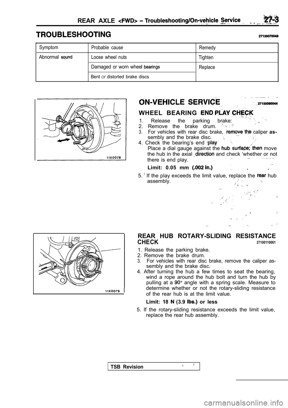
WHEEL BEARING
1. Release the parking brake: ,
2. Remove the brake drum.
3.For vehicles with rear disc brake, caliper as-
sembly and the brake disc.
4. Check the bearing’s end
Place a dial gauge against the move
the hub in the axial
and check ‘whether or not
there is end play. .
.
Limit: 0.05 mm .
5.
If the play exceeds the limit value, replace the hub
assembly.
.
REAR HUB ROTARY-SLIDING RESISTANCE
CHECK27100110061
1. Release the parking brake.
2. Remove the brake drum.
3.For vehicles with rear disc brake, remove the calip er as-
sembly and the brake disc.
4. After turning the hub a few times to seat the be aring,
wind a rope around the hub bolt and turn the hub by pulling at a
angle with a spring scale. Measure to
determine whether or not the rotary-sliding resista nce
of the rear hub is at the limit value.
Limit: 18
(3.9 or less
5. If the rotary-sliding resistance exceeds the lim it value,
replace the rear hub assembly.
TSB Revision
Page 1539 of 2103
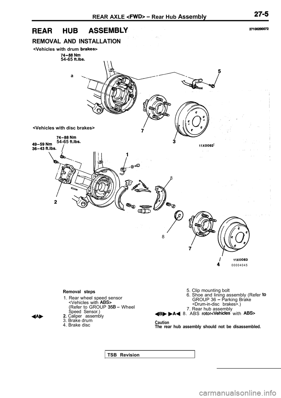
REAR AXLE Rear Hub Assembly
REMOVAL AND INSTALLATION
a
54-65
8
8
0 0 0 0 4 0 4 5
Removal steps
1. Rear wheel speed sensor
4. Brake disc 5. Clip mounting bolt
6. Shoe and lining assembly (Refer
GROUP 36 Parking Brake
7. Rear hub assembly 8. ABS with
CautionThe rear hub assembly should not be disassembled.
TSB Revision
Page 1550 of 2103
6REAR AXLE Service
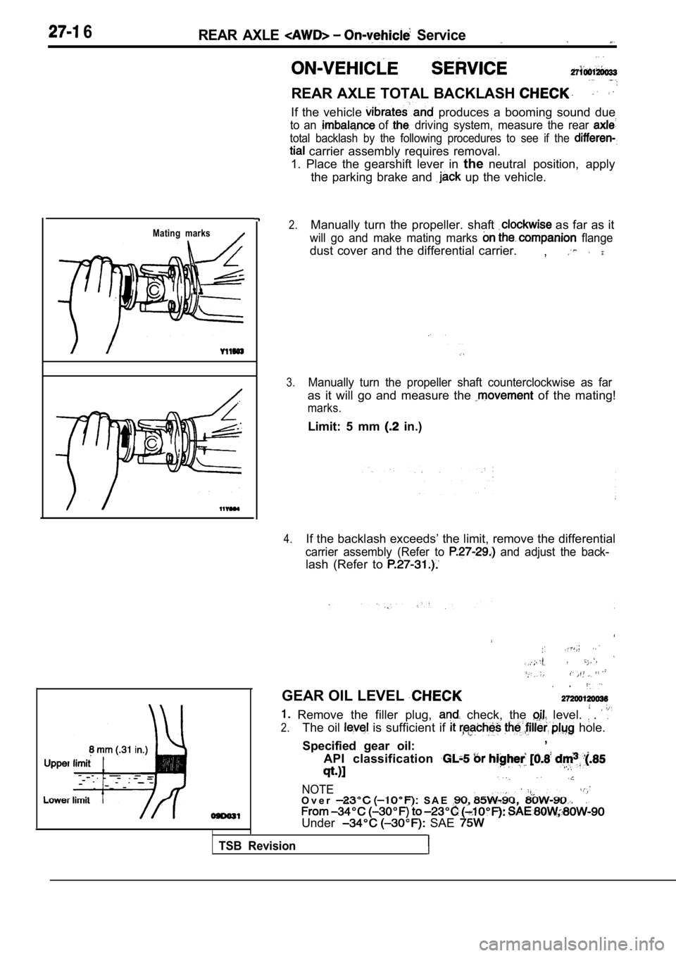
REAR AXLE TOTAL BACKLASH
If the vehicle produces a booming sound due
to an of driving system, measure the rear
total backlash by the following procedures to see if the
carrier assembly requires removal.
1. Place the gearshift lever in theneutral position, apply
the parking brake and
up the vehicle.
Mating marks2.Manually turn the propeller. shaft as far as it
will go and make mating marks flange
dust cover and the differential carrier. ,
3.Manually turn the propeller shaft counterclockwise as far
as it will go and measure the of the mating!
marks.
Limit: 5 mm in.)
4.If the backlash exceeds’ the limit, remove the differential
carrier assembly (Refer to and adjust the back-
lash (Refer to
TSB Revision
GEAR OIL LEVEL
Remove the filler plug, check, the level. .
2.The oil is sufficient if hole.
Specified gear oil: ,
API classification
NOTEO v e r S A E
Under SAE