parking brake MITSUBISHI SPYDER 1990 Service User Guide
[x] Cancel search | Manufacturer: MITSUBISHI, Model Year: 1990, Model line: SPYDER, Model: MITSUBISHI SPYDER 1990Pages: 2103, PDF Size: 68.98 MB
Page 1551 of 2103
REAR AXLE On-vehicle Service
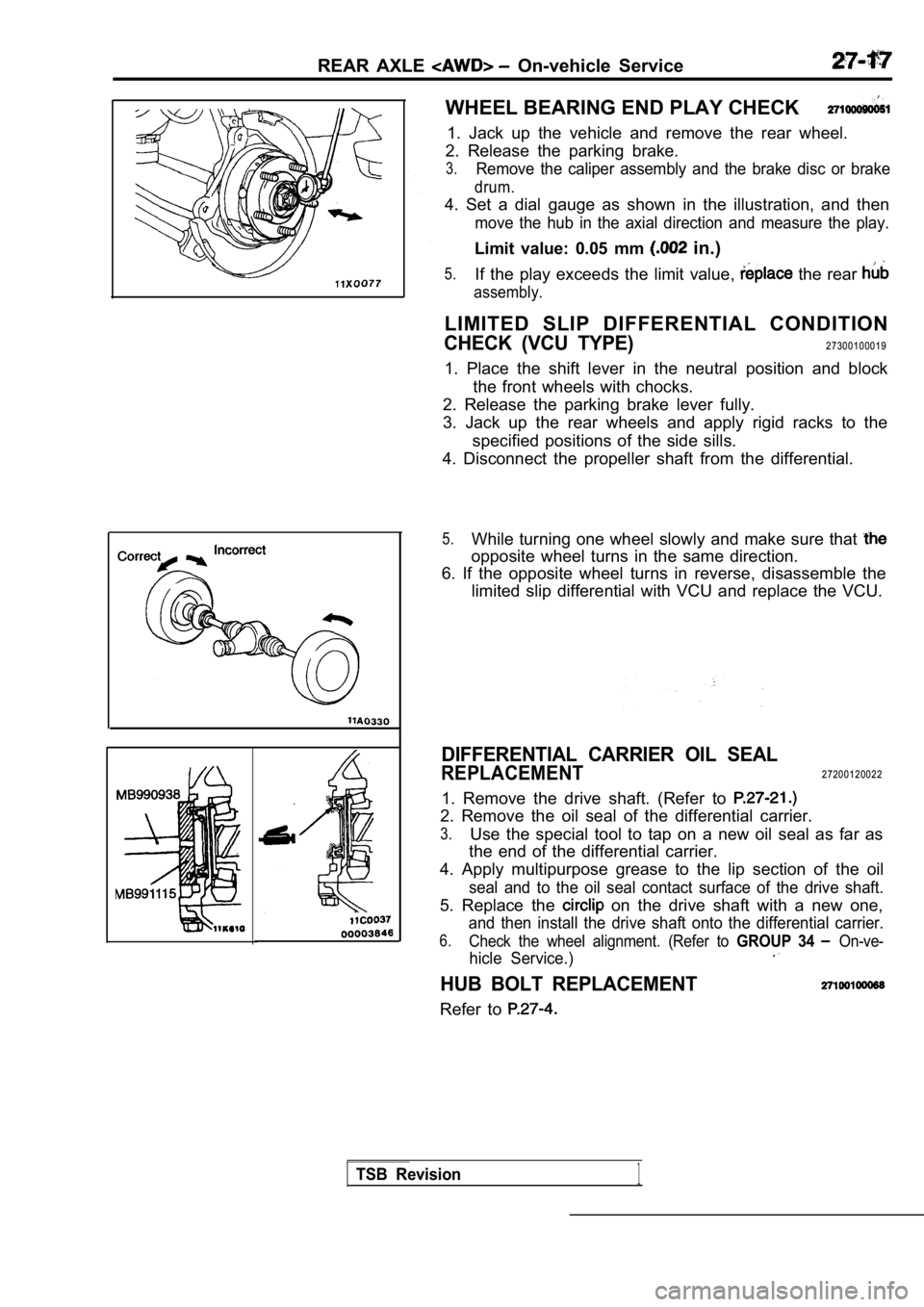
WHEEL BEARING END PLAY CHECK
1. Jack up the vehicle and remove the rear wheel.
2. Release the parking brake.
3.Remove the caliper assembly and the brake disc or b rake
drum.
4. Set a dial gauge as shown in the illustration, and then
move the hub in the axial direction and measure the play.
Limit value: 0.05 mm in.)
5.If the play exceeds the limit value, the rear
assembly.
LIMITED SLIP DIFFERENTIAL CONDITION
CHECK (VCU TYPE)27300100019
1. Place the shift lever in the neutral position an d block
the front wheels with chocks.
2. Release the parking brake lever fully.
3. Jack up the rear wheels and apply rigid racks to the
specified positions of the side sills.
4. Disconnect the propeller shaft from the differen tial.
5.While turning one wheel slowly and make sure that
opposite wheel turns in the same direction.
6. If the opposite wheel turns in reverse, disassem ble the
limited slip differential with VCU and replace the VCU.
DIFFERENTIAL CARRIER OIL SEAL
REPLACEMENT27200120022
1. Remove the drive shaft. (Refer to
2. Remove the oil seal of the differential carrier.
3.Use the special tool to tap on a new oil seal as fa r as
the end of the differential carrier.
4. Apply multipurpose grease to the lip section of the oil
seal and to the oil seal contact surface of the drive shaft.
5. Replace the on the drive shaft with a new one,
and then install the drive shaft onto the differential carrier.
6.Check the wheel alignment. (Refer to GROUP 34 On-ve-
hicle Service.)
HUB BOLT REPLACEMENT
Refer to
TSB Revision1
Page 1552 of 2103
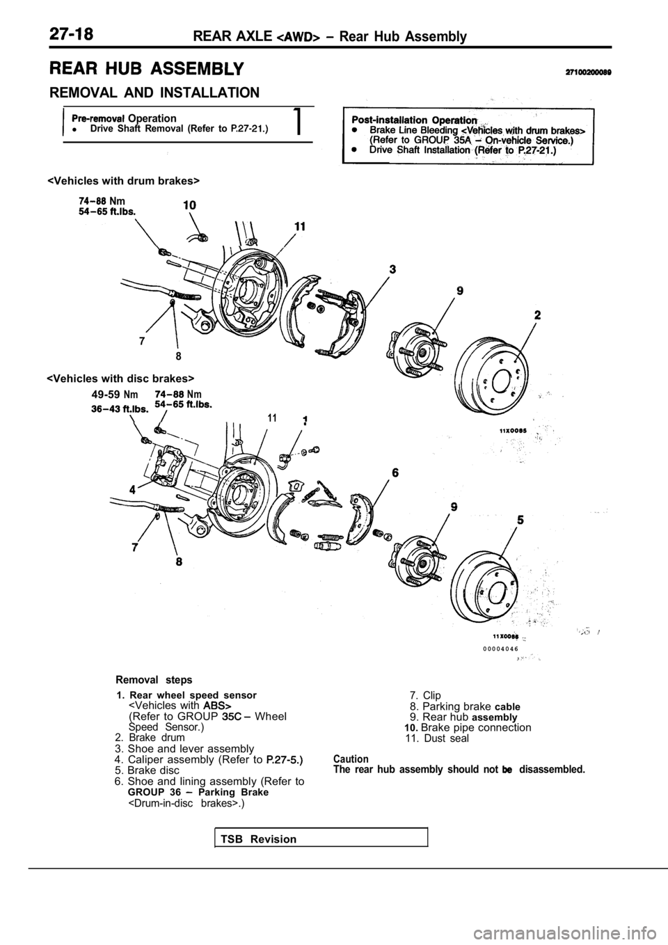
REAR AXLE Rear Hub Assembly
REMOVAL AND INSTALLATION
OperationlDrive Shaft Removal (Refer to 1
Nm
7
8
NmNm
11
Removal steps
1. Rear wheel speed sensor
2. Brake drum
3. Shoe and lever assembly
4. Caliper assembly (Refer to
5. Brake disc
6. Shoe and lining assembly (Refer to GROUP 36
Parking Brake
0 0 0 0 4 0 4 6
7. Clip8. Parking brake cable
9. Rear hub assembly
10. Brake pipe connection
11. Dust seal
CautionThe rear hub assembly should not disassembled.
TSB Revision
Page 1555 of 2103
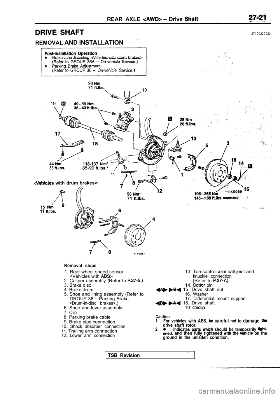
REAR AXLE Drive
2 7 1 0 0 3 3 0 0 2 3
REMOVAL AND INSTALLATION
Brake Line Bleeding with drum brakes>
(Refer to GROUP 36
On-vehicle Service.)
9871
I I10
,19
44118-1373385-99
11
with drum brakes>
11
9871. .,
Removal steps
1. Rear wheel speed sensor
4. Brake drum
5. Shoe and lining assembly (Refer to
GROUP 36
Parking Brake
7. Clip8. Parking brake cable
9. Brake pipe connection
10. Shock absorber connection Trailing arm connection12. Lower arm connection
13. Toe control armball joint andknuckle connection(Refer to 14. pin 15. Drive shaft nut16. Washer
17. Differential mount support
18. Drive shaft
19.
Caution1.For vehicles with ABS, careful not to damagedrive shaft rotor.2.l : Indicates parts should be temporarily and then fully tightened the on the
ground in the unladen condition.
TSB Revision
Page 1563 of 2103
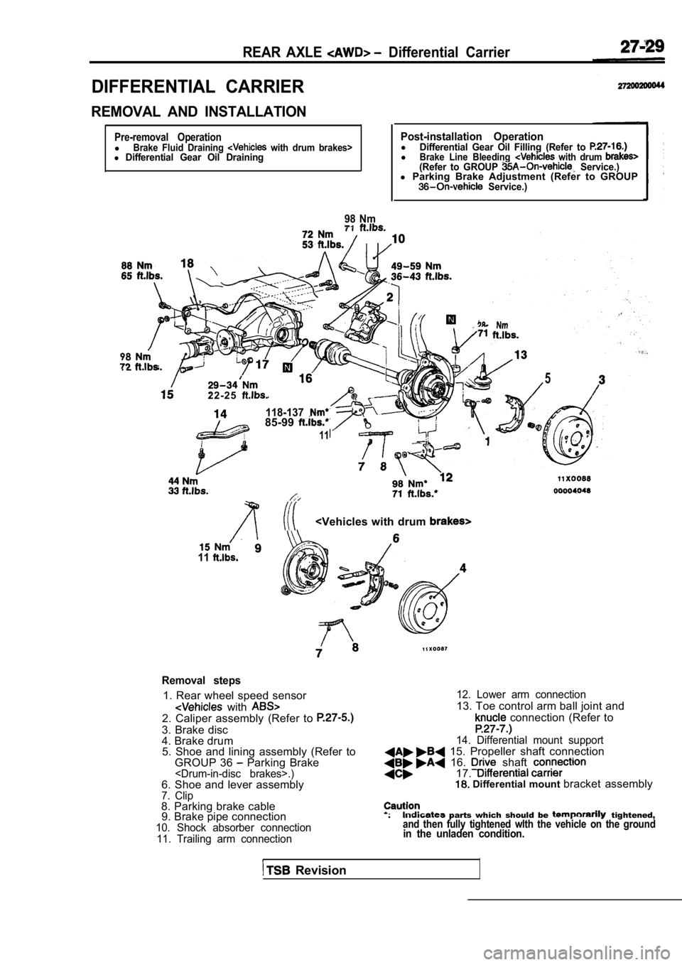
REAR AXLE Differential Carrier
DIFFERENTIAL CARRIER
REMOVAL AND INSTALLATION
Pre-removal OperationlBrake Fluid Draining with drum brakes>l Differential Gear Oil Draining
98 Nm
Post-installation OperationlDifferential Gear Oil Filling (Refer to lBrake Line Bleeding with drum (Refer to GROUP Service.)l Parking Brake Adjustment (Refer to GROUP Service.)
98
2 2 - 2 5
118-13785-99
11
5
11
Removal steps
1. Rear wheel speed sensor
with 2. Caliper assembly (Refer to
3. Brake disc
4. Brake drum
5. Shoe and lining assembly (Refer to
GROUP 36
Parking Brake
10. Shock absorber connection
11. Trailing arm connection 12. Lower arm connection
13. Toe control arm ball joint and
connection (Refer to
14. Differential mount support 15. Propeller shaft connection 16. shaft 17. Differential mount
bracket assembly
parts which should be tightened,and then fully tightened wlth the vehicle on the gr oundin the unladen condition.
Revision
Page 1623 of 2103
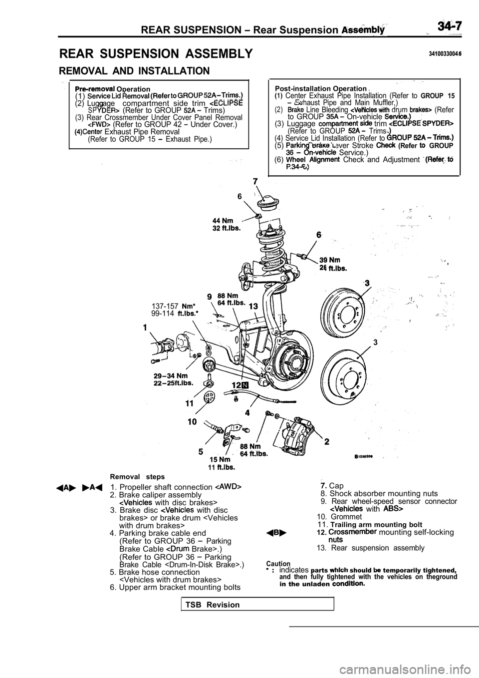
REAR SUSPENSION Rear Suspension
REAR SUSPENSION ASSEMBLY
REMOVAL AND INSTALLATION
Operation
(1)
(2) Lug agecompartment side trim SP (Refer to GROUP Trims)(3) Rear Crossmember Under Cover Panel Removal (Refer to GROUP 42 Under Cover.) Exhaust Pipe Removal(Refer to GROUP 15 Exhaust Pipe.)
3410033004
Post-installation Operation Center Exhaust Pipe Installation (Refer to GROUP 15Exhaust Pipe and Main Muffler,)(2) Line Bleeding drum (Referto GROUP On-vehicle (3) Luggage trim (Refer to GROUP Trims.
(4) Service Lid Installation (Refer to
(5) Brake Lever Stroke (Refer GROUP Service.)
(6) Check and Adjustment .
6
,
137-15799-114
.
l. .
3
Removal steps
11
1. Propeller shaft connection 2. Brake caliper assembly with disc brakes>
3. Brake disc with disc
brakes> or brake drum
4. Parking brake cable end
(Refer to GROUP 36
ParkingBrake Cable Brake>.)
(Refer to GROUP 36
ParkingBrake Cable
6. Upper arm bracket mounting bolts
Cap
8. Shock absorber mounting nuts
9. Rear wheel-speed sensor connector with 10. Grommet11. Trailing arm mounting bolt
12. mounting self-locking
13. Rear suspension assembly
Cautionindicatesparts should temporarily tightened,and then fully tightened with the vehicles on thegr oundin the unladen
TSB Revision
Page 1643 of 2103
BASIC BRAKE SYSTEM Troubleshooting
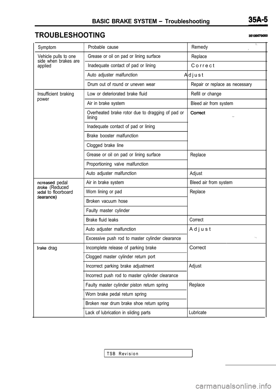
TROUBLESHOOTING
SymptomProbable cause
Remedy
Vehicle pulls to oneGrease or oil on pad or lining surface
Replace
side when brakes are
applied Inadequate contact of pad or lining
C o r r e c t
Auto adjuster malfunctionA d j u s t
Drum out of round or uneven wear Repair or replace a
s necessary
Insufficient braking Low or deteriorated brake fluid Refill or change
power Air in brake system Bleed air from system
Overheated brake rotor due to dragging of pad or
lining
Inadequate contact of pad or lining
Brake booster malfunction
Clogged brake line
pedal
(Reduced
to floorboard
drag
Grease or oil on pad or lining surface
Proportioning valve malfunction
Auto adjuster malfunction
Air in brake system
Worn lining or pad
Broken vacuum hose
Faulty master cylinder
Brake fluid leaks
Auto adjuster malfunction Excessive push rod to master cylinder clearance
Incomplete release of parking brake
Clogged master cylinder return port
Incorrect parking brake adjustment
Incorrect push rod to master cylinder clearance
Faulty master cylinder piston return spring
Worn brake pedal return spring
Broken rear drum brake shoe return spring Replace
Adjust Bleed air from system
Replace
Correct
A d j u s t
Correct
Adjust Replace
Lack of lubrication in sliding parts Lubricate
T S B R e v i s i o n
Page 1644 of 2103
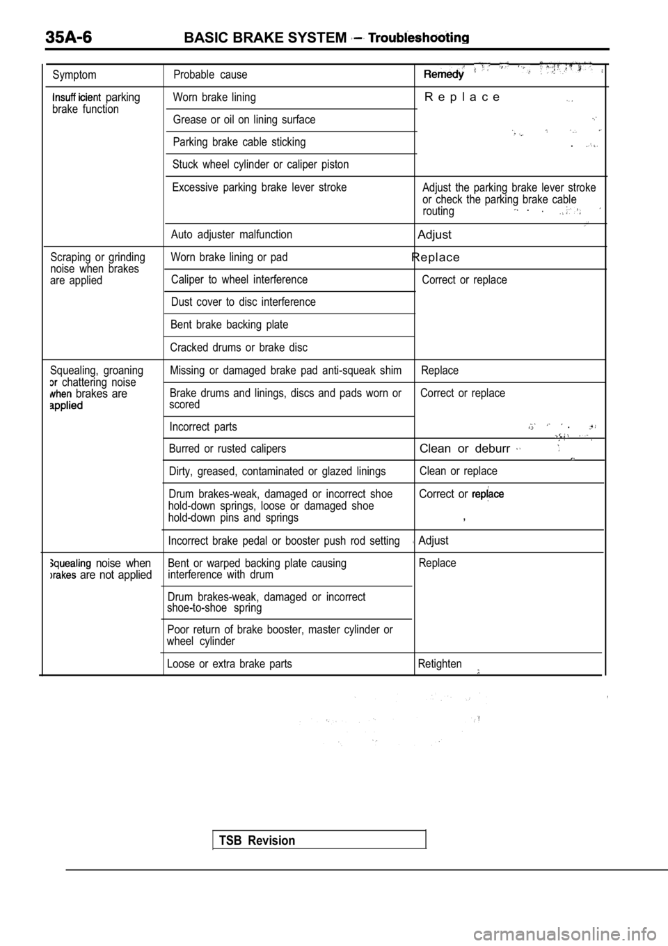
BASIC BRAKE SYSTEM
Symptom
parking
brake functionProbable cause
Worn brake lining
R e p l a c e
Grease or oil on lining surface
Parking brake cable sticking
Stuck wheel cylinder or caliper piston.
Scraping or grinding
noise when brakes
are applied Excessive parking brake lever stroke
Auto adjuster malfunction
Worn brake lining or pad Caliper to wheel interference
Dust cover to disc interference Adjust the parking brake lever stroke
or check the parking brake cable
routing
.
Adjust
R e p l a c e
Correct or replace
Bent brake backing plate
Cracked drums or brake disc
Squealing, groaning
chattering noise
brakes are
Missing or damaged brake pad anti-squeak shim Replac e
Brake drums and linings, discs and pads worn or Corr ect or replace
scored
Incorrect parts
.
Burred or rusted calipersClean or deburr
Dirty, greased, contaminated or glazed linings Clean or replace
Drum brakes-weak, damaged or incorrect shoe
hold-down springs, loose or damaged shoe
Correct or
hold-down pins and springs,
Incorrect brake pedal or booster push rod setting Adjust
noise whenBent or warped backing plate causing Replace
are not appliedinterference with drum
Drum brakes-weak, damaged or incorrect
shoe-to-shoe spring
Poor return of brake booster, master cylinder or
wheel cylinder
Loose or extra brake parts Retighten
TSB Revision
Page 1678 of 2103
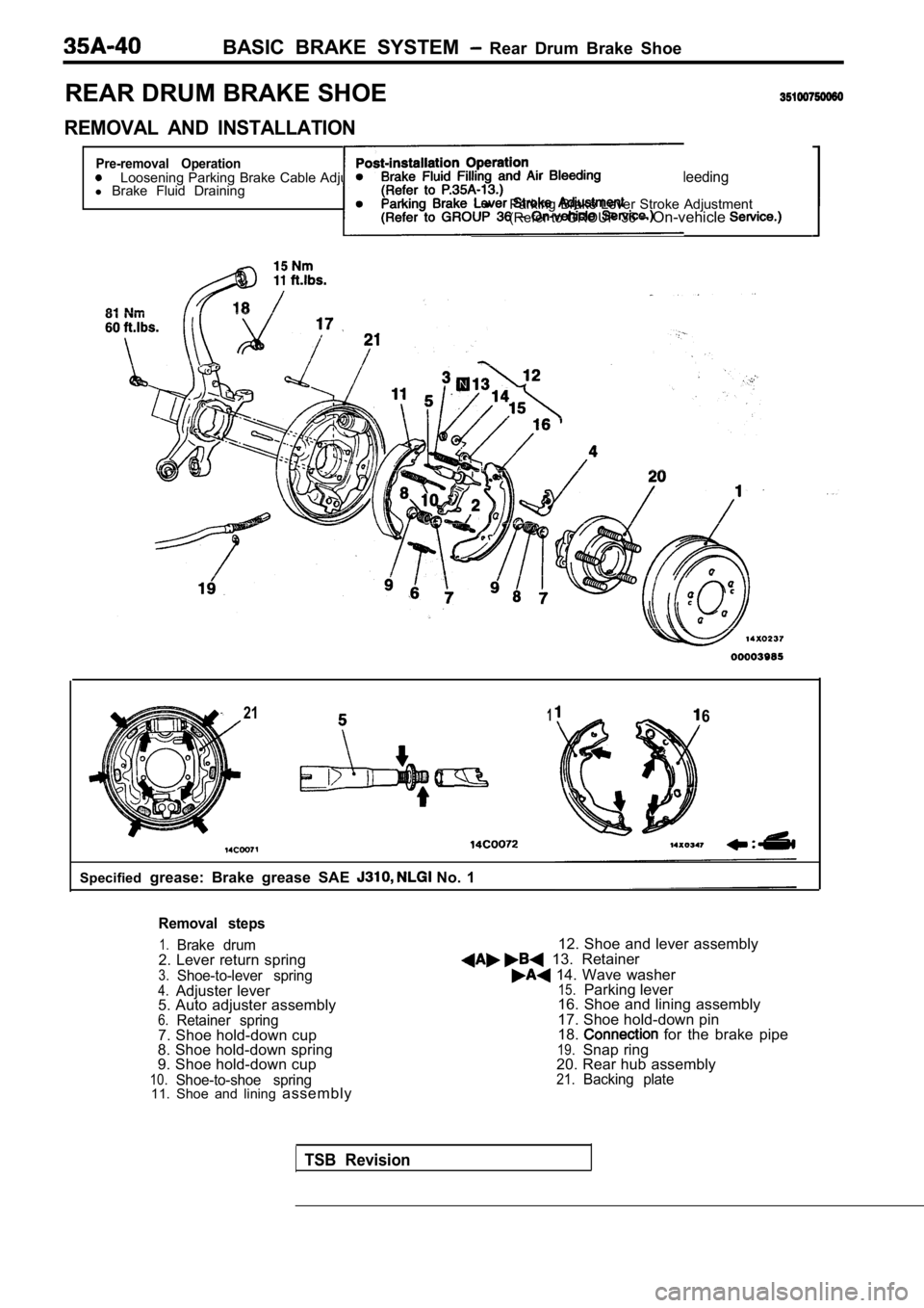
BASIC BRAKE SYSTEM Rear Drum Brake Shoe
REAR DRUM BRAKE SHOE
REMOVAL AND INSTALLATION
Pre-removal OperationLoosening Parking Brake Cable Adjusting Nut. lBrake Fluid Filling and Air Bleedingl
Brake Fluid Drainingl
Parking Brake Lever Stroke Adjustment
(Refer to GROUP 36 On-vehicle
2116
Specified grease: Brake grease SAE No. 1
Removal steps
1.Brake drum2. Lever return spring3.Shoe-to-lever spring4.Adjuster lever
5. Auto adjuster assembly
6.Retainer spring7. Shoe hold-down cup
8. Shoe hold-down spring
9. Shoe hold-down cup
10.Shoe-to-shoe spring11. Shoe and lining assembly 12. Shoe and lever assembly
13. Retainer
14. Wave washer15.Parking lever
16. Shoe and lining assembly
17. Shoe hold-down pin
18.
for the brake pipe19.Snap ring
20. Rear hub assembly
21.Backing plate
TSB Revision
Page 1679 of 2103
BASIC BRAKE SYSTEM Rear Brake
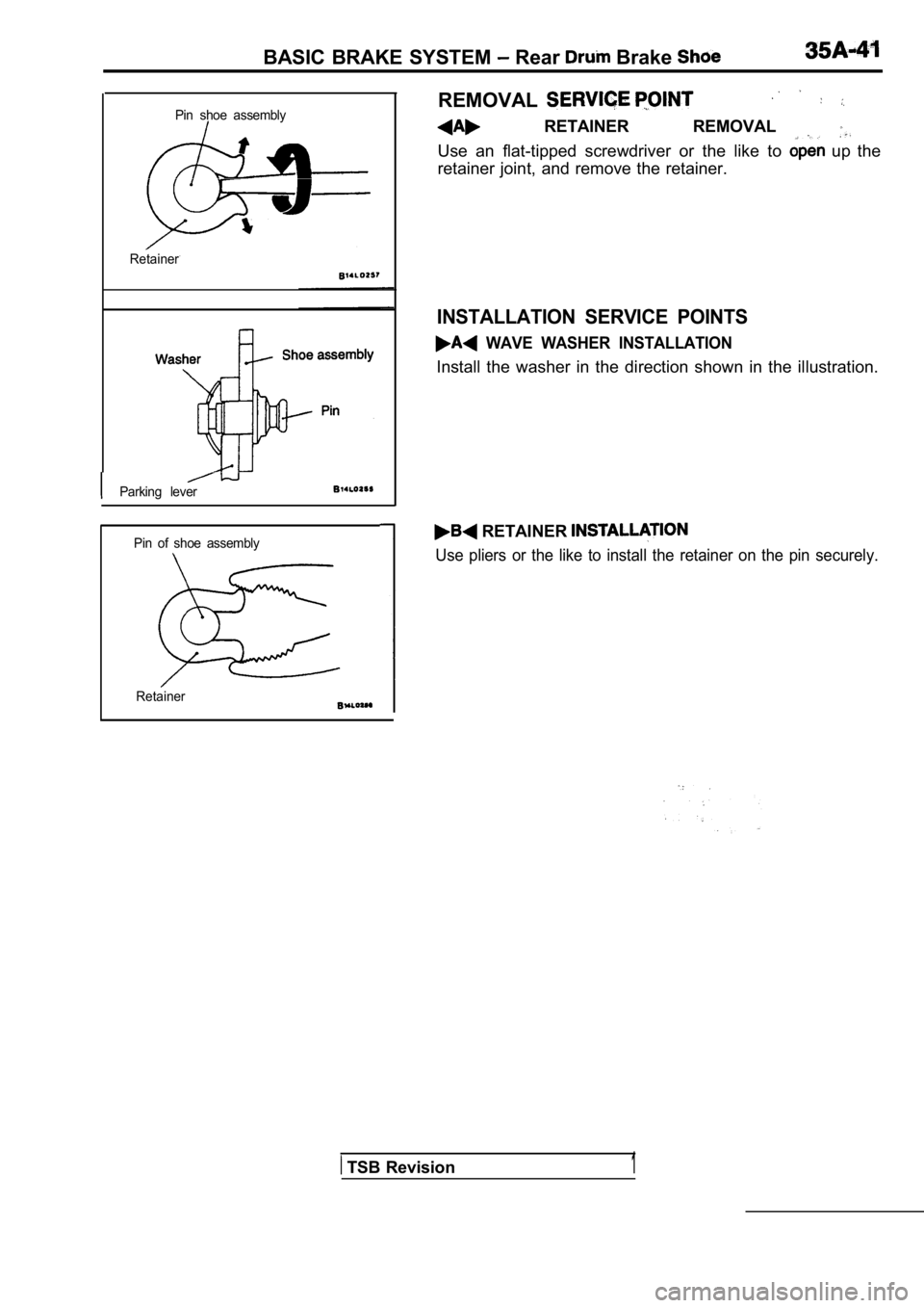
REMOVALPin shoe assembly RETAINER REMOVAL
Use an flat-tipped screwdriver or the like to up the
retainer joint, and remove the retainer.
Retainer
INSTALLATION SERVICE POINTS
WAVE WASHER INSTALLATION
Install the washer in the direction shown in the il lustration.
Parking lever
Pin of shoe assembly
Retainer
RETAINER
Use pliers or the like to install the retainer on t he pin securely.
TSB Revision1
Page 1683 of 2103
BASIC BRAKE SYSTEM Rear Disc Brake
REAR DISC BRAKE
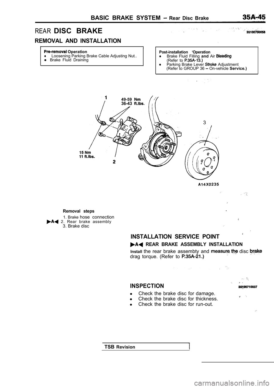
REMOVAL AND INSTALLATION
I
I OperationlLoosening Parking Brake Cable Adjusting Nut..
l Brake Fluid DrainingPost-installation ‘OperationlBrake Fluid Filling andAir(Refer to lParking Brake Lever Adjustment
(Refer to GROUP 36 On-vehicle Service.)
49-59
36-43
3
Removal steps
1. Brake hose connection 2. Rear brake assembly
3. Brake disc .
INSTALLATION SERVICE POINT
REAR BRAKE ASSEMBLY INSTALLATION
Install
the rear brake assembty and disc
drag torque. (Refer to
INSPECTION
lCheck the brake disc for damage.
l Check the brake disc for thickness.
l Check the brake disc for run-out.
TSB Revision