MITSUBISHI TRITON 1997 Workshop Manual
Manufacturer: MITSUBISHI, Model Year: 1997, Model line: TRITON, Model: MITSUBISHI TRITON 1997Pages: 1310, PDF Size: 22.38 MB
Page 991 of 1310

11
INSPECTION PROCEDURE FOR TROUBLE SYMPTOMS
INSPECTION PROCEDURE 1
None of the doors can be locked or unlocked using
the transmitter.Probable cause
The cause may be a malfunction of the transmitter or ETACS-
ECU, defective connection between ETACS-ECU and junction
block, defective power supply voltage to ETACS-ECU input
line due to commercial equipment, or the lock and unlock sig-
nals are not being sent to the ETACS-ECU.•
Malfunction of transmitter
•
Malfunction of ETACS-ECU
•
Malfunction of key reminder switch
•
Malfunction of wiring harness or connector
•
Malfunction of door switch
•
Defective connection between ETACS-ECU and
junction block
•
Defective power supply voltage to ETACS-ECU
input line due to commercial equipment
Check the central door lock systemCan the doors be locked and unlocked by the pas-
senger’s-side door key cylinder and lock knob?
YesNo
Has the encrypted code been registered properly? * NG Re-register the encrypted code. (Refer to P.42.6)
OK
Replace the transmitter battery. (Refer to P.42-6)
NG
Is a commercial equipment equipped?
NoYes
Remove that equipment, and then check trouble
symptoms.
NG
Check the connection between ETACS-ECU and
junction block claw.NG
Repair
OK
NG .Check the following connectors:
A-56X, C-81, C-91
OK NG
Measure at the ETACS-ECU connector C-91.
•
Disconnect the connector, and measure at the
harness side.
•
Voltage between 2 and body earth
OK:
System voltageCheck trouble symptomsRepair
OK NG
Check the harness wire, and repair if necessary.
•
Between fusible link No.5 and ETACS-ECU
Door switch continuity check
OK NG
Mut-II Pulse Check
•
Door switch input signal
OK:
MUT-II Buzzer sounds once when opening
and closing each door.NG
Repair
OK
Check the following connectors:
C-110, D-03, D-07, D-14, D-17, D-21
OK NG
Check trouble Symptoms.Repair
NG
To next pageCheck the harness wire, and repair if necessary.
•
Between ETACS-ECU and door switch
NOTE
*: This should be done if a transmitter, receiver or ETACS-ECU has been replaced, and if a secret cod
has not been registered properly
BODY – Keyless Entry System42-3
Page 992 of 1310

12From previous page
Key reminder switch continuity check
OK NG
MUT-II Pulse Check
•
Key reminder switch input signal
OK:
MUT-II buzzer sounds once when removing
and inserting ignition key.NG
Repair
OK
Check the following connectors:
C-72, C-79, C-86, C-91
Replace the transmitter.OK NG
OK
Check trouble symptomsRepair
Check the trouble symptoms.NG
OK
Replace the ETACS-ECU.
Check the harness wire, and repair if necessary.
•
Between key reminder switch and ETACS-ECU
•
Between key reminder switch and earth
INSPECTION PROCEDURE 2
All of the doors can be locked and unlocked using th
transmitter, but the room lamp or turn-signal lamp does
not flash or illuminate. (However, the room lamp oper-
ates normally when the doors are opened and closed.)Probable cause
If neither room lamp nor turn-signal lamp flash/illuminate, the
cause may be a malfunction of the ETACS-ECU or driver’s-side
door lock actuator.
If either room lamp or turn-signal lamp does not flash/illuminate,
the cause may be a malfunction of the room lamp circuit or turn-
signal lamp.•
Malfunction of ETACS-ECU
•
Malfunction of driver’s door lock actuator
•
Burnt turn-signal lamp bulb
•
Malfunction of connector or wiring harness
Carry out the troubleshooting for room lamp circuit.Does the room lamp go on/go off simultaneous
with opening/closing door?NO
Yes
Does the turn-signal lamp flash when the turn-
signal lamp switch is operated?NO
Carry out the troubleshooting for turn-signal lamp
circuit.
Yes
NG
Check the driver’s door lock actuator
OK NG
MUT-II Pulse Check
•
Drivers door lock actuator switch input signal
OK:
MUT-II buzzer sounds once when locking
or unlocking driver’s door.Replace
OKCheck the following connectors:
C-38, C-110, E-09
E-20
Replace the ETACS-ECUOK NG
Check trouble symptoms.Repair
NG
Check the harness wire, and repair if necessary.
•
Between ETACS-ECU and driver’s door lock actua-
tor
•
Between driver’s door lock actuator and earth
42-4BODY – Keyless Entry System
Page 993 of 1310

13
INSPECTION PROCEDURE 3
Encrypted codes cannot be registered Probable cause
The cause may be a malfunction of the diagnosis con-
nector, ETACS-ECU or diagnosis output circuit.•
Malfunction of MUT-II
•
Malfunction of connector or wiring harness
•
Malfunction of ETACS-ECU
NGCheck the following connectors:
C-35, D-110
OK NG
Check trouble symptomsRepair
NG
Measure at diagnosis connector C-35 and ETACS-
ECU connector D-110.
•
Disconnect the connector, and measure at har
ness side.
•
Continuity between following terminals:
OK:
Continuity
28
•
Between the ETACS-ECU and diagnosis connector
OK
Can the MUT-II communicate with other systems?
Yes No
NGCheck the following connectors:
A-56X, C-35, C-79, C-81
OK NG
Check trouble symptoms.Repair
Measure at the diagnosis
connector C-35
•
Voltage between 16
and body earth
OK:
System voltage
NG
OKCheck the harness wire, and repair if necessary.
•
Between fusible link No.5 and diagnosis connector
OK
Replace MUT-II.Measure at the diagnosis
connector C-35.
•
Continuity between 4
and body earth
•
Continuity between 5
and body earth
OK:
System voltage
NG
NG
RepairCheck the following
connectors:
C-35, C-86
OK
Check trouble symptoms.NG
Check the harness wire, and repair if necessary.
•
Between the diagnosis connector and earth
NG
Check the following connectors:
A-56X, C-81, C-82, C-88, C-91
OK NG
Check trouble symptomsRepair
NG
Measure at the ETACS-ECU connector C-91.
•
Disconnect the connector, and measure at the
harness side
•
Voltage between 1 and body earth
•
Voltage between 2 and body earth
•
Voltage between 3 and body earth
OK:
System voltage
OKCheck the harness wire, and repair if necessary.
•
Between dedicated fuse No.6 and ETACS-ECU
•
Between ignition switch (IG1) and ETACS-ECU
Check the following connectors:
C-86, C-91
OK NG
Check trouble symptoms.
Repair
Measure at the ETACS-ECU connectors C-91
•
Disconnect the connector, and measure at the
harness side.
•
Between 10 for connector C-91 and body earth
OK:
System voltage
NG
OK
Replace the ETACS-ECU.Check the harness wire, and repair if necessary.
•
Between the ETACS-ECU and earth
BODY – Keyless Entry System42-5
Page 994 of 1310
Page 995 of 1310
Page 996 of 1310
Page 997 of 1310

Page 998 of 1310

18
NOTES
Page 999 of 1310
Page 1000 of 1310
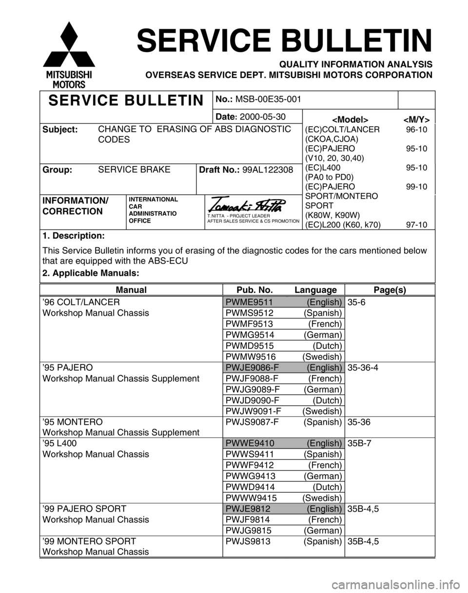
O
VER SEA S S ER VIC E D EPT. M IT S U B IS H I M OTO RS C O RPO RATIO N C
O DES C
O RREC TIO N C
AR A
D M IN IS TR A TIO O
FF IC E A
FTE R S ALE S S E R VIC E & C S P R O M OTIO N (
C KO A,C JO A) (
E C )P AJE R O (
V 10 , 2 0, 3 0 ,4 0 ) (
E C )L 400 (
P A0 t o P D 0) (
E C )P AJE R O S
P O RT/M ONTE R O S
P O RT (
K 80 W , K 90W ) (
E C )L 200 ( K 60, k 7 0) 9
5-1 0 9
5-1 0 9
9-1 0 9
7-1 0 t
h at a re e q uip pe d w it h t h e A BS-E C U M
an ual Pub. N o. Lan guag e Pag e(s ) P
W ME9511 (
E nglis h ) 35-6 W
ork sh op M anua l C hassis PW MS9512 (S panis h ) P
W MF9513 (F re nch ) P
W MG9514 (G erm an) P
W MD9515 (D utc h ) P
W MW 9516 (S w edis h ) ’
9 5 P A JE R O P
W JE 908 6-F (
E nglis h ) 3
5-3 6 -4 W
ork sh op M anua l C hassis S upple m ent PW JF 9088-F (F re nch ) P
W JG 908 9-F (G erm an) P
W JD 9090-F (D utc h ) P
W JW 9091-F (S w edis h ) ’
9 5 M ONTE R O W
ork sh op M anua l C hassis S upple m ent P
W JS 908 7-F (S panis h ) 35-3 6 ’
9 5 L 4 00 P
W WE9410 (
E ng lis h ) 35B -7 W
ork sh op M anua l C hassis PW WS9411 (S panis h ) P
W WF9412 (F re nch ) P
W WG9413 (G erm an) P
W WD9414 (D utc h ) P
W WW9415 (S w edis h ) ’
9 9 P A JE R O S PO RT P
W JE 981 2 (
E ng lis h ) 35B -4 ,5 W
ork sh op M anua l C hassis PW JF 9814 (F re nch ) P
W JG 981 5 (G erm an) ’
9 9 M ONTE R O S PO RT W
ork sh op M anua l C hassis P
W JS 981 3 (S panis h ) 35B -4 ,5