engine oil NISSAN 300ZX 1984 Z31 Steering System Workshop Manual
[x] Cancel search | Manufacturer: NISSAN, Model Year: 1984, Model line: 300ZX, Model: NISSAN 300ZX 1984 Z31Pages: 20, PDF Size: 0.7 MB
Page 6 of 20

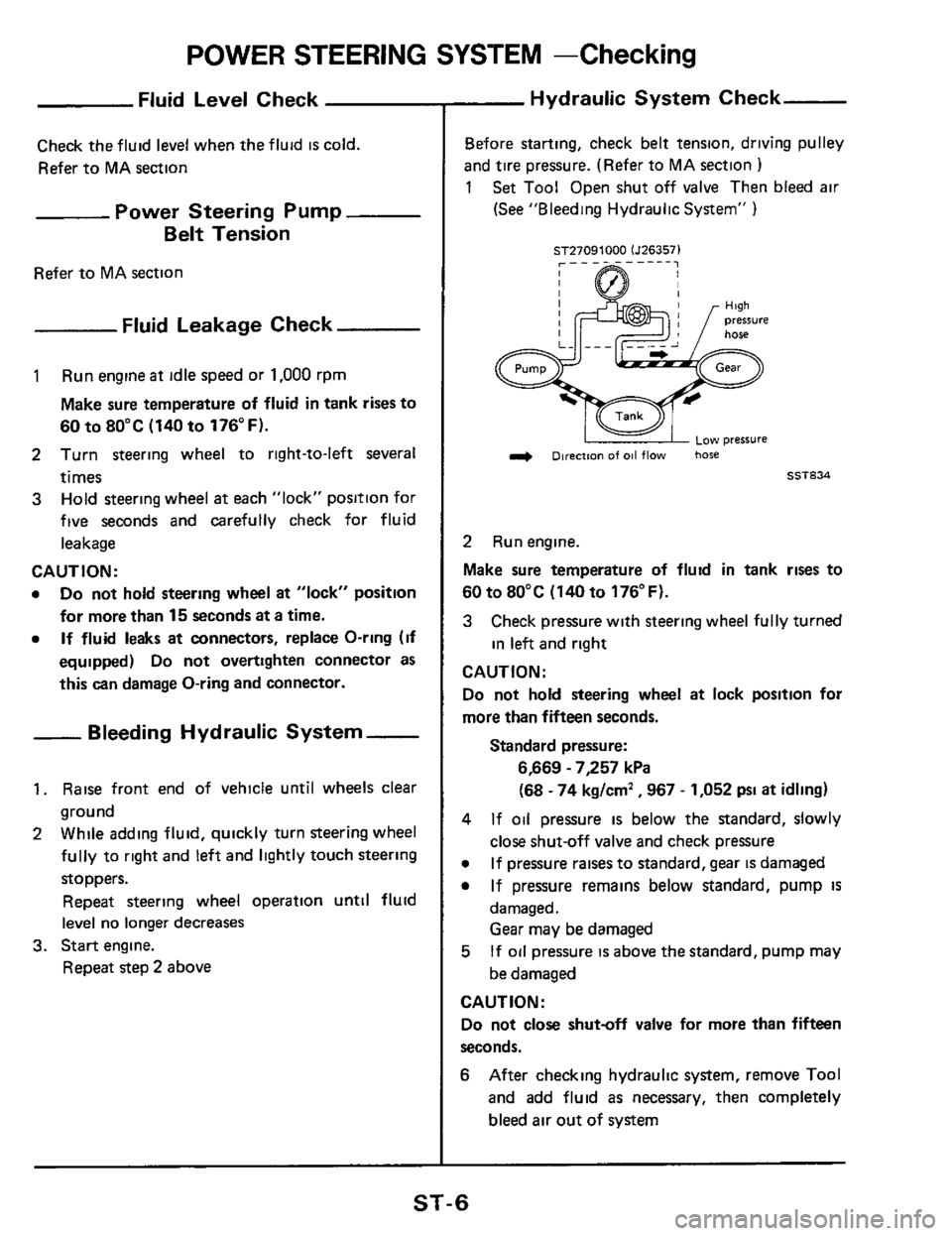
POWER STEERING SYSTEM -Checking
Fluid Level Check
Check the fluid level when the fluid IS cold.
Refer to MA section
Power Steering Pump
Belt Tension
Refer to MA section
Fluid Leakage Check
1 Run engine at idle speed or 1,000 rpm
Make sure temperature of fluid
in tank rises to
60 to 80°C (140 to 176°F).
2 Turn steering wheel to right-to-left several
times
3 Hold steering wheel at each "lock" position for
five seconds
and carefully check for fluid
leakage
CAUTION :
0 Do not hold steering wheel at "lock" position
for more than 15 seconds at a time.
0 If fluid leaks at connectors, replace O-ring (if
equipped) Do not overtighten connector as
this can damage O-ring and connector.
- Bleeding Hydraulic System -
1. Raise front end of vehicle until wheels clear
ground
2 While adding fluid, quickly turn steering wheel
fully to right and
left and lightly touch steering
stoppers.
Repeat steering wheel operation until fluid
level no
longer decreases
Repeat step 2 above
3. Start engine.
Hydraulic System Check
Before starting, check belt tension, driving pulley
and tire pressure. (Refer to MA section )
1 Set Tool Open shut off valve Then bled air
(See "Bleeding Hydraulic System" )
ST27091000 lJ263571
L 1 ow pressure
& Direction of 011 flow hose
ET834
2 Run engine.
Make sure temperature of fluid in tank rises to
60 to 80°C
(140 to 176°F).
3 Check pressure with steering wheel fully turned
in left and right
CAUTION:
Do not hold steering wheel at lock position for
more than fifteen seconds.
Standard pressure:
6,669 - 7,257 kPa
(68
- 74 kglcm' ,967 - 1,052 psi at idling)
4
0
0
If oil pressure is below the standard, slowly
close shut-off valve and check pressure
If pressure raises to standard, gear is damaged
If pressure remains below standard, pump
IS
damaged.
Gear may be damaged
If oil pressure is above the standard, pump may
be damaged 5
CAUTION:
Do not close shutoff valve for more than fifteen
seconds.
6 After checking hydraulic system, remove Tool
and add fluid as necessary, then completely
bleed
air out of system
ST-6
Page 16 of 20

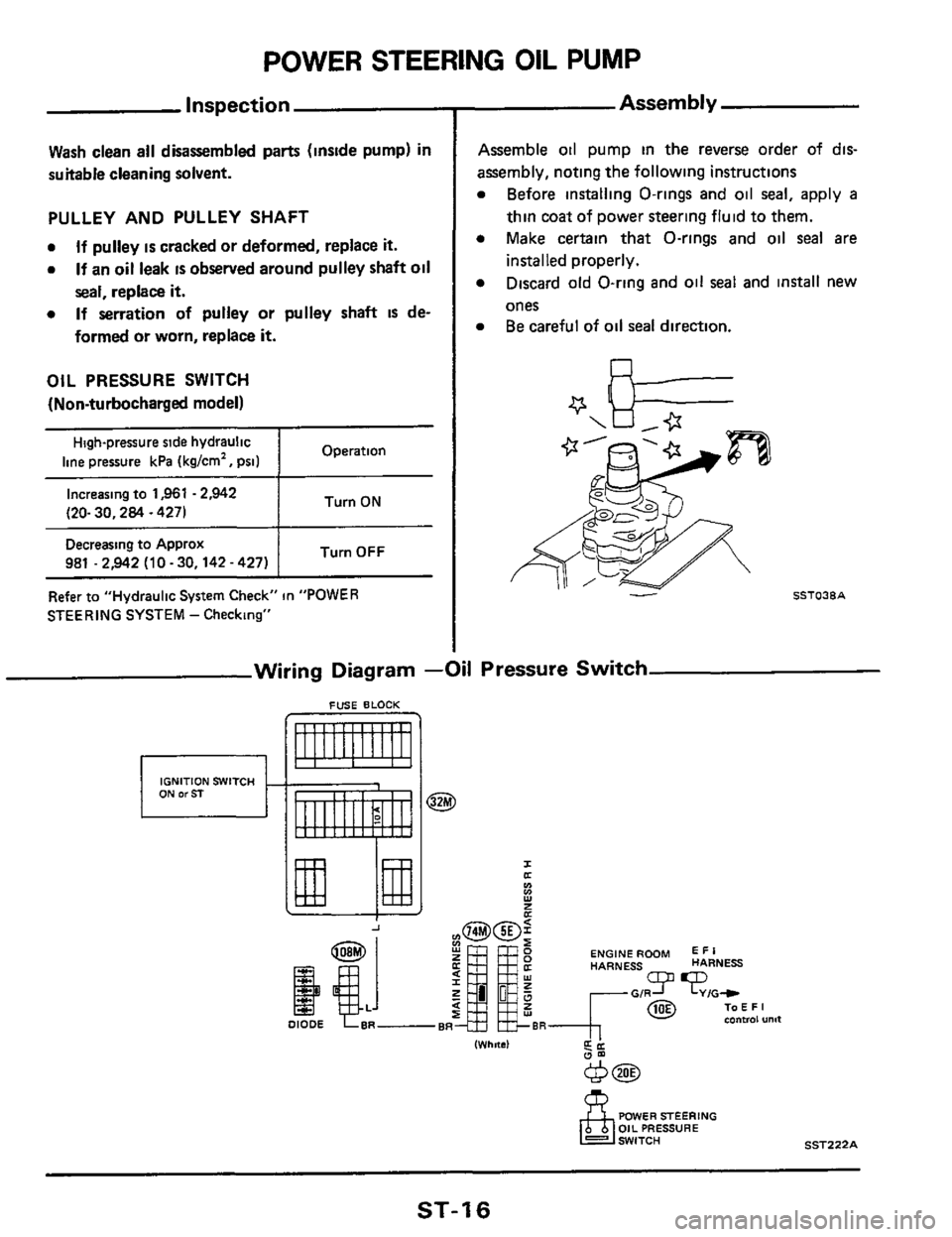
POWER STEERlNG OIL PUMP
Inspection
Wash clean all disassembled parts (inside pump) in
suitable cleaning solvent.
PULLEY AND PULLEY SHAFT
0
0
If pulley is cracked or deformed, replace it.
If an oil leak IS observed around pulley shaft oil
seal, replace it.
If serration of pulley or pulley shaft IS de-
formed
or worn, replace it.
0
OIL PRESSURE SWITCH
(Non-turbocharged model)
Operation High-pressure side hydraulic
line pressure kPa (kglcm', psi) ~~
I Turn ON Increasing to 1,961 - 2,942
(20- 30,284 ~ 4271
Turn OFF Decreasing to Approx
981 .2,942 (10 - 30,142 - 427)
Refer to "Hydraulic
System Check" in "POWER
STEERING SYSTEM
- Checking"
Assembly
Assemble 011 pump in the reverse order of dts-
assembly, noting the following instructions
Before installing O-rings and oil seal, apply a
thin coat of power steering fluid to them.
Make certain that O-rings and oil
seal are
installed properly.
Discard old O-ring and oil
seal and install new
ones Be careful of
oil seal direction.
Wiring Diagram -Oil Pressure Switch
FUSE BLOCK
IGNITION SWITCH
I a
Y
Ln v)
E
ENGINE ROOM E I R HARNESS HARNESS
IWhnsl d'
POWER STEERING OIL PRESSURE
SST222A
ST-1 6
Page 18 of 20

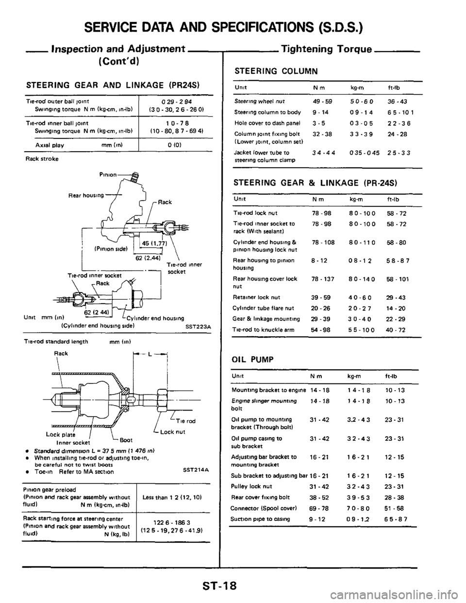
SERVICE DATA AND SPECIFICATIONS (S.D.S.)
Tie-rod outer ball joint
Swinging torque N m (kgim. m4b)
- Inspection and Adjustment
(Cont'd)
0 29.2 94
I3 0.30,2 6.26
01 ~~~
Pinion gear
preload
(Ptnlon and rack gear assembly without
fluid1 N m Ikgcm, tn-lbl
Tie-rod inner ball joint 10-78 Swinging torque N m (kgem, in-lb) 110 - 80.8 7 .69 41
__~ ~
Less than 1 2 (12.10)
Axial Dlay mm (in) I 0 IO)
Rack stroke
Pinion
I' ? Pack
Rear housing
Tne-rod innel rocket Tie-rod inner socket
& .l
Unit mm Ion) linder end housina - ICyImder end hourmg sadel SST223A
Tie-rod standard length mm (In)
Inner rocket
8 Standard dimensnn L = 37 5 mm I1 476 ln) e When installing tie-rod or adjusting toe-in, be careful not Io twist boots Toe-in Refer to MA seCtion SST214A
1226- 1863
(12 5.19.276 -41.9) Rack stanmg force at steering center (Pinion and rack gear assembly without
fluid) N (kg. Ib)
Tightening Torque
STEERING COLUMN ~~~~
U"lt Nm kg-m ft-lb
Steering wheel nut 49-59 50-60 36-43
Steering column to
body 9 - 14 09-14 65-101
Hole cover to dash panel 3 .5 03-05 22-36
Columnlaintfixingbolt 32-38 33-39 24.28 (Lower joint, column set)
Jacket lower tube to
34-44 035-045 25-33 steering column clamp
STEERING GEAR & LINKAGE (PR-24s)
Unit Nm kg-m ft-lb
Tie-rod lock nut
Tie-rod inner socket to
rack (With sealant)
Cylinder end housmg
& pinion housmg lock nut
Rear housmg to pman
housing
Rear housing
cover lack
nut
Retainer lock nut
Cylinder tube flare nut
Gear & linkage mounting
Tie-rod
to knuckle arm
78 -98
78 -98
78 - 108
8-12
78.137
39 - 59
20
- 26
29-39
54 -98
80-100
80.100
80.110
08-1 2
80-140
40-60
20-27
30-40
55-100
58.72
58-72
58-80
58-87
Ea - 101
29 -43
14-20
22-29
40 - 72
OIL PUMP
U"lt Nm kg-m ft-lb
Mounting bracket to engine 14. 18
Engine sllnger mounting 14 - 18 bolt
011 pump to mounting 31 .42 bracket (Through bolt)
011 pump casing to 31 -42 rub bracket
Adlusting bar bracket
to 16.21 mounting bracket
Sub bracket to adjusting bar
16 - 21
Pulley lock nut 31 -42
Rear cover fixing bolt 38 - 52
Connector (Spool cover) 69 - 78
Suction piDe to easing 9-12
14-1 8
14-18
33-43
32-43
16-21
16-21
32-43
39-53
70-80
09-12
10-13
10
- 13
23 - 31
23 - 31
12-15
12-15
23.31
28-38
51
-58
65-87
ST-1 8