clock NISSAN 370Z 2020 Owner´s Manual
[x] Cancel search | Manufacturer: NISSAN, Model Year: 2020, Model line: 370Z, Model: NISSAN 370Z 2020Pages: 455, PDF Size: 2.22 MB
Page 201 of 455
2. Turn the temperature control dial toset the desired temperature.
. The temperature of the passenger
compartment will be maintained
automatically. Air flow distribution
and fan speed are also controlled
automatically.
A visible mist may be seen coming from
the ventilators in hot, humid conditions as
the air is cooled rapidly. This does not
indicate a malfunction.
Dehumidified defrosting or defogging:
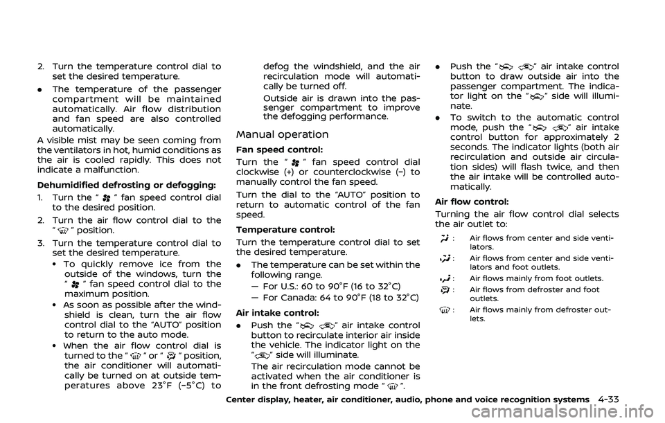
1. Turn the “
” fan speed control dial
to the desired position.
2. Turn the air flow control dial to the “
” position.
3. Turn the temperature control dial to set the desired temperature.
.To quickly remove ice from theoutside of the windows, turn the
“
” fan speed control dial to the
maximum position.
.As soon as possible after the wind- shield is clean, turn the air flow
control dial to the “AUTO” position
to return to the auto mode.
.When the air flow control dial isturned to the “”or“” position,
the air conditioner will automati-
cally be turned on at outside tem-
peratures above 23°F (−5°C) to defog the windshield, and the air
recirculation mode will automati-
cally be turned off.
Outside air is drawn into the pas-
senger compartment to improve
the defogging performance.
Manual operation
Fan speed control:
Turn the “
” fan speed control dial
clockwise (+) or counterclockwise (−) to
manually control the fan speed.
Turn the dial to the “AUTO” position to
return to automatic control of the fan
speed.
Temperature control:
Turn the temperature control dial to set
the desired temperature.
. The temperature can be set within the
following range.
— For U.S.: 60 to 90°F (16 to 32°C)
— For Canada: 64 to 90°F (18 to 32°C)
Air intake control:
. Push the “
” air intake control
button to recirculate interior air inside
the vehicle. The indicator light on the
“
” side will illuminate.
The air recirculation mode cannot be
activated when the air conditioner is
in the front defrosting mode “
”. .
Push the “
” air intake control
button to draw outside air into the
passenger compartment. The indica-
tor light on the “
” side will illumi-
nate.
. To switch to the automatic control
mode, push the “
” air intake
control button for approximately 2
seconds. The indicator lights (both air
recirculation and outside air circula-
tion sides) will flash twice, and then
the air intake will be controlled auto-
matically.
Air flow control:
Turning the air flow control dial selects
the air outlet to:
: Air flows from center and side venti- lators.
: Air flows from center and side venti-lators and foot outlets.
: Air flows mainly from foot outlets.
: Air flows from defroster and footoutlets.
: Air flows mainly from defroster out-lets.
Center display, heater, air conditioner, audio, phone and voice recognition systems4-33
Page 217 of 455
JVH0923X
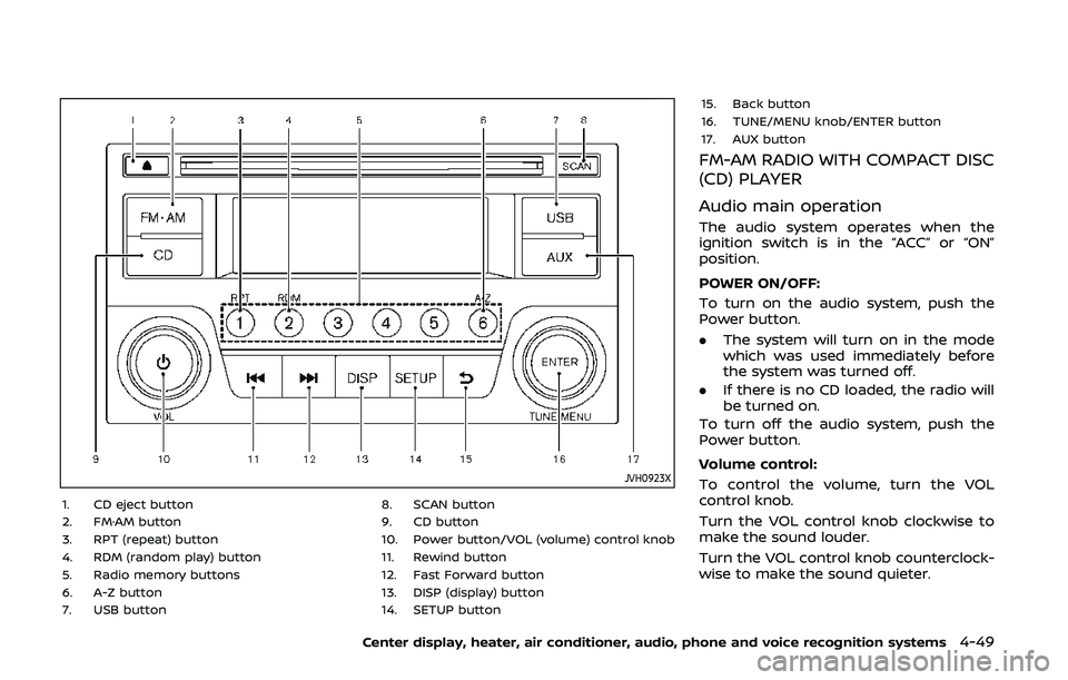
1. CD eject button
2. FM·AM button
3. RPT (repeat) button
4. RDM (random play) button
5. Radio memory buttons
6. A-Z button
7. USB button8. SCAN button
9. CD button
10. Power button/VOL (volume) control knob
11. Rewind button
12. Fast Forward button
13. DISP (display) button
14. SETUP button15. Back button
16. TUNE/MENU knob/ENTER button
17. AUX button
FM-AM RADIO WITH COMPACT DISC
(CD) PLAYER
Audio main operation
The audio system operates when the
ignition switch is in the “ACC” or “ON”
position.
POWER ON/OFF:
To turn on the audio system, push the
Power button.
.
The system will turn on in the mode
which was used immediately before
the system was turned off.
. If there is no CD loaded, the radio will
be turned on.
To turn off the audio system, push the
Power button.
Volume control:
To control the volume, turn the VOL
control knob.
Turn the VOL control knob clockwise to
make the sound louder.
Turn the VOL control knob counterclock-
wise to make the sound quieter.
Center display, heater, air conditioner, audio, phone and voice recognition systems4-49
Page 218 of 455
4-50Center display, heater, air conditioner, audio, phone and voice recognition systems
SETUP button:
To configure Audio, Clock, Language or
Scroll direction settings, perform the
following procedure:
1. Push the SETUP button.
2. Push the ENTER button.
3. Turn the TUNE/MENU knob clockwiseor counterclockwise, the display will
appear in the following order:
Audio �œClock �œLanguage �œScroll
Direction
After the desired levels have been set,
push either the back button repeatedly,
the SETUP button, or wait for 8 seconds
without pushing any buttons to exit the
menu screen.
Audio adjustments:
Push the SETUP button to enter the setup
menu screen then select Audio by using
TUNE/MENU knob.
Each time the ENTER button is pushed,
the mode will change as follows:
Bass ?Treble ?Fade ?Balance ?AUX
VOL ?SPD VOL ?Audio (setup menu
screen)
Turn the TUNE/MENU knob clockwise or
counterclockwise to adjust the following
items and push the ENTER button to
confirm. Bass control:
Use this control to enhance or attenuate
bass response sound.
Treble control:
Use this control to enhance or attenuate
the treble.
Fade control:
Use this control to adjust the balance of
the volume between the front and rear (if
so equipped) speakers.
Balance control:
Use this control to adjust the balance of
the volume between the left and right
speakers.
AUX VOL (Auxiliary volume) control:
Use this control to adjust the volume
output from the auxiliary source.
SPD VOL (Speed volume) control:
This mode controls the volume output
from the speakers automatically in rela-
tion to vehicle speed.
Adjusting the setting to 0 (zero) turns off
the speed volume feature.
Clock setting:
Push the SETUP button to enter the setup
menu screen then select Clock.
Turn the TUNE/MENU knob, the mode will
change as follows:Set Time
�œON/OFF �œClock Format �œ
Set time
Set Time:
Select Set Time then adjust the clock as
follows:
1. The hour display will start flashing. Turn the TUNE/MENU knob to adjust
the hour and push the ENTER button.
2. The minute display will start flashing. Turn the TUNE/MENU knob to adjust
the minute and push the ENTER
button to finish the clock adjustment.
ON/OFF:
Set the clock display between on or off
when the audio unit is turned off. If set in
the ON position, the clock will be dis-
played when the audio unit is turned off
either by pushing the power button or
when the ignition switch is placed in the
“OFF” position.
Clock Format:
Switch the clock display between 24-hour
mode and 12-hour clock mode.
Language setting:
Push the SETUP button to enter the setup
menu screen then select Language.
Select the appropriate language and
push the ENTER button. Upon completion,
the screen will automatically adapt the
Page 248 of 455
4-80Center display, heater, air conditioner, audio, phone and voice recognition systems
BACK switch (models with
navigation system)
Push this switch to go back to the
previous screen or cancel the selection if
it is not completed.
Volume control switches
Push the upper (+) or lower (−) side switch
to increase or decrease the volume.
Audio source switch
Push the audio source switch to change
the mode to available audio source.
ANTENNA
Window antenna (for Coupe mod-
els)
The antenna pattern is printed inside the
rear window.
CAUTION
. Do not place metalized film near
the rear window glass or attach
any metal parts to it. This may
cause poor reception or noise.
. When cleaning the inside of the
rear window, be careful not to
scratch or damage the rear win-
dow antenna. Lightly wipe along
the antenna with a dampened
soft cloth.
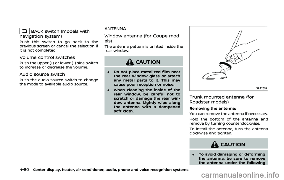
SAA2374
Trunk mounted antenna (for
Roadster models)
Removing the antenna:
You can remove the antenna if necessary.
Hold the bottom of the antenna and
remove by turning counterclockwise.
To install the antenna, turn the antenna
clockwise and tighten.
CAUTION
.To avoid damaging or deforming
the antenna, be sure to remove
the antenna under the following
Page 339 of 455
MCE0001A
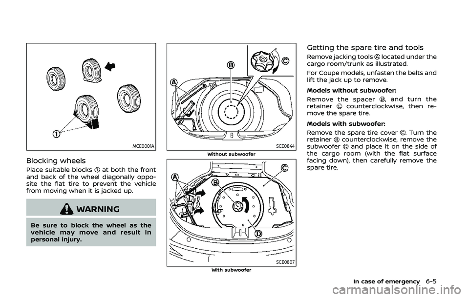
Blocking wheels
Place suitable blocksat both the front
and back of the wheel diagonally oppo-
site the flat tire to prevent the vehicle
from moving when it is jacked up.
WARNING
Be sure to block the wheel as the
vehicle may move and result in
personal injury.
SCE0844Without subwoofer
SCE0807With subwoofer
Getting the spare tire and tools
Remove jacking toolslocated under the
cargo room/trunk as illustrated.
For Coupe models, unfasten the belts and
lift the jack up to remove.
Models without subwoofer:
Remove the spacer
, and turn the
retainercounterclockwise, then re-
move the spare tire.
Models with subwoofer:
Remove the spare tire cover
. Turn the
retainercounterclockwise, remove the
subwooferand place it on the side of
the cargo room (with the flat surface
facing down), then carefully remove the
spare tire.
In case of emergency6-5
Page 341 of 455
SCE0504
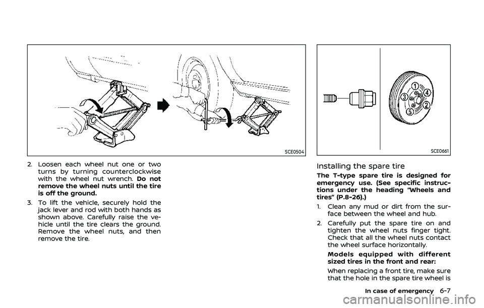
2. Loosen each wheel nut one or twoturns by turning counterclockwise
with the wheel nut wrench. Do not
remove the wheel nuts until the tire
is off the ground.
3. To lift the vehicle, securely hold the jack lever and rod with both hands as
shown above. Carefully raise the ve-
hicle until the tire clears the ground.
Remove the wheel nuts, and then
remove the tire.
SCE0661
Installing the spare tire
The T-type spare tire is designed for
emergency use. (See specific instruc-
tions under the heading “Wheels and
tires” (P.8-26).)
1. Clean any mud or dirt from the sur-face between the wheel and hub.
2. Carefully put the spare tire on and tighten the wheel nuts finger tight.
Check that all the wheel nuts contact
the wheel surface horizontally.
Models equipped with different
sized tires in the front and rear:
When replacing a front tire, make sure
that the hole in the spare tire wheel is
In case of emergency6-7
Page 346 of 455
6-12In case of emergency
SCE0868
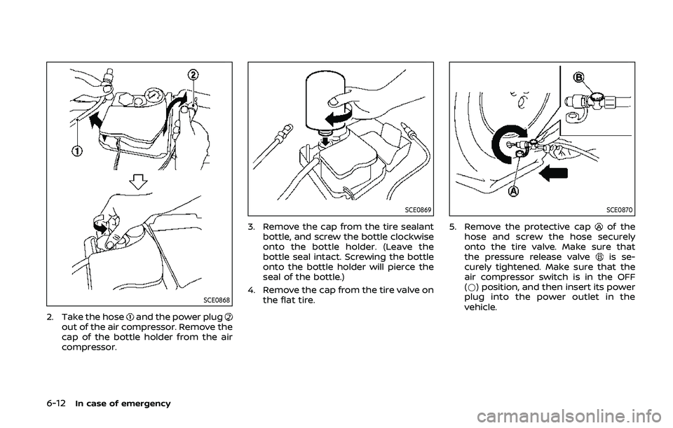
2. Take the hoseand the power plugout of the air compressor. Remove the
cap of the bottle holder from the air
compressor.
SCE0869
3. Remove the cap from the tire sealantbottle, and screw the bottle clockwise
onto the bottle holder. (Leave the
bottle seal intact. Screwing the bottle
onto the bottle holder will pierce the
seal of the bottle.)
4. Remove the cap from the tire valve on the flat tire.
SCE0870
5. Remove the protective capof the
hose and screw the hose securely
onto the tire valve. Make sure that
the pressure release valve
is se-
curely tightened. Make sure that the
air compressor switch is in the OFF
(*) position, and then insert its power
plug into the power outlet in the
vehicle.
Page 375 of 455
SDI2335
Engine oil and filter
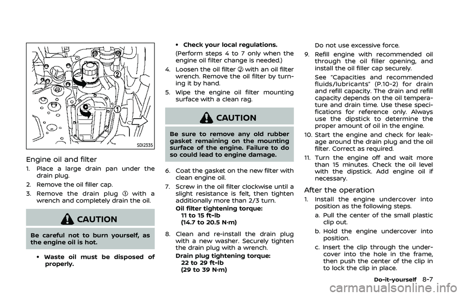
1. Place a large drain pan under thedrain plug.
2. Remove the oil filler cap.
3. Remove the drain plug
with a
wrench and completely drain the oil.
CAUTION
Be careful not to burn yourself, as
the engine oil is hot.
.Waste oil must be disposed of properly.
.Check your local regulations.
(Perform steps 4 to 7 only when the
engine oil filter change is needed.)
4. Loosen the oil filter
with an oil filter
wrench. Remove the oil filter by turn-
ing it by hand.
5. Wipe the engine oil filter mounting surface with a clean rag.
CAUTION
Be sure to remove any old rubber
gasket remaining on the mounting
surface of the engine. Failure to do
so could lead to engine damage.
6. Coat the gasket on the new filter with clean engine oil.
7. Screw in the oil filter clockwise until a slight resistance is felt, then tighten
additionally more than 2/3 turn.
Oil filter tightening torque:11 to 15 ft-lb
(14.7 to 20.5 N·m)
8. Clean and re-install the drain plug with a new washer. Securely tighten
the drain plug with a wrench.
Drain plug tightening torque:22 to 29 ft-lb
(29 to 39 N·m) Do not use excessive force.
9. Refill engine with recommended oil through the oil filler opening, and
install the oil filler cap securely.
See “Capacities and recommended
fluids/lubricants” (P.10-2) for drain
and refill capacity. The drain and refill
capacity depends on the oil tempera-
ture and drain time. Use these speci-
fications for reference only. Always
use the dipstick to determine the
proper amount of oil in the engine.
10. Start the engine and check for leak- age around the drain plug and the oil
filter. Correct as required.
11. Turn the engine off and wait more than 15 minutes. Check the oil level
with the dipstick. Add engine oil if
necessary.
After the operation
1. Install the engine undercover intoposition as the following steps.
a. Pull the center of the small plastic
clip out.
b. Hold the engine undercover into position.
c. Insert the clip through the under- cover into the hole in the frame,
then push the center of the clip in
to lock the clip in place.
Do-it-yourself8-7
Page 448 of 455
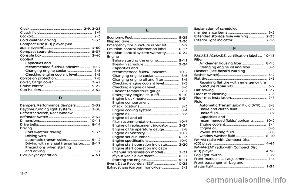
11-2
Clock ........................................................................\
... 2-9, 2-28
Clutch fluid........................................................................\
.... 8-9
Cockpit ........................................................................\
............. 2-3
Cold weather driving ................................................ 5-33
Compact Disc (CD) player (See
audio system) ................................................................. 4-60
Compact spare tire.................................................... 8-37
Console box ..................................................................... 2-46
CoolantCapacities and
recommended fluids/lubricants............... 10-2
Changing engine coolant ................................. 8-5
Checking engine coolant level...................... 8-5
Corrosion protection .................................................... 7-8
Cover, Cargo cover..................................................... 2-47
Cruise control ................................................................. 5-22
Cup holders...................................................................... 2-44
D
Dampers, Performance dampers.................... 5-32
Daytime running light system........................... 2-38
Defroster switch, Rear window
defroster switch ........................................................... 2-34
Dimensions .................................................................... 10-11
Drive belts...................................................................\
....... 8-14
Driving Cold weather driving ......................................... 5-33
Driving with
automatic transmission .................................. 5-12
Driving with manual transmission.......... 5-17
Precautions when starting
and driving.................................................................... 5-2
DVD player operation............................................... 4-61
E
Economy, Fuel................................................................ 5-25
Elapsed time.................................................................... 2-26
Emergency tire puncture repair kit .................. 6-9
Emission control information label............ 10-13
Emission control system warranty ............ 10-24
Engine Before starting the engine............................ 5-11
Break-in schedule ................................................ 5-24
Capacities and
recommended fluids/lubricants............... 10-2
Changing engine coolant ................................. 8-5
Changing engine oil and filter ...................... 8-6
Checking engine coolant level...................... 8-5
Checking engine oil level................................... 8-6
Coolant temperature gauge .......................... 2-7
Emergency engine shut off.......................... 5-10
Engine block heater ........................................... 5-34
Engine compartment
check locations ......................................................... 8-3
Engine cooling system ........................................ 8-4
Engine oil.....................................................................\
... 8-6
Engine oil and oil
filter recommendation ..................................... 10-7
Engine oil replacement indicator ............ 2-24
Engine oil temperature gauge...................... 2-8
Engine oil viscosity .............................................. 10-7
Engine serial number .................................... 10-13
Engine specifications......................................... 10-9
Engine start operation indicator.............. 2-20
Engine start operation indicator
(Manual Transmission models).................. 2-21
If your vehicle overheats ................................ 6-17
Starting the engine............................................. 5-11
Event Data Recorders (EDR)............................. 10-25
Exhaust gas (carbon monoxide) ......................... 5-2 Explanation of scheduled
maintenance items ........................................................ 9-5
Extended storage fuse warning ...................... 2-23
Exterior light indicator............................................. 2-16
F
F.M.V.S.S./C.M.V.S.S. certification label ...... 10-13
Filter
Air cleaner housing filter ................................ 8-15
Changing engine oil and filter ...................... 8-6
Flashers (See hazard warning
flasher switch).................................................................... 6-2
Flat tire........................................................................\
............. 6-3 Repairing flat tire (with emergency tire
puncture repair kit) ................................................ 6-9
Flat towing..................................................................... 10-22
Floor mat cleaning ......................................................... 7-6
Floor mat installation................................................... 7-7
Fluid Automatic Transmission Fluid (ATF) ........ 8-8
Brake and clutch fluid ......................................... 8-9
Brake fluid ..................................................................... 8-9
Capacities and
recommended fluids/lubricants............... 10-2
Engine coolant........................................................... 8-4
Engine oil.....................................................................\
... 8-6
Power steering fluid .............................................. 8-8
Window washer fluid ......................................... 8-10
FM-AM radio with Compact Disc
(CD) player ........................................................................\
. 4-49
FM-AM-SAT radio with Compact Disc
(CD) player ........................................................................\
. 4-58
Fog light switch ............................................................ 2-39
Front manual seat adjustment ............................ 1-4
Front passenger air bag and
status light........................................................................\
1-39