o2 sensor NISSAN ALMERA 2001 Service Manual
[x] Cancel search | Manufacturer: NISSAN, Model Year: 2001, Model line: ALMERA, Model: NISSAN ALMERA 2001Pages: 2898, PDF Size: 60.76 MB
Page 325 of 2898
12. A/T Does Not Perform Lock-up=NJAT0342SYMPTOM:
A/T does not perform lock-up at the specified speed.
1 CHECK SELF-DIAGNOSTIC RESULTS
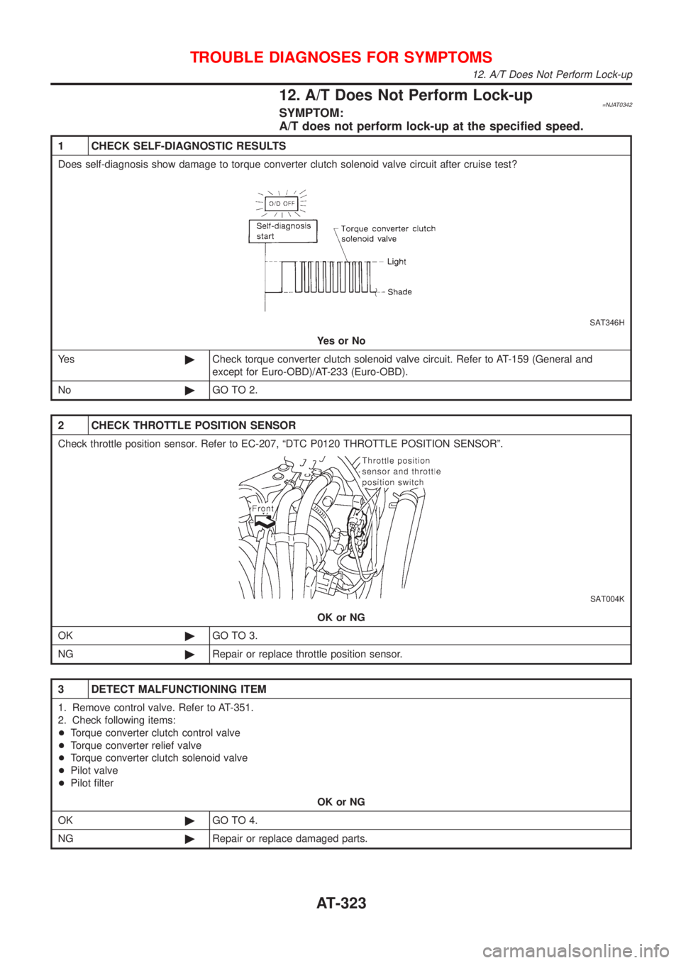
Does self-diagnosis show damage to torque converter clutch solenoid valve circuit after cruise test?
SAT346H
YesorNo
Ye s©Check torque converter clutch solenoid valve circuit. Refer to AT-159 (General and
except for Euro-OBD)/AT-233 (Euro-OBD).
No©GO TO 2.
2 CHECK THROTTLE POSITION SENSOR
Check throttle position sensor. Refer to EC-207, ªDTC P0120 THROTTLE POSITION SENSORº.
SAT004K
OK or NG
OK©GO TO 3.
NG©Repair or replace throttle position sensor.
3 DETECT MALFUNCTIONING ITEM
1. Remove control valve. Refer to AT-351.
2. Check following items:
+Torque converter clutch control valve
+Torque converter relief valve
+Torque converter clutch solenoid valve
+Pilot valve
+Pilot filter
OK or NG
OK©GO TO 4.
NG©Repair or replace damaged parts.
TROUBLE DIAGNOSES FOR SYMPTOMS
12. A/T Does Not Perform Lock-up
AT-323
Page 330 of 2898
15. Engine Speed Does Not Return To Idle
(Light Braking D
4®D3)=NJAT0345SYMPTOM:
+Engine speed does not smoothly return to idle when A/T
shifts from D
4to D3.
+Vehicle does not decelerate by engine brake when turning
overdrive control switch OFF.
+Vehicle does not decelerate by engine brake when shifting
A/T from ªDº to ª2º position.
1 CHECK SELF-DIAGNOSTIC RESULTS
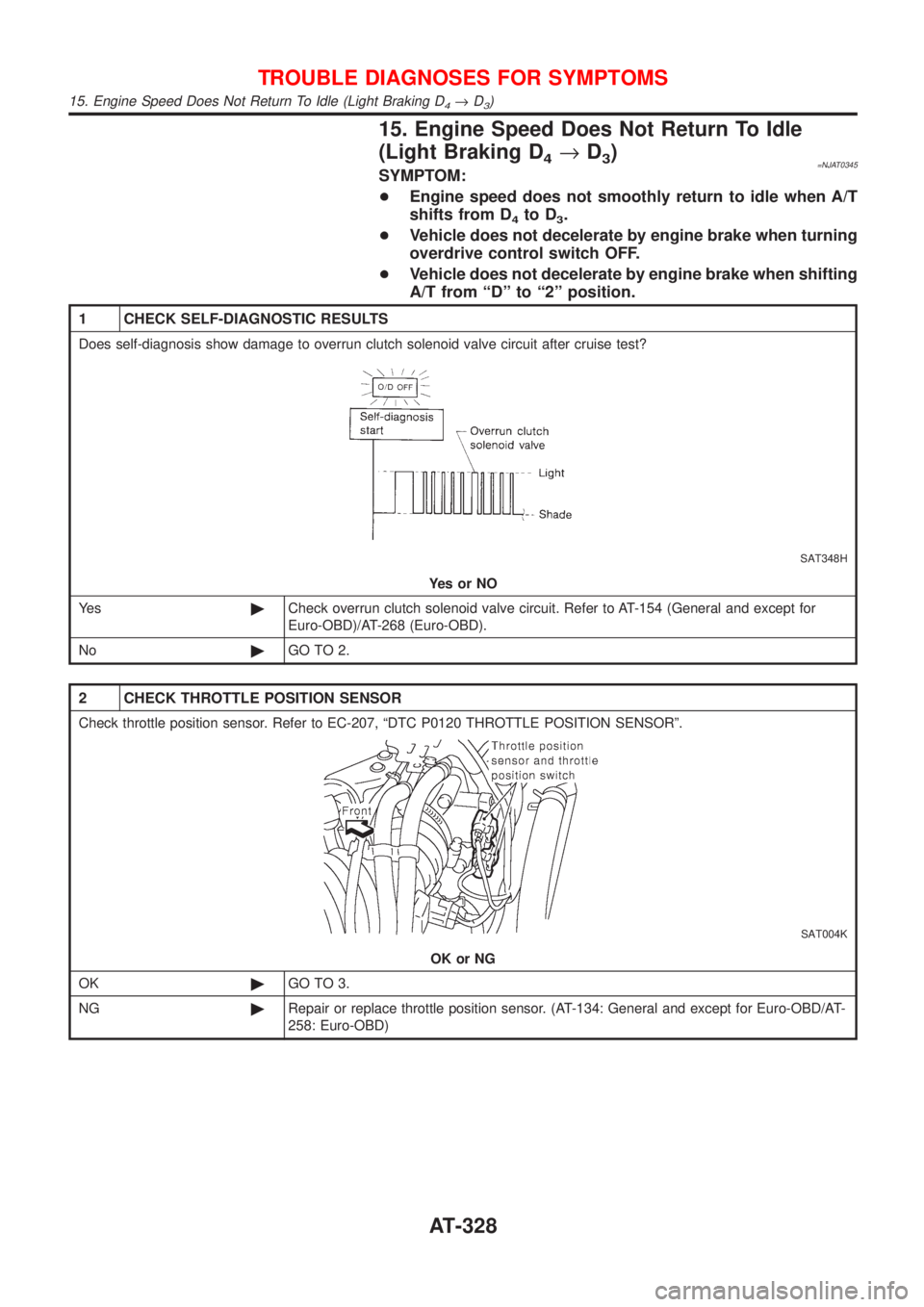
Does self-diagnosis show damage to overrun clutch solenoid valve circuit after cruise test?
SAT348H
YesorNO
Ye s©Check overrun clutch solenoid valve circuit. Refer to AT-154 (General and except for
Euro-OBD)/AT-268 (Euro-OBD).
No©GO TO 2.
2 CHECK THROTTLE POSITION SENSOR
Check throttle position sensor. Refer to EC-207, ªDTC P0120 THROTTLE POSITION SENSORº.
SAT004K
OK or NG
OK©GO TO 3.
NG©Repair or replace throttle position sensor. (AT-134: General and except for Euro-OBD/AT-
258: Euro-OBD)
TROUBLE DIAGNOSES FOR SYMPTOMS
15. Engine Speed Does Not Return To Idle (Light Braking D4®D3)
AT-328
Page 332 of 2898
16. Vehicle Does Not Start From D1NJAT0346SYMPTOM:
Vehicle does not start from D
1on Cruise test Ð Part 2.
1 CHECK SELF-DIAGNOSTIC RESULTS
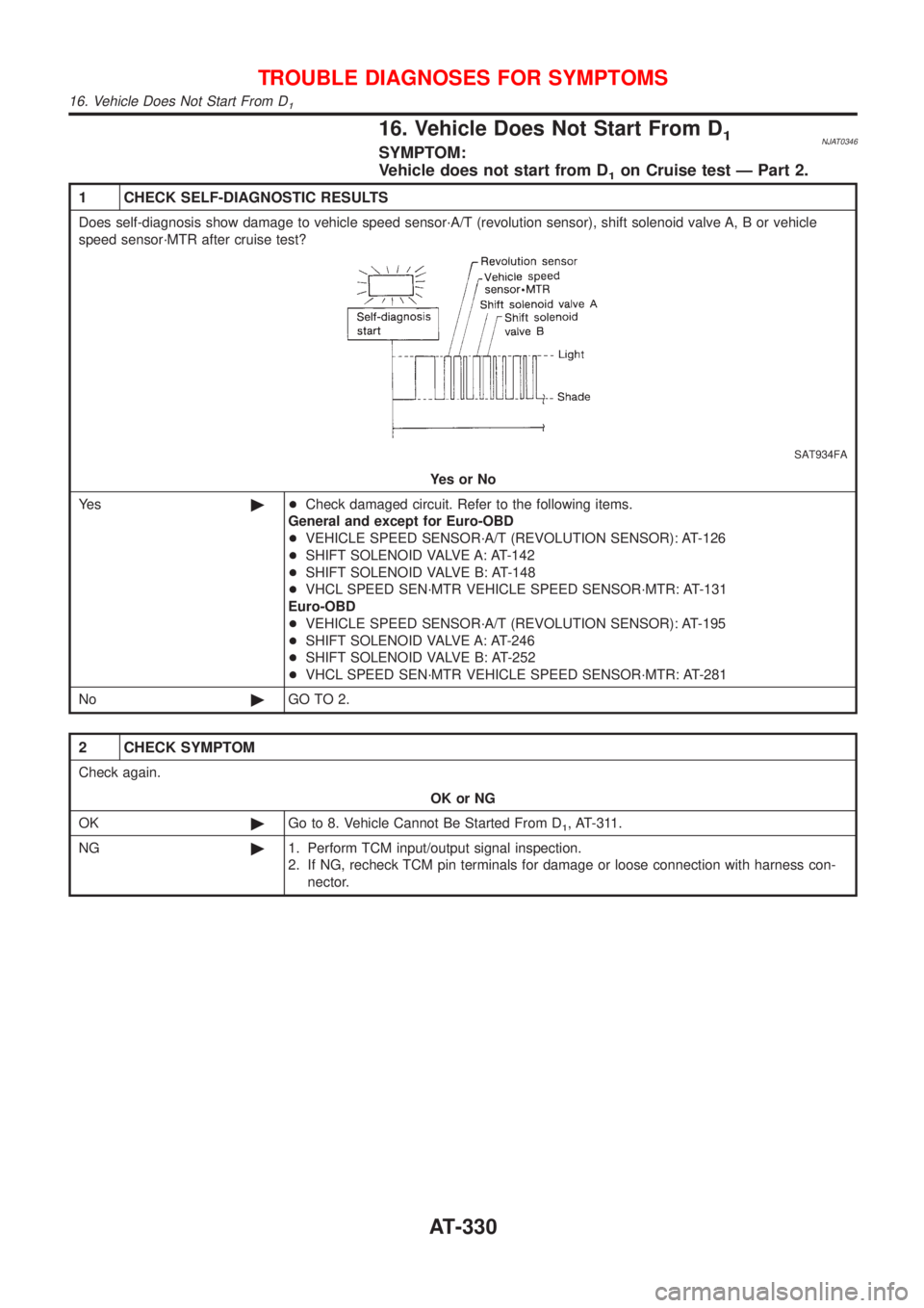
Does self-diagnosis show damage to vehicle speed sensor´A/T (revolution sensor), shift solenoid valve A, B or vehicle
speed sensor´MTR after cruise test?
SAT934FA
YesorNo
Ye s©+Check damaged circuit. Refer to the following items.
General and except for Euro-OBD
+VEHICLE SPEED SENSOR´A/T (REVOLUTION SENSOR): AT-126
+SHIFT SOLENOID VALVE A: AT-142
+SHIFT SOLENOID VALVE B: AT-148
+VHCL SPEED SEN´MTR VEHICLE SPEED SENSOR´MTR: AT-131
Euro-OBD
+VEHICLE SPEED SENSOR´A/T (REVOLUTION SENSOR): AT-195
+SHIFT SOLENOID VALVE A: AT-246
+SHIFT SOLENOID VALVE B: AT-252
+VHCL SPEED SEN´MTR VEHICLE SPEED SENSOR´MTR: AT-281
No©GO TO 2.
2 CHECK SYMPTOM
Check again.
OK or NG
OK©Go to 8. Vehicle Cannot Be Started From D
1, AT-311.
NG©1. Perform TCM input/output signal inspection.
2. If NG, recheck TCM pin terminals for damage or loose connection with harness con-
nector.
TROUBLE DIAGNOSES FOR SYMPTOMS
16. Vehicle Does Not Start From D1
AT-330
Page 355 of 2898
SAT480J
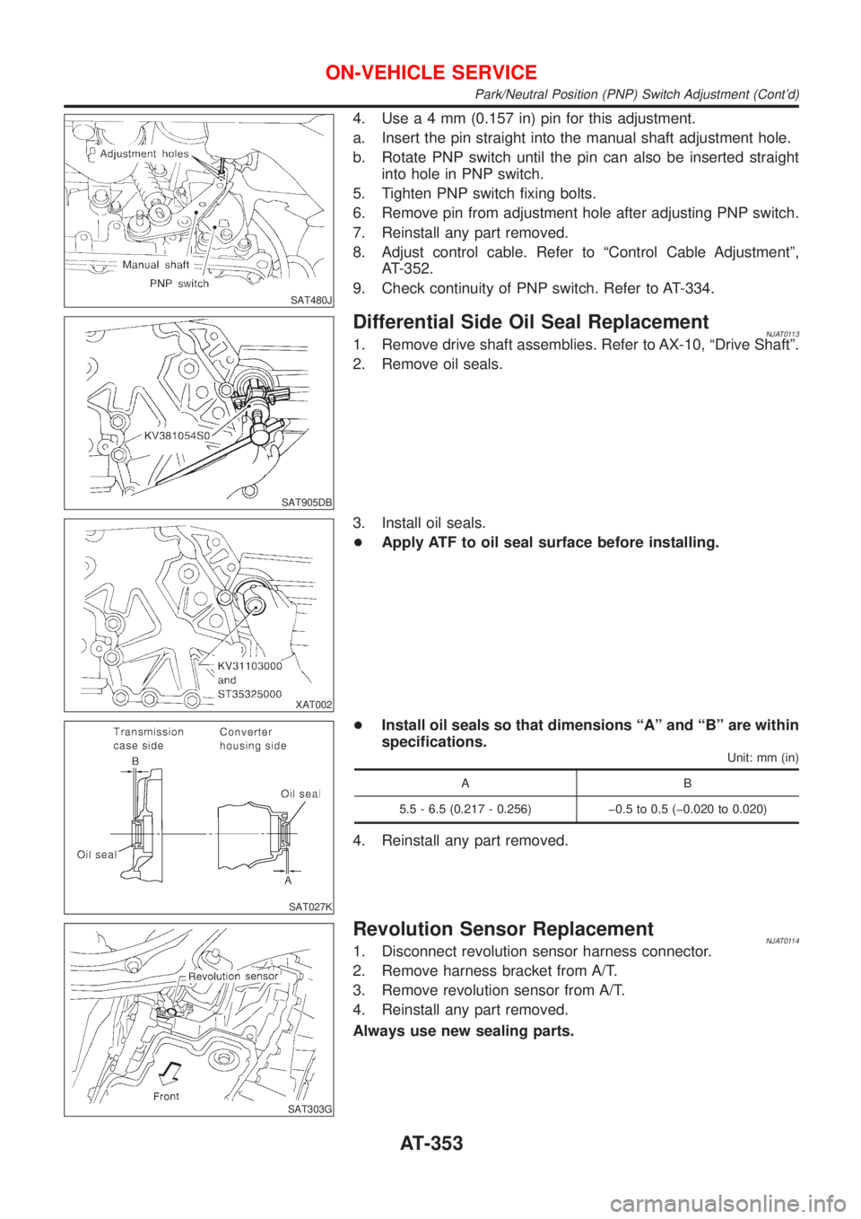
4. Usea4mm(0.157 in) pin for this adjustment.
a. Insert the pin straight into the manual shaft adjustment hole.
b. Rotate PNP switch until the pin can also be inserted straight
into hole in PNP switch.
5. Tighten PNP switch fixing bolts.
6. Remove pin from adjustment hole after adjusting PNP switch.
7. Reinstall any part removed.
8. Adjust control cable. Refer to ªControl Cable Adjustmentº,
AT-352.
9. Check continuity of PNP switch. Refer to AT-334.
SAT905DB
Differential Side Oil Seal ReplacementNJAT01131. Remove drive shaft assemblies. Refer to AX-10, ªDrive Shaftº.
2. Remove oil seals.
XAT002
3. Install oil seals.
+Apply ATF to oil seal surface before installing.
SAT027K
+Install oil seals so that dimensions ªAº and ªBº are within
specifications.
Unit: mm (in)
AB
5.5 - 6.5 (0.217 - 0.256) þ0.5 to 0.5 (þ0.020 to 0.020)
4. Reinstall any part removed.
SAT303G
Revolution Sensor ReplacementNJAT01141. Disconnect revolution sensor harness connector.
2. Remove harness bracket from A/T.
3. Remove revolution sensor from A/T.
4. Reinstall any part removed.
Always use new sealing parts.
ON-VEHICLE SERVICE
Park/Neutral Position (PNP) Switch Adjustment (Cont'd)
AT-353
Page 356 of 2898
SAT065K
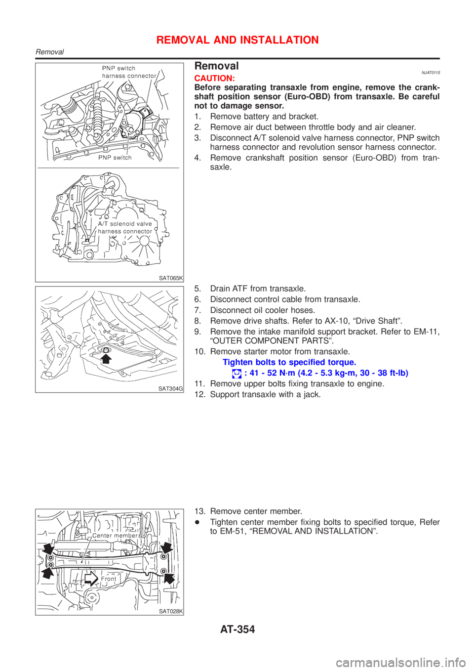
RemovalNJAT0115CAUTION:
Before separating transaxle from engine, remove the crank-
shaft position sensor (Euro-OBD) from transaxle. Be careful
not to damage sensor.
1. Remove battery and bracket.
2. Remove air duct between throttle body and air cleaner.
3. Disconnect A/T solenoid valve harness connector, PNP switch
harness connector and revolution sensor harness connector.
4. Remove crankshaft position sensor (Euro-OBD) from tran-
saxle.
SAT304G
5. Drain ATF from transaxle.
6. Disconnect control cable from transaxle.
7. Disconnect oil cooler hoses.
8. Remove drive shafts. Refer to AX-10, ªDrive Shaftº.
9. Remove the intake manifold support bracket. Refer to EM-11,
ªOUTER COMPONENT PARTSº.
10. Remove starter motor from transaxle.
Tighten bolts to specified torque.
: 41 - 52 N´m (4.2 - 5.3 kg-m, 30 - 38 ft-lb)
11. Remove upper bolts fixing transaxle to engine.
12. Support transaxle with a jack.
SAT028K
13. Remove center member.
+Tighten center member fixing bolts to specified torque, Refer
to EM-51, ªREMOVAL AND INSTALLATIONº.
REMOVAL AND INSTALLATION
Removal
AT-354
Page 382 of 2898

SAT311G
48. Remove revolution sensor from transmission case.
DISASSEMBLY
AT-380
Page 448 of 2898
SAT311G
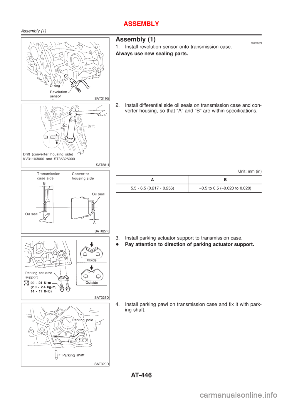
Assembly (1)NJAT01731. Install revolution sensor onto transmission case.
Always use new sealing parts.
SAT881I
2. Install differential side oil seals on transmission case and con-
verter housing, so that ªAº and ªBº are within specifications.
SAT027K
Unit: mm (in)
AB
5.5 - 6.5 (0.217 - 0.256) þ0.5 to 0.5 (þ0.020 to 0.020)
SAT328D
3. Install parking actuator support to transmission case.
+Pay attention to direction of parking actuator support.
SAT329D
4. Install parking pawl on transmission case and fix it with park-
ing shaft.
ASSEMBLY
Assembly (1)
AT-446
Page 487 of 2898
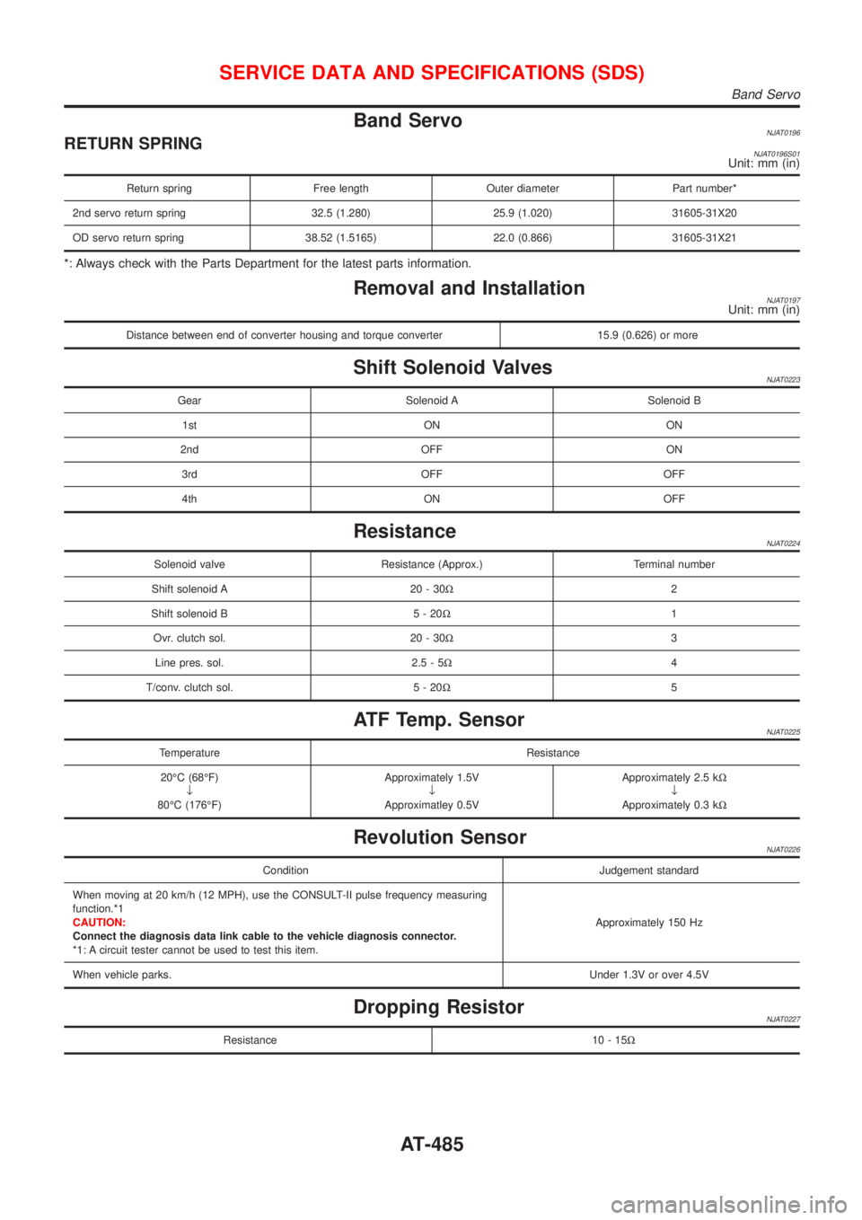
Band ServoNJAT0196RETURN SPRINGNJAT0196S01Unit: mm (in)
Return spring Free length Outer diameter Part number*
2nd servo return spring 32.5 (1.280) 25.9 (1.020) 31605-31X20
OD servo return spring 38.52 (1.5165) 22.0 (0.866) 31605-31X21
*: Always check with the Parts Department for the latest parts information.
Removal and InstallationNJAT0197Unit: mm (in)
Distance between end of converter housing and torque converter 15.9 (0.626) or more
Shift Solenoid ValvesNJAT0223
Gear Solenoid A Solenoid B
1st ON ON
2nd OFF ON
3rd OFF OFF
4th ON OFF
ResistanceNJAT0224
Solenoid valve Resistance (Approx.) Terminal number
Shift solenoid A 20 - 30W2
Shift solenoid B 5 - 20W1
Ovr. clutch sol. 20 - 30W3
Line pres. sol. 2.5 - 5W4
T/conv. clutch sol. 5 - 20W5
ATF Temp. SensorNJAT0225
Temperature Resistance
20ÉC (68ÉF)
¯
80ÉC (176ÉF)Approximately 1.5V
¯
Approximatley 0.5VApproximately 2.5 kW
¯
Approximately 0.3 kW
Revolution SensorNJAT0226
Condition Judgement standard
When moving at 20 km/h (12 MPH), use the CONSULT-II pulse frequency measuring
function.*1
CAUTION:
Connect the diagnosis data link cable to the vehicle diagnosis connector.
*1: A circuit tester cannot be used to test this item.Approximately 150 Hz
When vehicle parks.Under 1.3V or over 4.5V
Dropping ResistorNJAT0227
Resistance 10 - 15W
SERVICE DATA AND SPECIFICATIONS (SDS)
Band Servo
AT-485
Page 493 of 2898
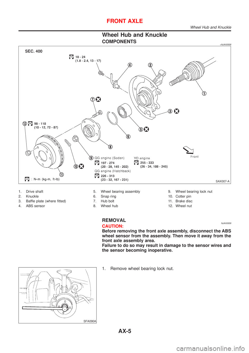
Wheel Hub and Knuckle
COMPONENTS=NJAX0008
SAX007-A
1. Drive shaft
2. Knuckle
3. Baffle plate (where fitted)
4. ABS sensor5. Wheel bearing assembly
6. Snap ring
7. Hub bolt
8. Wheel hub9. Wheel bearing lock nut
10. Cotter pin
11. Brake disc
12. Wheel nut
REMOVALNJAX0009CAUTION:
Before removing the front axle assembly, disconnect the ABS
wheel sensor from the assembly. Then move it away from the
front axle assembly area.
Failure to do so may result in damage to the sensor wires and
the sensor becoming inoperative.
SFA090A
1. Remove wheel bearing lock nut.
FRONT AXLE
Wheel Hub and Knuckle
AX-5
Page 510 of 2898
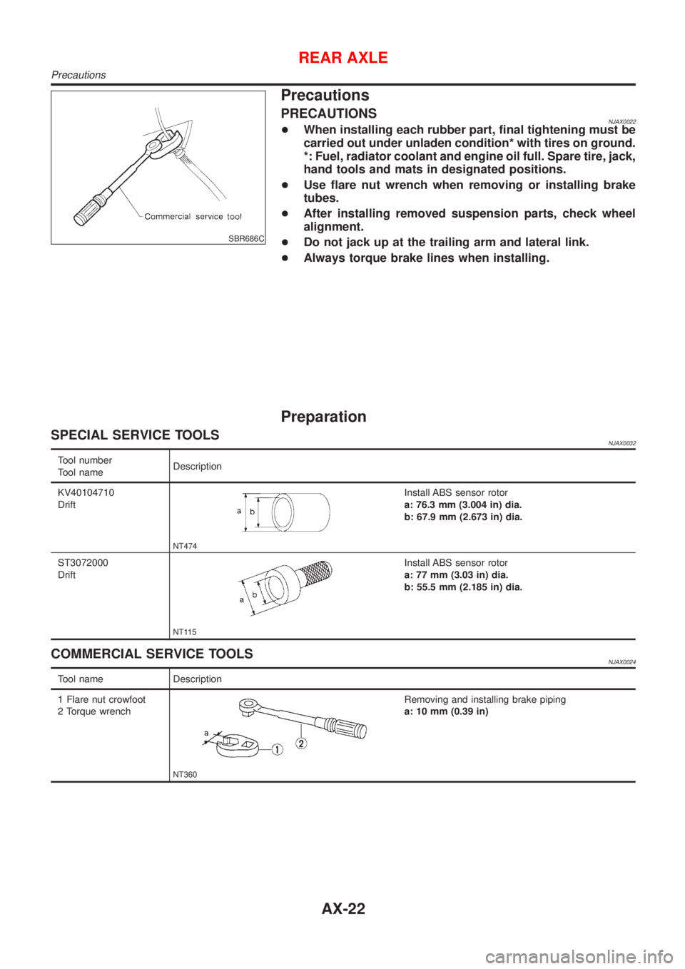
SBR686C
Precautions
PRECAUTIONSNJAX0022+When installing each rubber part, final tightening must be
carried out under unladen condition* with tires on ground.
*: Fuel, radiator coolant and engine oil full. Spare tire, jack,
hand tools and mats in designated positions.
+Use flare nut wrench when removing or installing brake
tubes.
+After installing removed suspension parts, check wheel
alignment.
+Do not jack up at the trailing arm and lateral link.
+Always torque brake lines when installing.
Preparation
SPECIAL SERVICE TOOLSNJAX0032
Tool number
Tool nameDescription
KV40104710
Drift
NT474
Install ABS sensor rotor
a: 76.3 mm (3.004 in) dia.
b: 67.9 mm (2.673 in) dia.
ST3072000
Drift
NT115
Install ABS sensor rotor
a: 77 mm (3.03 in) dia.
b: 55.5 mm (2.185 in) dia.
COMMERCIAL SERVICE TOOLSNJAX0024
Tool name Description
1 Flare nut crowfoot
2 Torque wrench
NT360
Removing and installing brake piping
a: 10 mm (0.39 in)
REAR AXLE
Precautions
AX-22