NISSAN ALMERA 2001 Service Manual
ALMERA 2001
NISSAN
NISSAN
https://www.carmanualsonline.info/img/5/57348/w960_57348-0.png
NISSAN ALMERA 2001 Service Manual
Trending: headlamp, service interval, maintenance, roof rack, fog light bulb, warning, engine overheat
Page 2331 of 2898
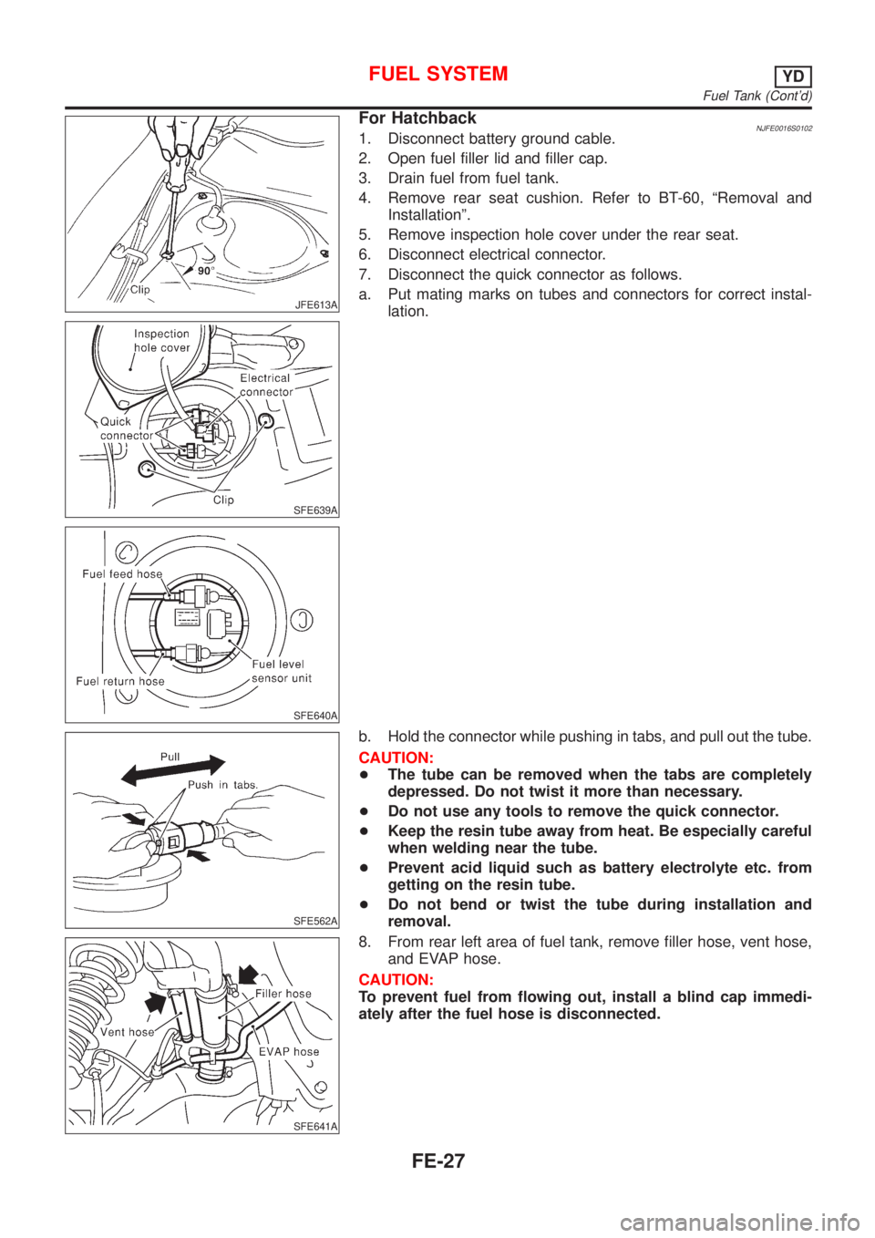
JFE613A
SFE639A
SFE640A
For HatchbackNJFE0016S01021. Disconnect battery ground cable.
2. Open fuel filler lid and filler cap.
3. Drain fuel from fuel tank.
4. Remove rear seat cushion. Refer to BT-60, ªRemoval and
Installationº.
5. Remove inspection hole cover under the rear seat.
6. Disconnect electrical connector.
7. Disconnect the quick connector as follows.
a. Put mating marks on tubes and connectors for correct instal-
lation.
SFE562A
b. Hold the connector while pushing in tabs, and pull out the tube.
CAUTION:
+The tube can be removed when the tabs are completely
depressed. Do not twist it more than necessary.
+Do not use any tools to remove the quick connector.
+Keep the resin tube away from heat. Be especially careful
when welding near the tube.
+Prevent acid liquid such as battery electrolyte etc. from
getting on the resin tube.
+Do not bend or twist the tube during installation and
removal.
SFE641A
8. From rear left area of fuel tank, remove filler hose, vent hose,
and EVAP hose.
CAUTION:
To prevent fuel from flowing out, install a blind cap immedi-
ately after the fuel hose is disconnected.
FUEL SYSTEMYD
Fuel Tank (Cont'd)
FE-27
Page 2332 of 2898
SFE642A
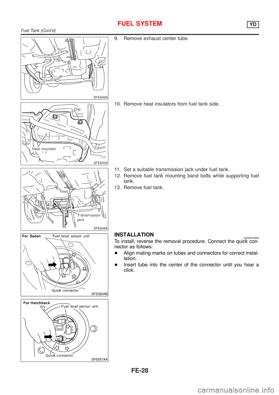
9. Remove exhaust center tube.
SFE643A
10. Remove heat insulators from fuel tank side.
SFE644A
11. Set a suitable transmission jack under fuel tank.
12. Remove fuel tank mounting band bolts while supporting fuel
tank.
13. Remove fuel tank.
SFE560AB
SFE657AA
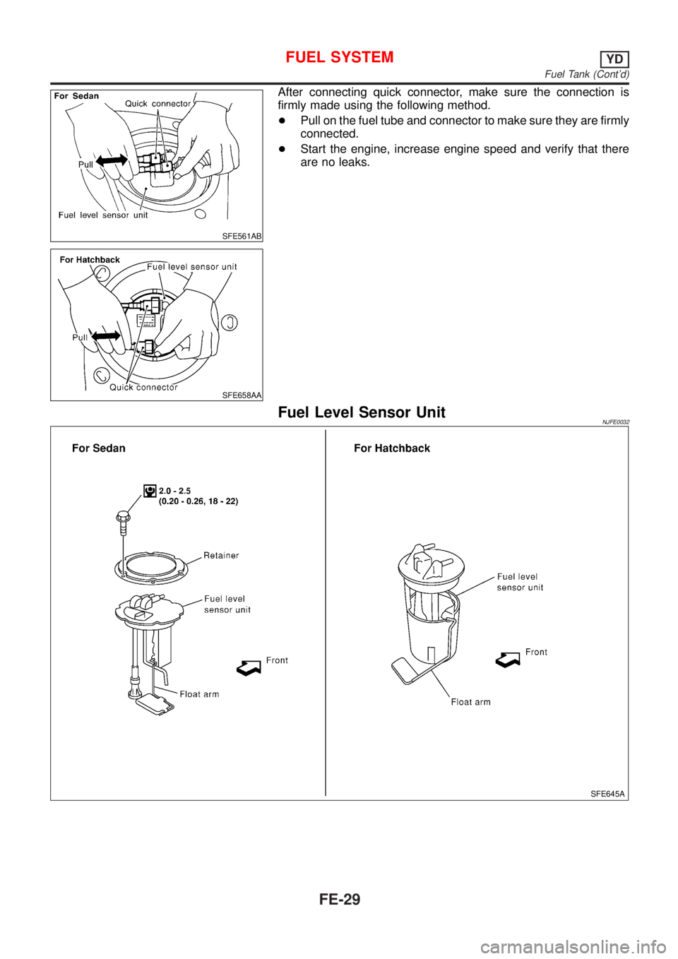
INSTALLATIONNJFE0016S02To install, reverse the removal procedure. Connect the quick con-
nector as follows:
+Align mating marks on tubes and connectors for correct instal-
lation.
+Insert tube into the center of the connector until you hear a
click.
FUEL SYSTEMYD
Fuel Tank (Cont'd)
FE-28
Page 2333 of 2898
SFE561AB
SFE658AA
After connecting quick connector, make sure the connection is
firmly made using the following method.
+Pull on the fuel tube and connector to make sure they are firmly
connected.
+Start the engine, increase engine speed and verify that there
are no leaks.
Fuel Level Sensor UnitNJFE0032
SFE645A
FUEL SYSTEMYD
Fuel Tank (Cont'd)
FE-29
Page 2334 of 2898
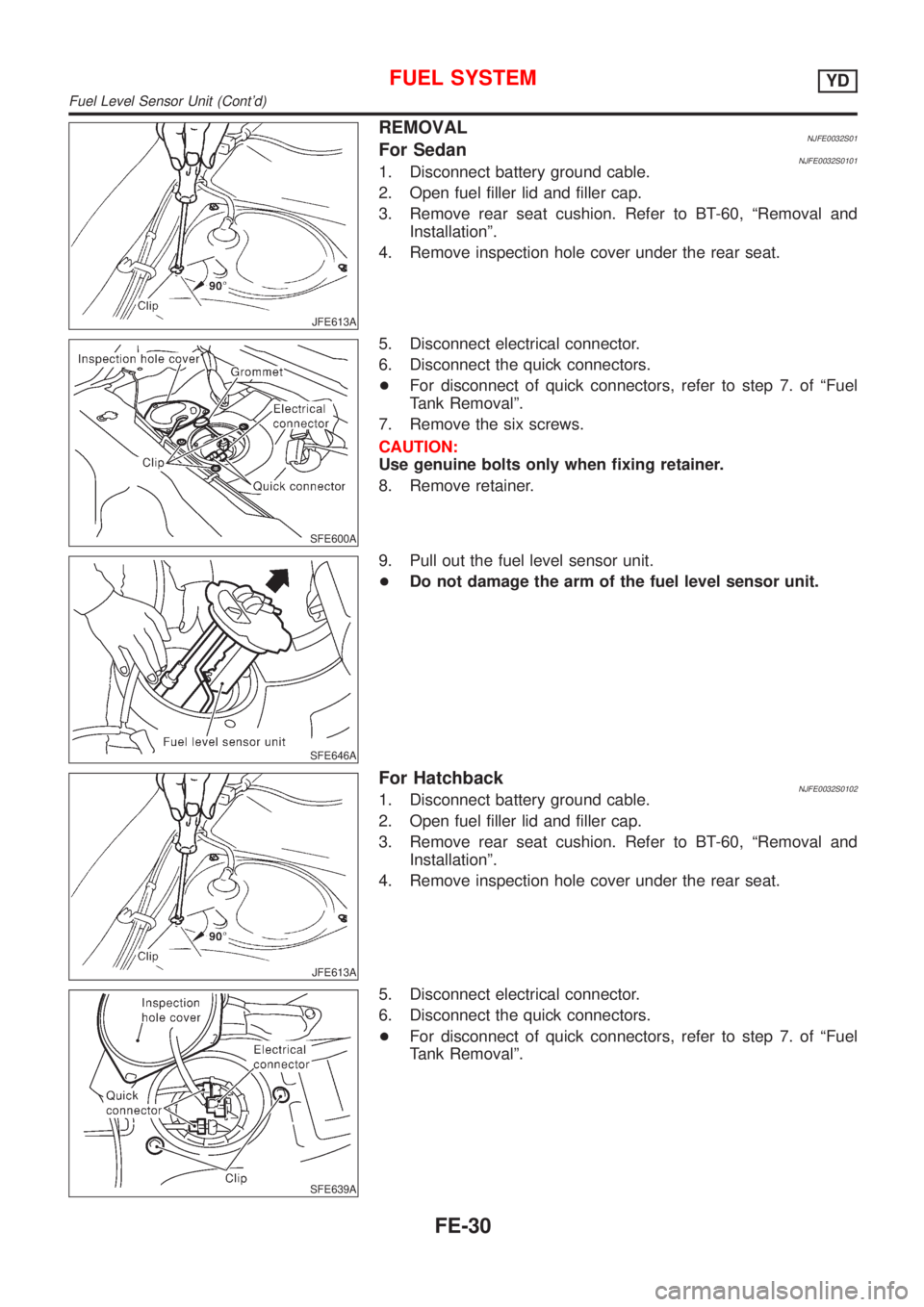
JFE613A
REMOVALNJFE0032S01For SedanNJFE0032S01011. Disconnect battery ground cable.
2. Open fuel filler lid and filler cap.
3. Remove rear seat cushion. Refer to BT-60, ªRemoval and
Installationº.
4. Remove inspection hole cover under the rear seat.
SFE600A
5. Disconnect electrical connector.
6. Disconnect the quick connectors.
+For disconnect of quick connectors, refer to step 7. of ªFuel
Tank Removalº.
7. Remove the six screws.
CAUTION:
Use genuine bolts only when fixing retainer.
8. Remove retainer.
SFE646A
9. Pull out the fuel level sensor unit.
+Do not damage the arm of the fuel level sensor unit.
JFE613A
For HatchbackNJFE0032S01021. Disconnect battery ground cable.
2. Open fuel filler lid and filler cap.
3. Remove rear seat cushion. Refer to BT-60, ªRemoval and
Installationº.
4. Remove inspection hole cover under the rear seat.
SFE639A
5. Disconnect electrical connector.
6. Disconnect the quick connectors.
+For disconnect of quick connectors, refer to step 7. of ªFuel
Tank Removalº.
FUEL SYSTEMYD
Fuel Level Sensor Unit (Cont'd)
FE-30
Page 2335 of 2898
SFE376A
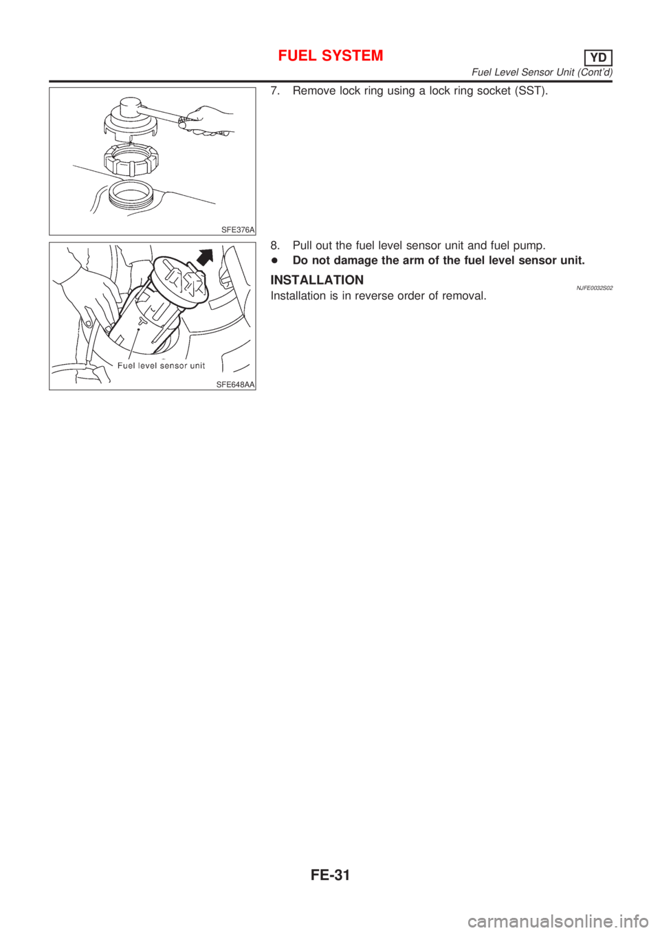
7. Remove lock ring using a lock ring socket (SST).
SFE648AA
8. Pull out the fuel level sensor unit and fuel pump.
+Do not damage the arm of the fuel level sensor unit.
INSTALLATIONNJFE0032S02Installation is in reverse order of removal.
FUEL SYSTEMYD
Fuel Level Sensor Unit (Cont'd)
FE-31
Page 2336 of 2898
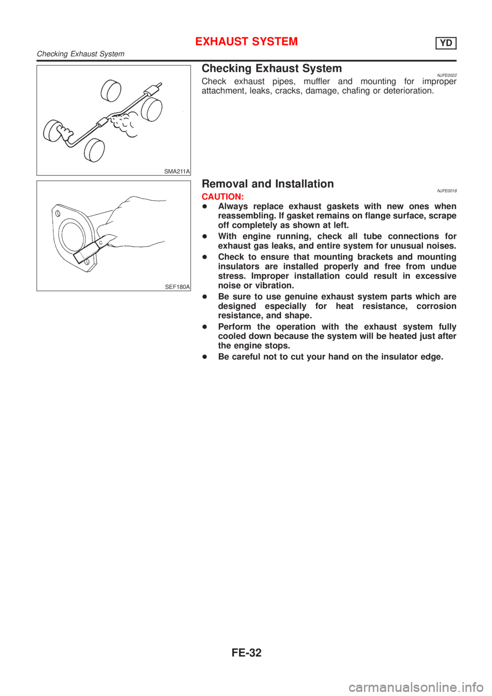
SMA211A
Checking Exhaust SystemNJFE0022Check exhaust pipes, muffler and mounting for improper
attachment, leaks, cracks, damage, chafing or deterioration.
SEF180A
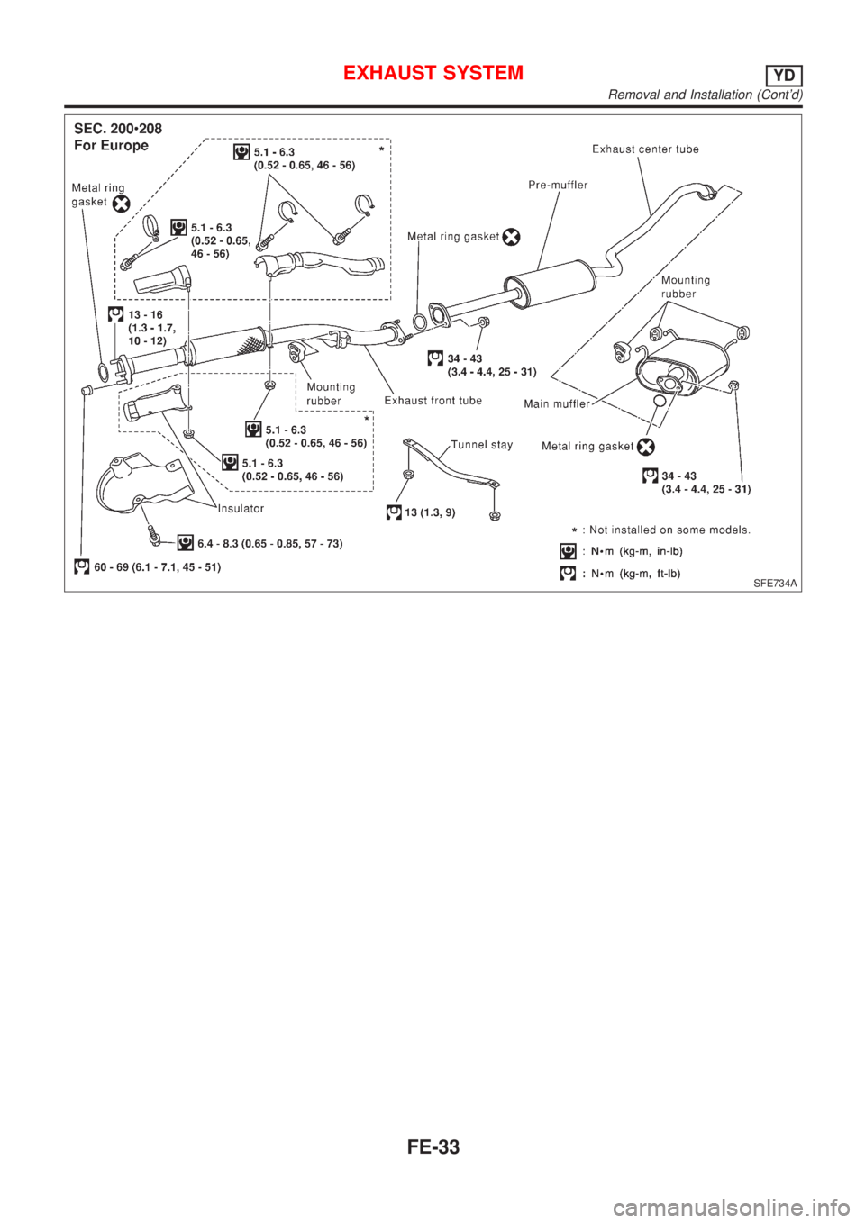
Removal and InstallationNJFE0018CAUTION:
+Always replace exhaust gaskets with new ones when
reassembling. If gasket remains on flange surface, scrape
off completely as shown at left.
+With engine running, check all tube connections for
exhaust gas leaks, and entire system for unusual noises.
+Check to ensure that mounting brackets and mounting
insulators are installed properly and free from undue
stress. Improper installation could result in excessive
noise or vibration.
+Be sure to use genuine exhaust system parts which are
designed especially for heat resistance, corrosion
resistance, and shape.
+Perform the operation with the exhaust system fully
cooled down because the system will be heated just after
the engine stops.
+Be careful not to cut your hand on the insulator edge.
EXHAUST SYSTEMYD
Checking Exhaust System
FE-32
Page 2337 of 2898
SFE734A
EXHAUST SYSTEMYD
Removal and Installation (Cont'd)
FE-33
Page 2338 of 2898
EXHAUST SYSTEM
Removal and Installation (Cont'd)
FE-34
Page 2339 of 2898
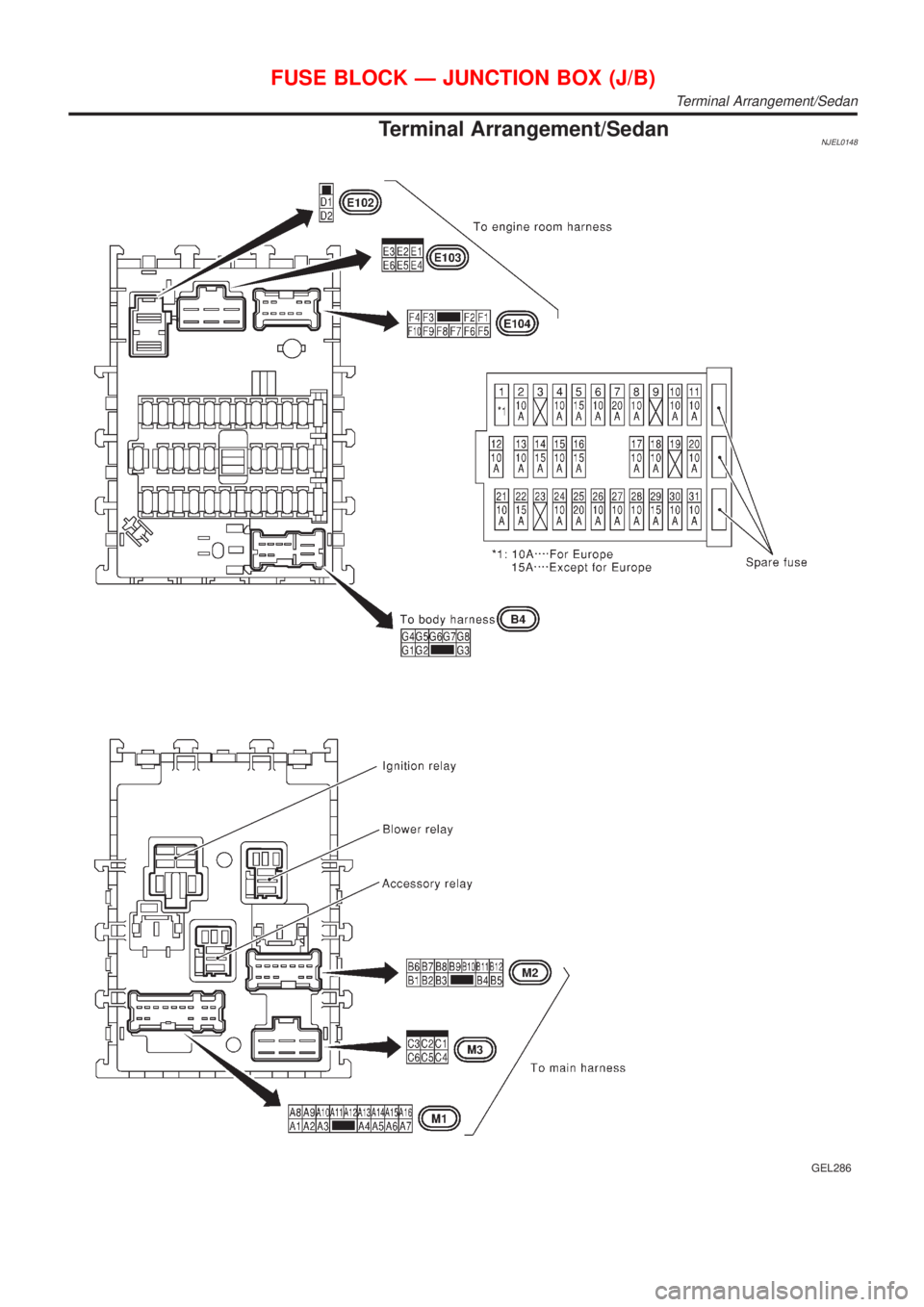
Termina lArrangement/Sedan
GEL286
Terminal Arrangement/Sedan
Page 2340 of 2898
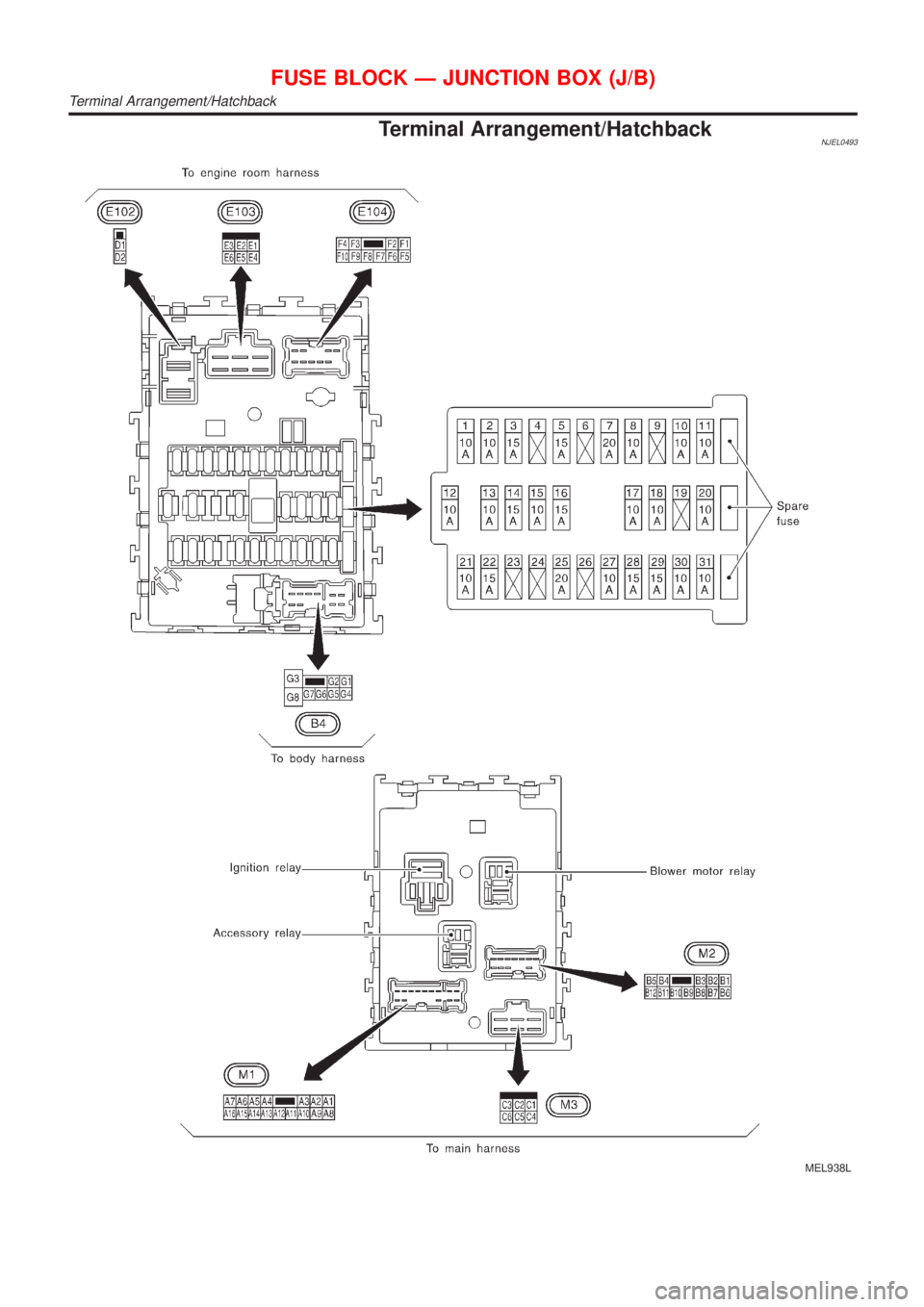
Termina lArrangement/Hatchback
MEL938L
Terminal Arrangement/Hatchback
Trending: cooling, warning lights, open gas tank, cruise control, maintenance schedule, headrest, steering wheel adjustment

