NISSAN ALMERA 2001 Service Manual
ALMERA 2001
NISSAN
NISSAN
https://www.carmanualsonline.info/img/5/57348/w960_57348-0.png
NISSAN ALMERA 2001 Service Manual
Trending: roof, engine oil, child restraint, parking sensors, dimensions, center console, fuel filter
Page 2861 of 2898
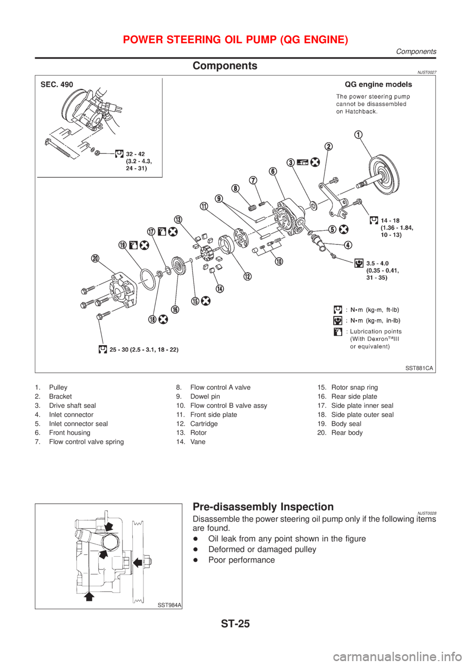
ComponentsNJST0027
SST881CA
1. Pulley
2. Bracket
3. Drive shaft seal
4. Inlet connector
5. Inlet connector seal
6. Front housing
7. Flow control valve spring8. Flow control A valve
9. Dowel pin
10. Flow control B valve assy
11. Front side plate
12. Cartridge
13. Rotor
14. Vane15. Rotor snap ring
16. Rear side plate
17. Side plate inner seal
18. Side plate outer seal
19. Body seal
20. Rear body
SST984A
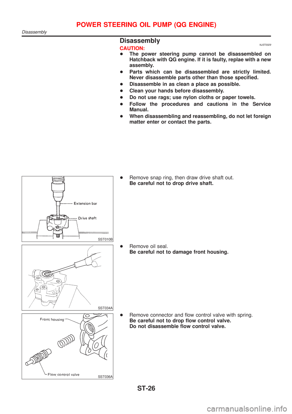
Pre-disassembly InspectionNJST0028Disassemble the power steering oil pump only if the following items
are found.
+Oil leak from any point shown in the figure
+Deformed or damaged pulley
+Poor performance
POWER STEERING OIL PUMP (QG ENGINE)
Components
ST-25
Page 2862 of 2898
DisassemblyNJST0029CAUTION:
+The power steering pump cannot be disassembled on
Hatchback with QG engine. If it is faulty, replae with a new
assembly.
+Parts which can be disassembled are strictly limited.
Never disassemble parts other than those specified.
+Disassemble in as clean a place as possible.
+Clean your hands before disassembly.
+Do not use rags; use nylon cloths or paper towels.
+Follow the procedures and cautions in the Service
Manual.
+When disassembling and reassembling, do not let foreign
matter enter or contact the parts.
SST010B
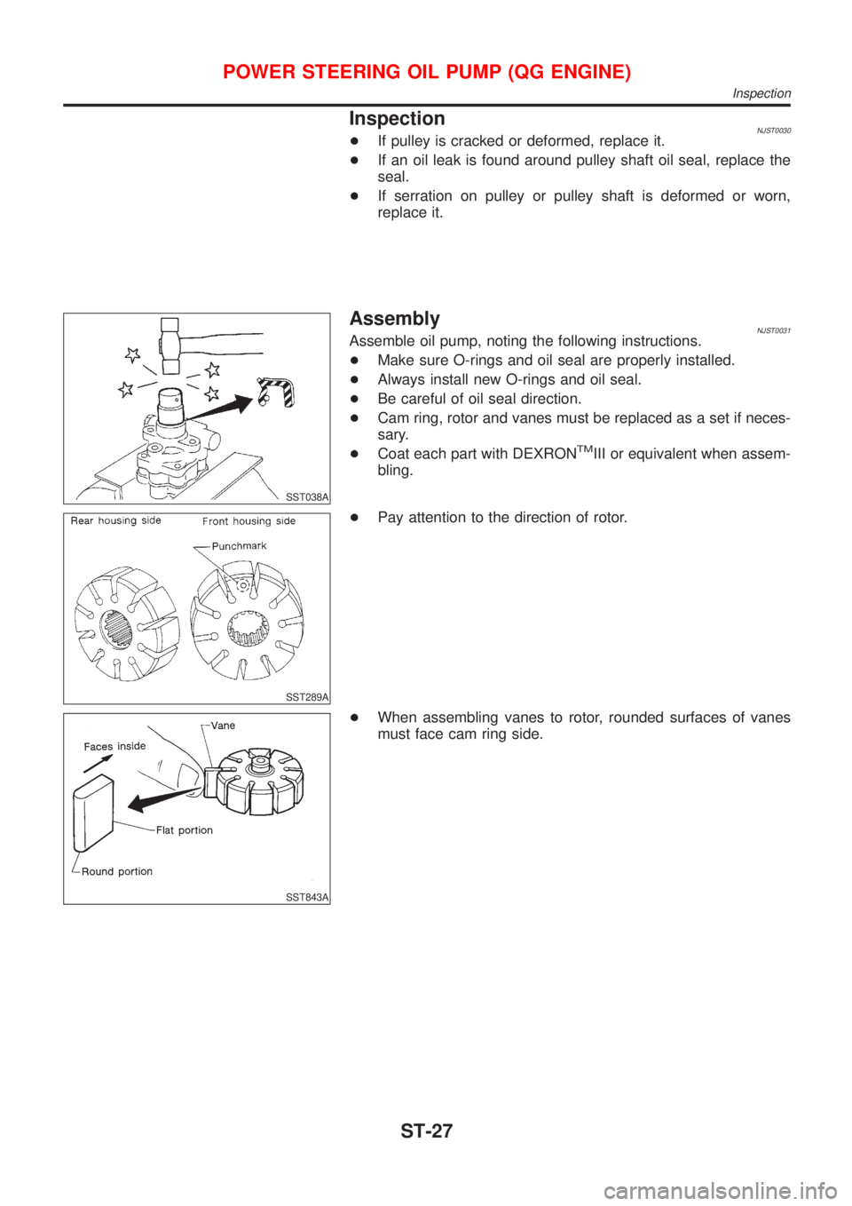
+Remove snap ring, then draw drive shaft out.
Be careful not to drop drive shaft.
SST034A
+Remove oil seal.
Be careful not to damage front housing.
SST036A
+Remove connector and flow control valve with spring.
Be careful not to drop flow control valve.
Do not disassemble flow control valve.
POWER STEERING OIL PUMP (QG ENGINE)
Disassembly
ST-26
Page 2863 of 2898
InspectionNJST0030+If pulley is cracked or deformed, replace it.
+If an oil leak is found around pulley shaft oil seal, replace the
seal.
+If serration on pulley or pulley shaft is deformed or worn,
replace it.
SST038A
AssemblyNJST0031Assemble oil pump, noting the following instructions.
+Make sure O-rings and oil seal are properly installed.
+Always install new O-rings and oil seal.
+Be careful of oil seal direction.
+Cam ring, rotor and vanes must be replaced as a set if neces-
sary.
+Coat each part with DEXRON
TMIII or equivalent when assem-
bling.
SST289A
+Pay attention to the direction of rotor.
SST843A
+When assembling vanes to rotor, rounded surfaces of vanes
must face cam ring side.
POWER STEERING OIL PUMP (QG ENGINE)
Inspection
ST-27
Page 2864 of 2898
SST472C
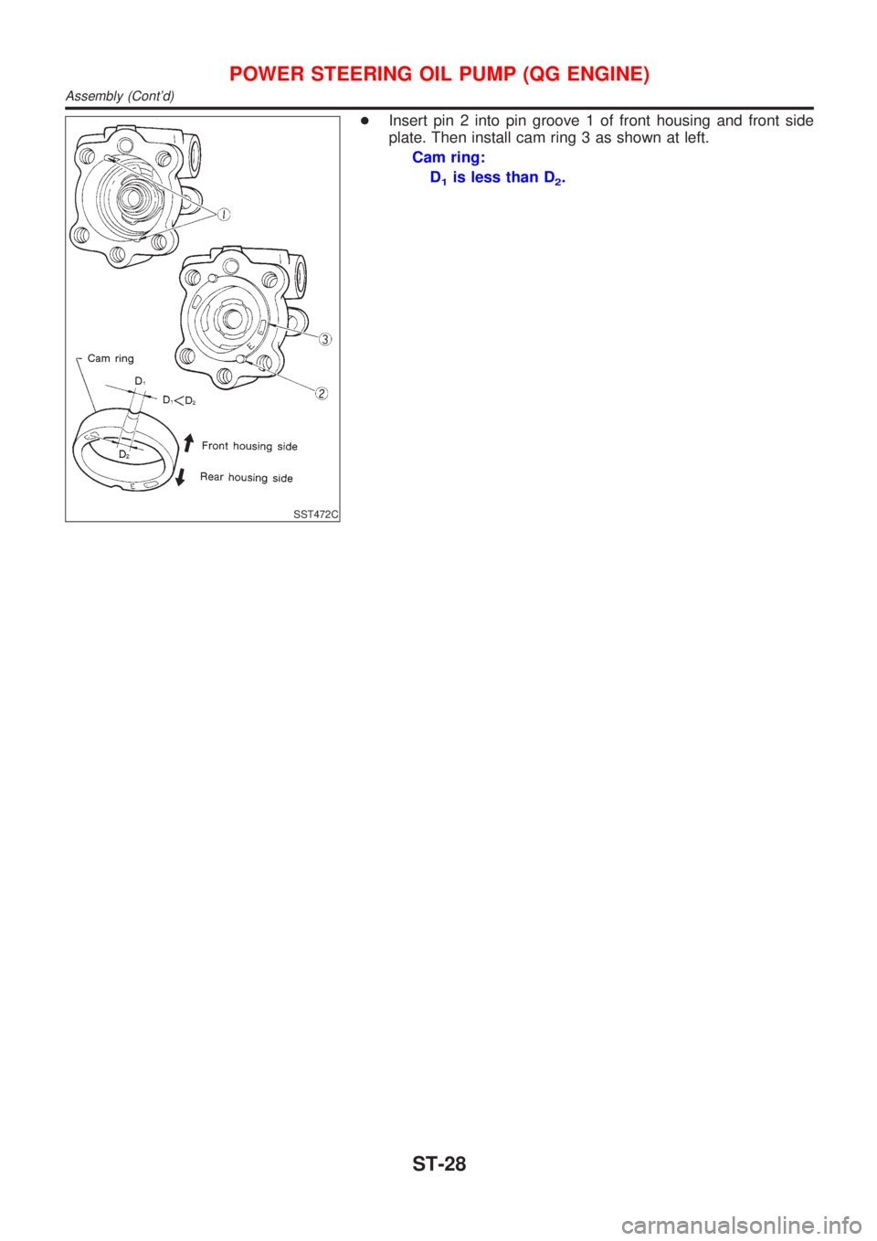
+Insert pin 2 into pin groove 1 of front housing and front side
plate. Then install cam ring 3 as shown at left.
Cam ring:
D
1is less than D2.
POWER STEERING OIL PUMP (QG ENGINE)
Assembly (Cont'd)
ST-28
Page 2865 of 2898
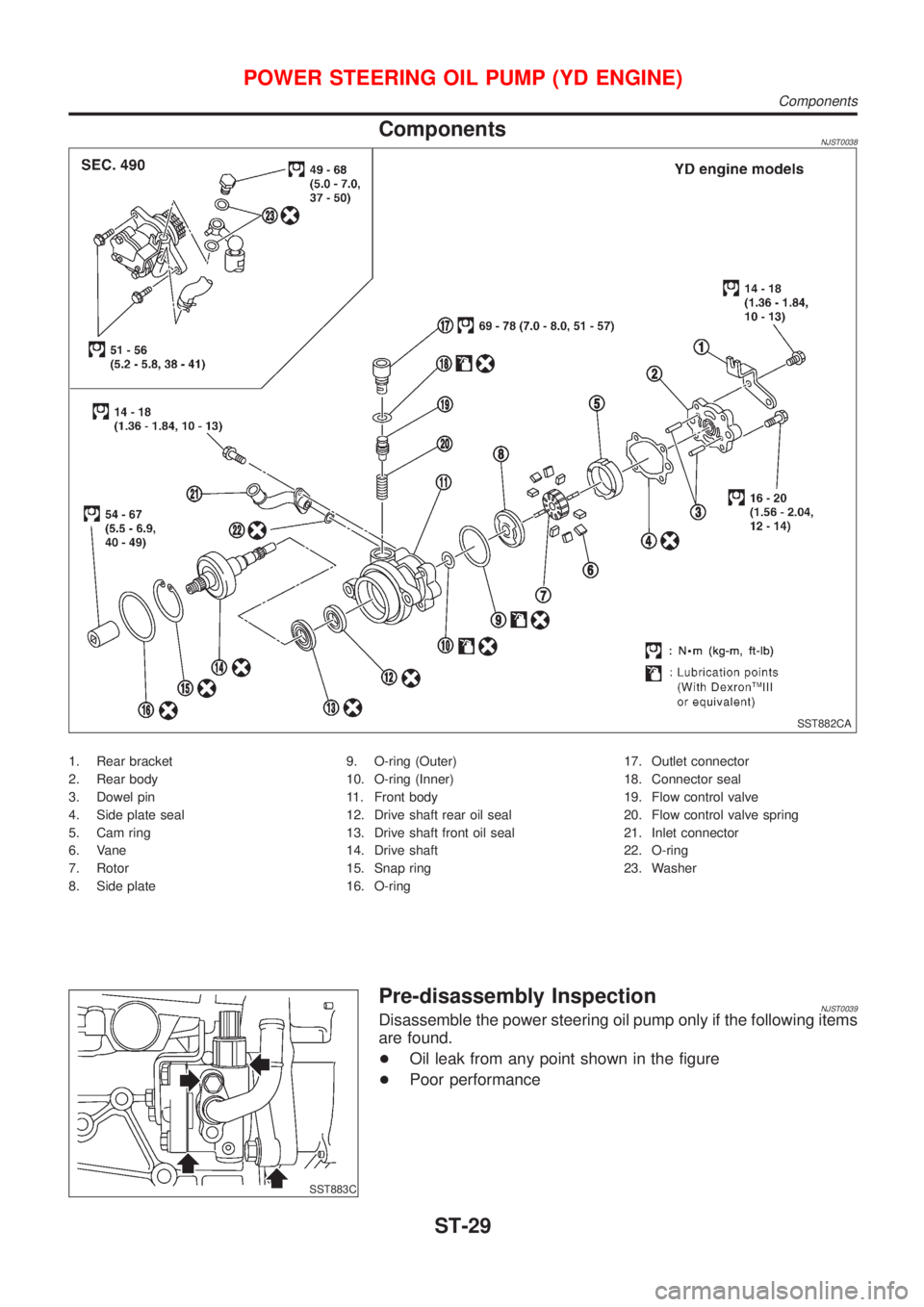
ComponentsNJST0038
SST882CA
1. Rear bracket
2. Rear body
3. Dowel pin
4. Side plate seal
5. Cam ring
6. Vane
7. Rotor
8. Side plate9. O-ring (Outer)
10. O-ring (Inner)
11. Front body
12. Drive shaft rear oil seal
13. Drive shaft front oil seal
14. Drive shaft
15. Snap ring
16. O-ring17. Outlet connector
18. Connector seal
19. Flow control valve
20. Flow control valve spring
21. Inlet connector
22. O-ring
23. Washer
SST883C
Pre-disassembly InspectionNJST0039Disassemble the power steering oil pump only if the following items
are found.
+Oil leak from any point shown in the figure
+Poor performance
POWER STEERING OIL PUMP (YD ENGINE)
Components
ST-29
Page 2866 of 2898
SST884C
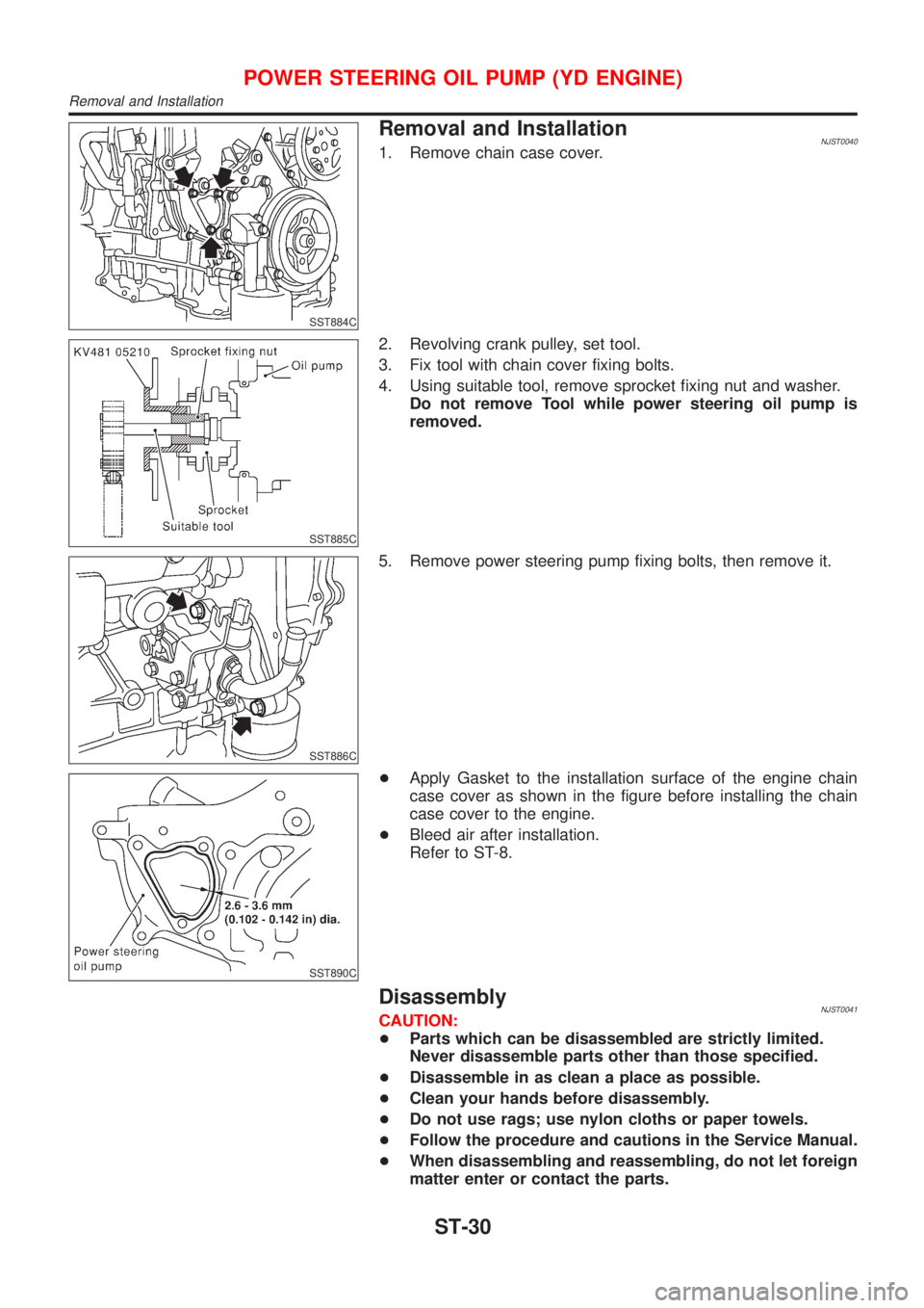
Removal and InstallationNJST00401. Remove chain case cover.
SST885C
2. Revolving crank pulley, set tool.
3. Fix tool with chain cover fixing bolts.
4. Using suitable tool, remove sprocket fixing nut and washer.
Do not remove Tool while power steering oil pump is
removed.
SST886C
5. Remove power steering pump fixing bolts, then remove it.
SST890C
+Apply Gasket to the installation surface of the engine chain
case cover as shown in the figure before installing the chain
case cover to the engine.
+Bleed air after installation.
Refer to ST-8.
DisassemblyNJST0041CAUTION:
+Parts which can be disassembled are strictly limited.
Never disassemble parts other than those specified.
+Disassemble in as clean a place as possible.
+Clean your hands before disassembly.
+Do not use rags; use nylon cloths or paper towels.
+Follow the procedure and cautions in the Service Manual.
+When disassembling and reassembling, do not let foreign
matter enter or contact the parts.
POWER STEERING OIL PUMP (YD ENGINE)
Removal and Installation
ST-30
Page 2867 of 2898
SST887C
+Remove rear bracket and rear body.
+Remove side plate seal, cam ring vane, rotor side and plate.
SST036A
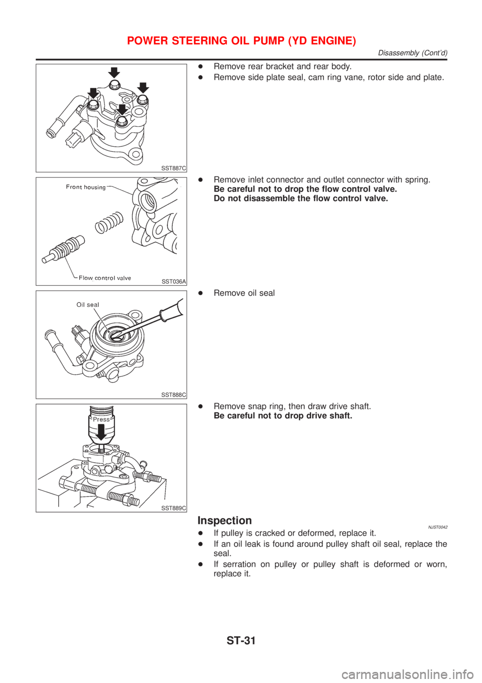
+Remove inlet connector and outlet connector with spring.
Be careful not to drop the flow control valve.
Do not disassemble the flow control valve.
SST888C
+Remove oil seal
SST889C
+Remove snap ring, then draw drive shaft.
Be careful not to drop drive shaft.
InspectionNJST0042+If pulley is cracked or deformed, replace it.
+If an oil leak is found around pulley shaft oil seal, replace the
seal.
+If serration on pulley or pulley shaft is deformed or worn,
replace it.
POWER STEERING OIL PUMP (YD ENGINE)
Disassembly (Cont'd)
ST-31
Page 2868 of 2898
SST038A
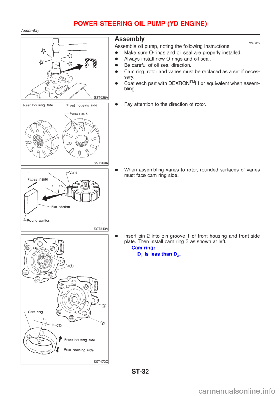
AssemblyNJST0043Assemble oil pump, noting the following instructions.
+Make sure O-rings and oil seal are properly installed.
+Always install new O-rings and oil seal.
+Be careful of oil seal direction.
+Cam ring, rotor and vanes must be replaced as a set if neces-
sary.
+Coat each part with DEXRON
TMIII or equivalent when assem-
bling.
SST289A
+Pay attention to the direction of rotor.
SST843A
+When assembling vanes to rotor, rounded surfaces of vanes
must face cam ring side.
SST472C
+Insert pin 2 into pin groove 1 of front housing and front side
plate. Then install cam ring 3 as shown at left.
Cam ring:
D
1is less than D2.
POWER STEERING OIL PUMP (YD ENGINE)
Assembly
ST-32
Page 2869 of 2898
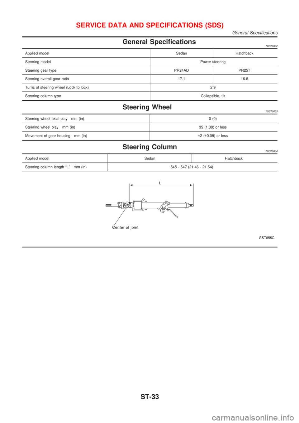
General SpecificationsNJST0032
Applied modelSedan Hatchback
Steering modelPower steering
Steering gear type PR24AD PR25T
Steering overall gear ratio 17.1 16.8
Turns of steering wheel (Lock to lock)2.9
Steering column typeCollapsible, tilt
Steering WheelNJST0033
Steering wheel axial play mm (in)0 (0)
Steering wheel play mm (in)35 (1.38) or less
Movement of gear housing mm (in)±2(±0.08) or less
Steering ColumnNJST0034
Applied model Sedan Hatchback
Steering column length ªLº mm (in) 545 - 547 (21.46 - 21.54)
SST855C
SERVICE DATA AND SPECIFICATIONS (SDS)
General Specifications
ST-33
Page 2870 of 2898
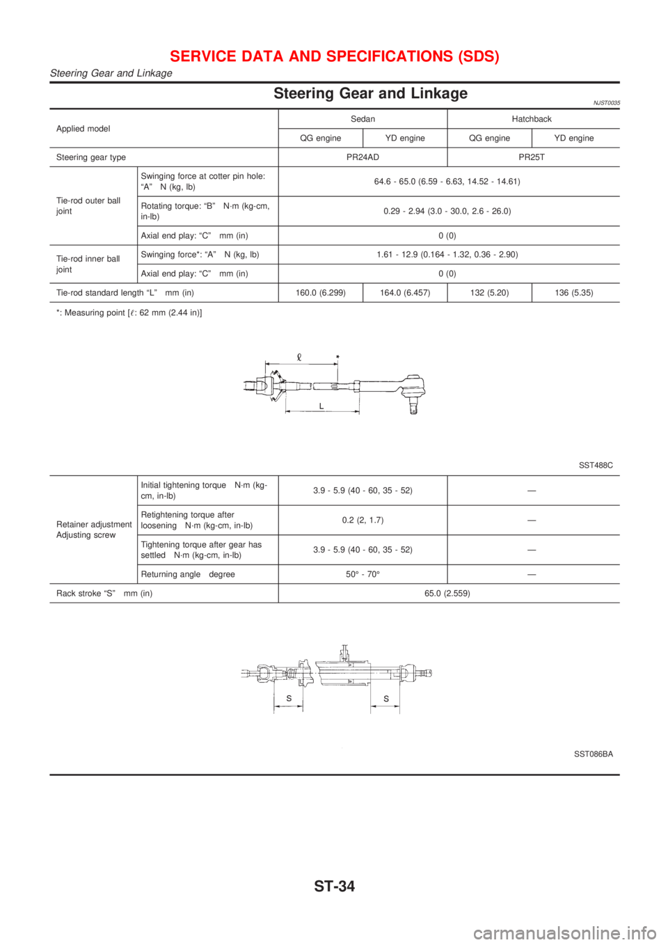
Steering Gear and LinkageNJST0035
Applied modelSedan Hatchback
QG engine YD engine QG engine YD engine
Steering gear type PR24AD PR25T
Tie-rod outer ball
jointSwinging force at cotter pin hole:
ªAº N (kg, lb)64.6 - 65.0 (6.59 - 6.63, 14.52 - 14.61)
Rotating torque: ªBº N´m (kg-cm,
in-lb)0.29 - 2.94 (3.0 - 30.0, 2.6 - 26.0)
Axial end play: ªCº mm (in) 0 (0)
Tie-rod inner ball
jointSwinging force*: ªAº N (kg, lb) 1.61 - 12.9 (0.164 - 1.32, 0.36 - 2.90)
Axial end play: ªCº mm (in) 0 (0)
Tie-rod standard length ªLº mm (in) 160.0 (6.299) 164.0 (6.457) 132 (5.20) 136 (5.35)
*: Measuring point [!: 62 mm (2.44 in)]
SST488C
Retainer adjustment
Adjusting screwInitial tightening torque N´m (kg-
cm, in-lb)3.9 - 5.9 (40 - 60, 35 - 52) Ð
Retightening torque after
loosening N´m (kg-cm, in-lb)0.2 (2, 1.7) Ð
Tightening torque after gear has
settled N´m (kg-cm, in-lb)3.9 - 5.9 (40 - 60, 35 - 52) Ð
Returning angle degree 50É - 70É Ð
Rack stroke ªSº mm (in)65.0 (2.559)
SST086BA
SERVICE DATA AND SPECIFICATIONS (SDS)
Steering Gear and Linkage
ST-34
Trending: lock, headrest, timing belt, height, dimensions, window, instrument panel
