Assembly NISSAN ALMERA 2001 Owner's Guide
[x] Cancel search | Manufacturer: NISSAN, Model Year: 2001, Model line: ALMERA, Model: NISSAN ALMERA 2001Pages: 2898, PDF Size: 60.76 MB
Page 210 of 2898
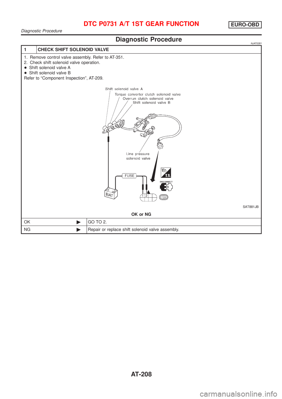
Diagnostic ProcedureNJAT0281
1 CHECK SHIFT SOLENOID VALVE
1. Remove control valve assembly. Refer to AT-351.
2. Check shift solenoid valve operation.
+Shift solenoid valve A
+Shift solenoid valve B
Refer to ªComponent Inspectionº, AT-209.
SAT881JB
OK or NG
OK©GO TO 2.
NG©Repair or replace shift solenoid valve assembly.
DTC P0731 A/T 1ST GEAR FUNCTIONEURO-OBD
Diagnostic Procedure
AT-208
Page 211 of 2898
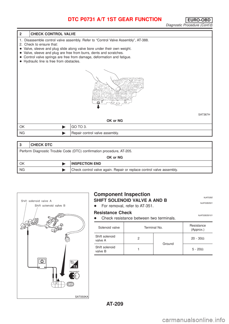
2 CHECK CONTROL VALVE
1. Disassemble control valve assembly. Refer to ªControl Valve Assemblyº, AT-388.
2. Check to ensure that:
+Valve, sleeve and plug slide along valve bore under their own weight.
+Valve, sleeve and plug are free from burrs, dents and scratches.
+Control valve springs are free from damage, deformation and fatigue.
+Hydraulic line is free from obstacles.
SAT367H
OK or NG
OK©GO TO 3.
NG©Repair control valve assembly.
3 CHECK DTC
Perform Diagnostic Trouble Code (DTC) confirmation procedure, AT-205.
OK or NG
OK©INSPECTION END
NG©Check control valve again. Repair or replace control valve assembly.
SAT050KA
Component InspectionNJAT0282SHIFT SOLENOID VALVE A AND BNJAT0282S01+For removal, refer to AT-351.
Resistance CheckNJAT0282S0101+Check resistance between two terminals.
Solenoid valve Terminal No.Resistance
(Approx.)
Shift solenoid
valve A2
Ground20-30W
Shift solenoid
valve B1 5-20W
DTC P0731 A/T 1ST GEAR FUNCTIONEURO-OBD
Diagnostic Procedure (Cont'd)
AT-209
Page 217 of 2898
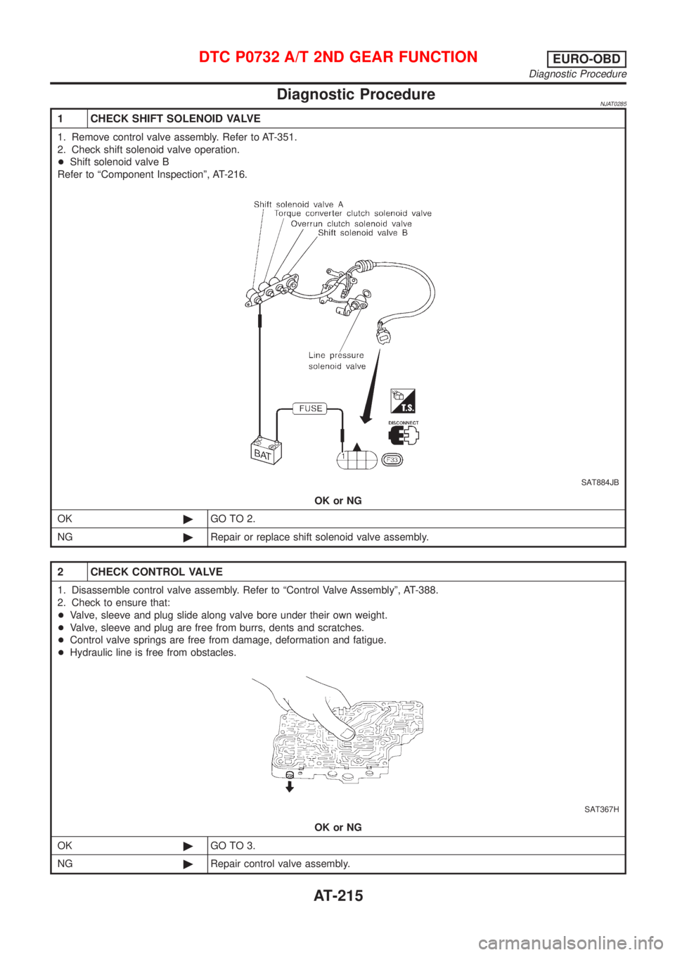
Diagnostic ProcedureNJAT0285
1 CHECK SHIFT SOLENOID VALVE
1. Remove control valve assembly. Refer to AT-351.
2. Check shift solenoid valve operation.
+Shift solenoid valve B
Refer to ªComponent Inspectionº, AT-216.
SAT884JB
OK or NG
OK©GO TO 2.
NG©Repair or replace shift solenoid valve assembly.
2 CHECK CONTROL VALVE
1. Disassemble control valve assembly. Refer to ªControl Valve Assemblyº, AT-388.
2. Check to ensure that:
+Valve, sleeve and plug slide along valve bore under their own weight.
+Valve, sleeve and plug are free from burrs, dents and scratches.
+Control valve springs are free from damage, deformation and fatigue.
+Hydraulic line is free from obstacles.
SAT367H
OK or NG
OK©GO TO 3.
NG©Repair control valve assembly.
DTC P0732 A/T 2ND GEAR FUNCTIONEURO-OBD
Diagnostic Procedure
AT-215
Page 218 of 2898
3 CHECK DTC
Perform Diagnostic Trouble Code (DTC) confirmation procedure, AT-212.
OK or NG
OK©INSPECTION END
NG©Check control valve again. Repair or replace control valve assembly.
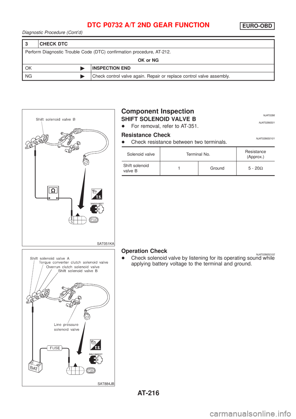
SAT051KA
Component InspectionNJAT0286SHIFT SOLENOID VALVE BNJAT0286S01+For removal, refer to AT-351.
Resistance CheckNJAT0286S0101+Check resistance between two terminals.
Solenoid valve Terminal No.Resistance
(Approx.)
Shift solenoid
valve B1 Ground 5 - 20W
SAT884JB
Operation CheckNJAT0286S0102+Check solenoid valve by listening for its operating sound while
applying battery voltage to the terminal and ground.
DTC P0732 A/T 2ND GEAR FUNCTIONEURO-OBD
Diagnostic Procedure (Cont'd)
AT-216
Page 223 of 2898
Diagnostic ProcedureNJAT0289
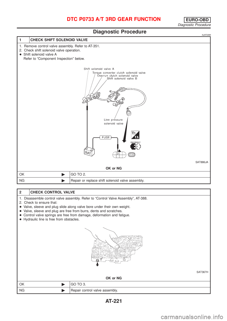
1 CHECK SHIFT SOLENOID VALVE
1. Remove control valve assembly. Refer to AT-351.
2. Check shift solenoid valve operation.
+Shift solenoid valve A
Refer to ªComponent Inspectionº below.
SAT886JA
OK or NG
OK©GO TO 2.
NG©Repair or replace shift solenoid valve assembly.
2 CHECK CONTROL VALVE
1. Disassemble control valve assembly. Refer to ªControl Valve Assemblyº, AT-388.
2. Check to ensure that:
+Valve, sleeve and plug slide along valve bore under their own weight.
+Valve, sleeve and plug are free from burrs, dents and scratches.
+Control valve springs are free from damage, deformation and fatigue.
+Hydraulic line is free from obstacles.
SAT367H
OK or NG
OK©GO TO 3.
NG©Repair control valve assembly.
DTC P0733 A/T 3RD GEAR FUNCTIONEURO-OBD
Diagnostic Procedure
AT-221
Page 224 of 2898
3 CHECK DTC
Perform Diagnostic Trouble Code (DTC) confirmation procedure, AT-218.
OK or NG
OK©INSPECTION END
NG©Check control valve again. Repair or replace control valve assembly.
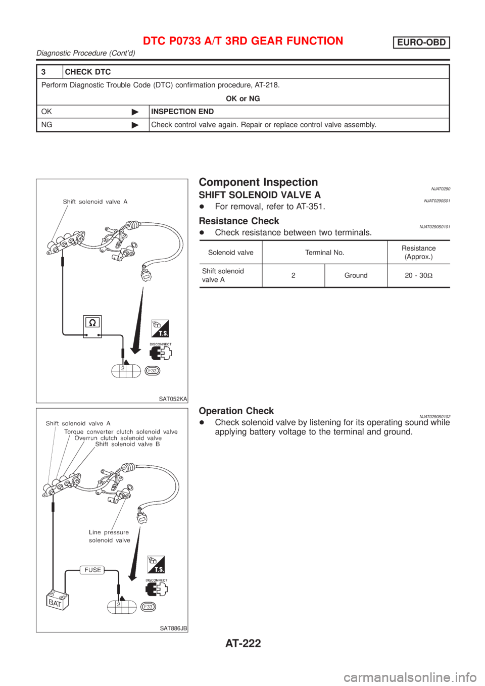
SAT052KA
Component InspectionNJAT0290SHIFT SOLENOID VALVE ANJAT0290S01+For removal, refer to AT-351.
Resistance CheckNJAT0290S0101+Check resistance between two terminals.
Solenoid valve Terminal No.Resistance
(Approx.)
Shift solenoid
valve A2 Ground 20 - 30W
SAT886JB
Operation CheckNJAT0290S0102+Check solenoid valve by listening for its operating sound while
applying battery voltage to the terminal and ground.
DTC P0733 A/T 3RD GEAR FUNCTIONEURO-OBD
Diagnostic Procedure (Cont'd)
AT-222
Page 231 of 2898
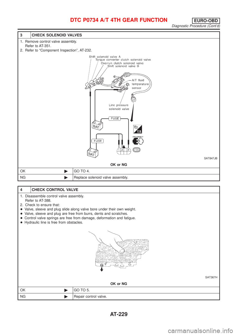
3 CHECK SOLENOID VALVES
1. Remove control valve assembly.
Refer to AT-351.
2. Refer to ªComponent Inspectionº, AT-232.
SAT847JB
OK or NG
OK©GO TO 4.
NG©Replace solenoid valve assembly.
4 CHECK CONTROL VALVE
1. Disassemble control valve assembly.
Refer to AT-388.
2. Check to ensure that:
+Valve, sleeve and plug slide along valve bore under their own weight.
+Valve, sleeve and plug are free from burrs, dents and scratches.
+Control valve springs are free from damage, deformation and fatigue.
+Hydraulic line is free from obstacles.
SAT367H
OK or NG
OK©GO TO 5.
NG©Repair control valve.
DTC P0734 A/T 4TH GEAR FUNCTIONEURO-OBD
Diagnostic Procedure (Cont'd)
AT-229
Page 232 of 2898
5 CHECK SHIFT UP (D3TO D4)
Does A/T shift from D3to D4at the specified speed?
OK or NG
OK©GO TO 9.
NG©Check control valve again. Repair or replace control valve assembly.
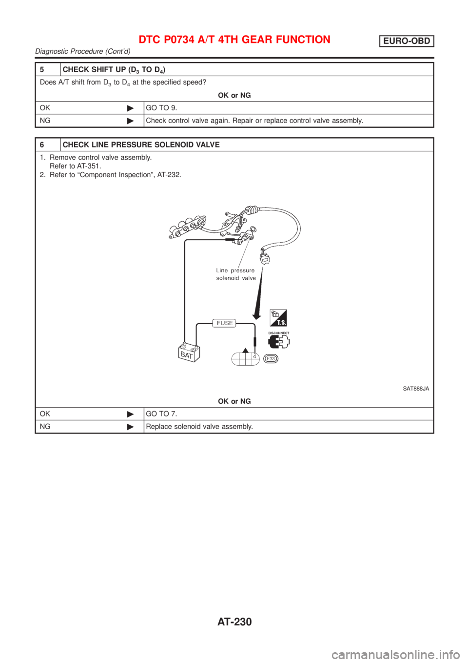
6 CHECK LINE PRESSURE SOLENOID VALVE
1. Remove control valve assembly.
Refer to AT-351.
2. Refer to ªComponent Inspectionº, AT-232.
SAT888JA
OK or NG
OK©GO TO 7.
NG©Replace solenoid valve assembly.
DTC P0734 A/T 4TH GEAR FUNCTIONEURO-OBD
Diagnostic Procedure (Cont'd)
AT-230
Page 233 of 2898
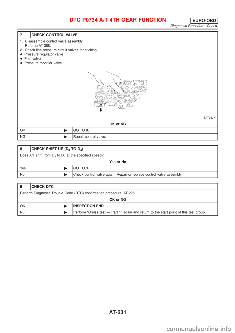
7 CHECK CONTROL VALVE
1. Disassemble control valve assembly.
Refer to AT-388.
2. Check line pressure circuit valves for sticking.
+Pressure regulator valve
+Pilot valve
+Pressure modifier valve
SAT367H
OK or NG
OK©GO TO 8.
NG©Repair control valve.
8 CHECK SHIFT UP (D3TO D4)
Does A/T shift from D3to D4at the specified speed?
YesorNo
Ye s©GO TO 9.
No©Check control valve again. Repair or replace control valve assembly.
9 CHECK DTC
Perform Diagnostic Trouble Code (DTC) confirmation procedure, AT-225.
OK or NG
OK©INSPECTION END
NG©Perform ªCruise test Ð Part 1º again and return to the start point of this test group.
DTC P0734 A/T 4TH GEAR FUNCTIONEURO-OBD
Diagnostic Procedure (Cont'd)
AT-231
Page 238 of 2898
Diagnostic ProcedureNJAT0297
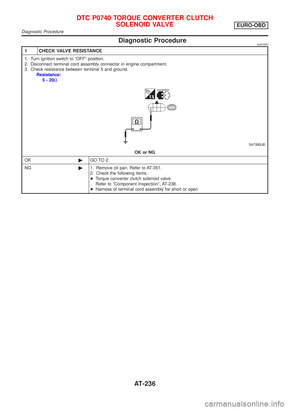
1 CHECK VALVE RESISTANCE
1. Turn ignition switch to ªOFFº position.
2. Disconnect terminal cord assembly connector in engine compartment.
3. Check resistance between terminal 5 and ground.
Resistance:
5-20W
SAT889JB
OK or NG
OK©GO TO 2.
NG©1. Remove oil pan. Refer to AT-351.
2. Check the following items:
+Torque converter clutch solenoid valve
Refer to ªComponent Inspectionº, AT-238.
+Harness of terminal cord assembly for short or open
DTC P0740 TORQUE CONVERTER CLUTCH
SOLENOID VALVE
EURO-OBD
Diagnostic Procedure
AT-236