Assembly NISSAN ALMERA 2001 Repair Manual
[x] Cancel search | Manufacturer: NISSAN, Model Year: 2001, Model line: ALMERA, Model: NISSAN ALMERA 2001Pages: 2898, PDF Size: 60.76 MB
Page 324 of 2898
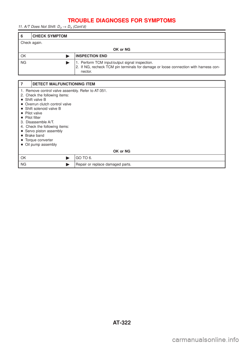
6 CHECK SYMPTOM
Check again.
OK or NG
OK©INSPECTION END
NG©1. Perform TCM input/output signal inspection.
2. If NG, recheck TCM pin terminals for damage or loose connection with harness con-
nector.
7 DETECT MALFUNCTIONING ITEM
1. Remove control valve assembly. Refer to AT-351.
2. Check the following items:
+Shift valve B
+Overrun clutch control valve
+Shift solenoid valve B
+Pilot valve
+Pilot filter
3. Disassemble A/T.
4. Check the following items:
+Servo piston assembly
+Brake band
+Torque converter
+Oil pump assembly
OK or NG
OK©GO TO 6.
NG©Repair or replace damaged parts.
TROUBLE DIAGNOSES FOR SYMPTOMS
11. A/T Does Not Shift: D3®D4(Cont'd)
AT-322
Page 327 of 2898
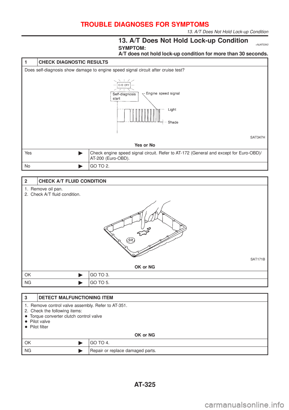
13. A/T Does Not Hold Lock-up Condition=NJAT0343SYMPTOM:
A/T does not hold lock-up condition for more than 30 seconds.
1 CHECK DIAGNOSTIC RESULTS
Does self-diagnosis show damage to engine speed signal circuit after cruise test?
SAT347H
YesorNo
Ye s©Check engine speed signal circuit. Refer to AT-172 (General and except for Euro-OBD)/
AT-200 (Euro-OBD).
No©GO TO 2.
2 CHECK A/T FLUID CONDITION
1. Remove oil pan.
2. Check A/T fluid condition.
SAT171B
OK or NG
OK©GO TO 3.
NG©GO TO 5.
3 DETECT MALFUNCTIONING ITEM
1. Remove control valve assembly. Refer to AT-351.
2. Check the following items:
+Torque converter clutch control valve
+Pilot valve
+Pilot filter
OK or NG
OK©GO TO 4.
NG©Repair or replace damaged parts.
TROUBLE DIAGNOSES FOR SYMPTOMS
13. A/T Does Not Hold Lock-up Condition
AT-325
Page 328 of 2898
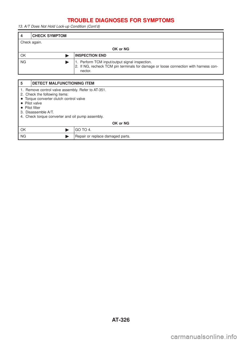
4 CHECK SYMPTOM
Check again.
OK or NG
OK©INSPECTION END
NG©1. Perform TCM input/output signal inspection.
2. If NG, recheck TCM pin terminals for damage or loose connection with harness con-
nector.
5 DETECT MALFUNCTIONING ITEM
1. Remove control valve assembly. Refer to AT-351.
2. Check the following items:
+Torque converter clutch control valve
+Pilot valve
+Pilot filter
3. Disassemble A/T.
4. Check torque converter and oil pump assembly.
OK or NG
OK©GO TO 4.
NG©Repair or replace damaged parts.
TROUBLE DIAGNOSES FOR SYMPTOMS
13. A/T Does Not Hold Lock-up Condition (Cont'd)
AT-326
Page 331 of 2898
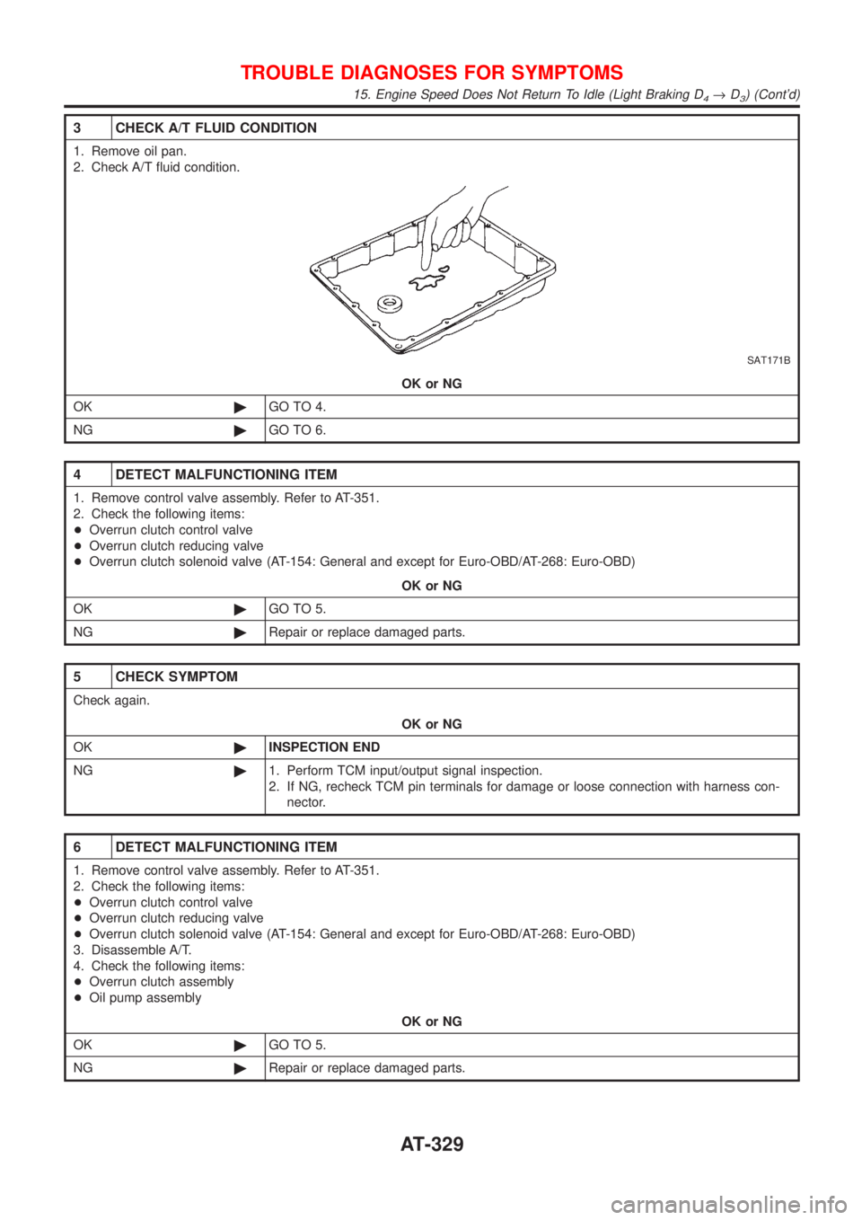
3 CHECK A/T FLUID CONDITION
1. Remove oil pan.
2. Check A/T fluid condition.
SAT171B
OK or NG
OK©GO TO 4.
NG©GO TO 6.
4 DETECT MALFUNCTIONING ITEM
1. Remove control valve assembly. Refer to AT-351.
2. Check the following items:
+Overrun clutch control valve
+Overrun clutch reducing valve
+Overrun clutch solenoid valve (AT-154: General and except for Euro-OBD/AT-268: Euro-OBD)
OK or NG
OK©GO TO 5.
NG©Repair or replace damaged parts.
5 CHECK SYMPTOM
Check again.
OK or NG
OK©INSPECTION END
NG©1. Perform TCM input/output signal inspection.
2. If NG, recheck TCM pin terminals for damage or loose connection with harness con-
nector.
6 DETECT MALFUNCTIONING ITEM
1. Remove control valve assembly. Refer to AT-351.
2. Check the following items:
+Overrun clutch control valve
+Overrun clutch reducing valve
+Overrun clutch solenoid valve (AT-154: General and except for Euro-OBD/AT-268: Euro-OBD)
3. Disassemble A/T.
4. Check the following items:
+Overrun clutch assembly
+Oil pump assembly
OK or NG
OK©GO TO 5.
NG©Repair or replace damaged parts.
TROUBLE DIAGNOSES FOR SYMPTOMS
15. Engine Speed Does Not Return To Idle (Light Braking D4®D3) (Cont'd)
AT-329
Page 336 of 2898
20. Vehicle Does Not Decelerate By Engine
Brake
=NJAT0350SYMPTOM:
Vehicle does not decelerate by engine brake when shifting
from 2
2(12)to11.
1 CHECK SYMPTOM
Is 6. Vehicle Does Not Creep Backward In ªRº Position OK?
YesorNo
Ye s©Go to 15. Engine Speed Does Not Return To Idle (Light Braking D
4®D3), AT-328.
No©Go to 6. Vehicle Does Not Creep Backward In ªRº Position, AT-305.
SAT088JA
SAT360H
SAT004K
21. TCM Self-diagnosis Does Not Activate (PNP,
Overdrive Control and Throttle Position
Switches Circuit Checks)
NJAT0351SYMPTOM:
O/D OFF indicator lamp does not come on in TCM self-diag-
nostic procedure even if the lamp circuit is good.
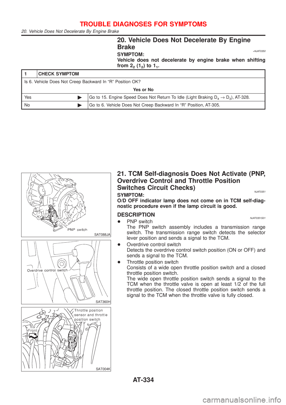
DESCRIPTIONNJAT0351S01+PNP switch
The PNP switch assembly includes a transmission range
switch. The transmission range switch detects the selector
lever position and sends a signal to the TCM.
+Overdrive control switch
Detects the overdrive control switch position (ON or OFF) and
sends a signal to the TCM.
+Throttle position switch
Consists of a wide open throttle position switch and a closed
throttle position switch.
The wide open throttle position switch sends a signal to the
TCM when the throttle valve is open at least 1/2 of the full
throttle position. The closed throttle position switch sends a
signal to the TCM when the throttle valve is fully closed.
TROUBLE DIAGNOSES FOR SYMPTOMS
20. Vehicle Does Not Decelerate By Engine Brake
AT-334
Page 343 of 2898
SAT005K
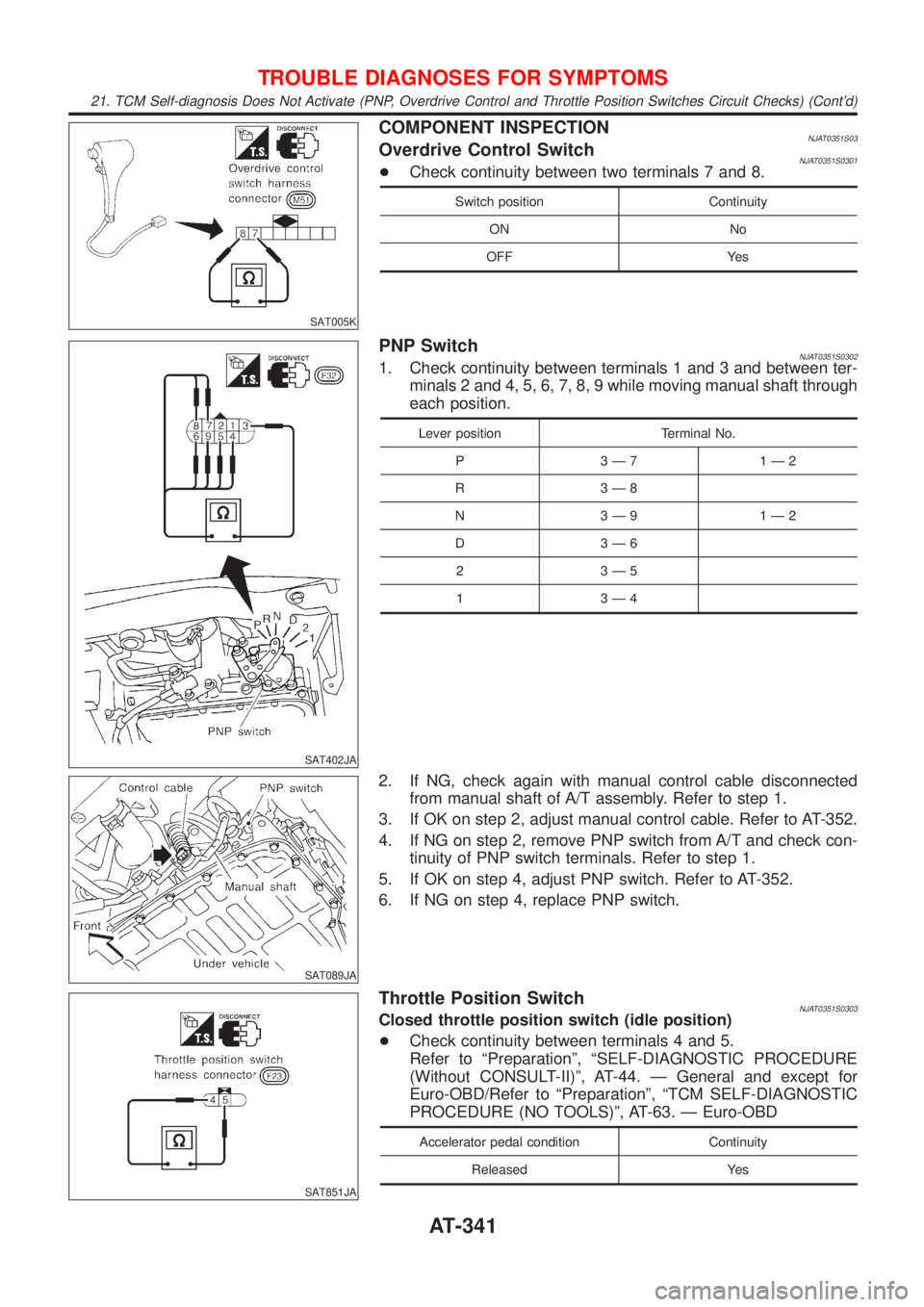
COMPONENT INSPECTIONNJAT0351S03Overdrive Control SwitchNJAT0351S0301+Check continuity between two terminals 7 and 8.
Switch position Continuity
ON No
OFF Yes
SAT402JA
PNP SwitchNJAT0351S03021. Check continuity between terminals 1 and 3 and between ter-
minals 2 and 4, 5, 6, 7, 8, 9 while moving manual shaft through
each position.
Lever position Terminal No.
P 3Ð7 1Ð2
R 3Ð8
N 3Ð9 1Ð2
D 3Ð6
2 3Ð5
1 3Ð4
SAT089JA
2. If NG, check again with manual control cable disconnected
from manual shaft of A/T assembly. Refer to step 1.
3. If OK on step 2, adjust manual control cable. Refer to AT-352.
4. If NG on step 2, remove PNP switch from A/T and check con-
tinuity of PNP switch terminals. Refer to step 1.
5. If OK on step 4, adjust PNP switch. Refer to AT-352.
6. If NG on step 4, replace PNP switch.
SAT851JA
Throttle Position SwitchNJAT0351S0303Closed throttle position switch (idle position)
+Check continuity between terminals 4 and 5.
Refer to ªPreparationº, ªSELF-DIAGNOSTIC PROCEDURE
(Without CONSULT-II)º, AT-44. Ð General and except for
Euro-OBD/Refer to ªPreparationº, ªTCM SELF-DIAGNOSTIC
PROCEDURE (NO TOOLS)º, AT-63. Ð Euro-OBD
Accelerator pedal condition Continuity
Released Yes
TROUBLE DIAGNOSES FOR SYMPTOMS
21. TCM Self-diagnosis Does Not Activate (PNP, Overdrive Control and Throttle Position Switches Circuit Checks) (Cont'd)
AT-341
Page 352 of 2898
SAT854J
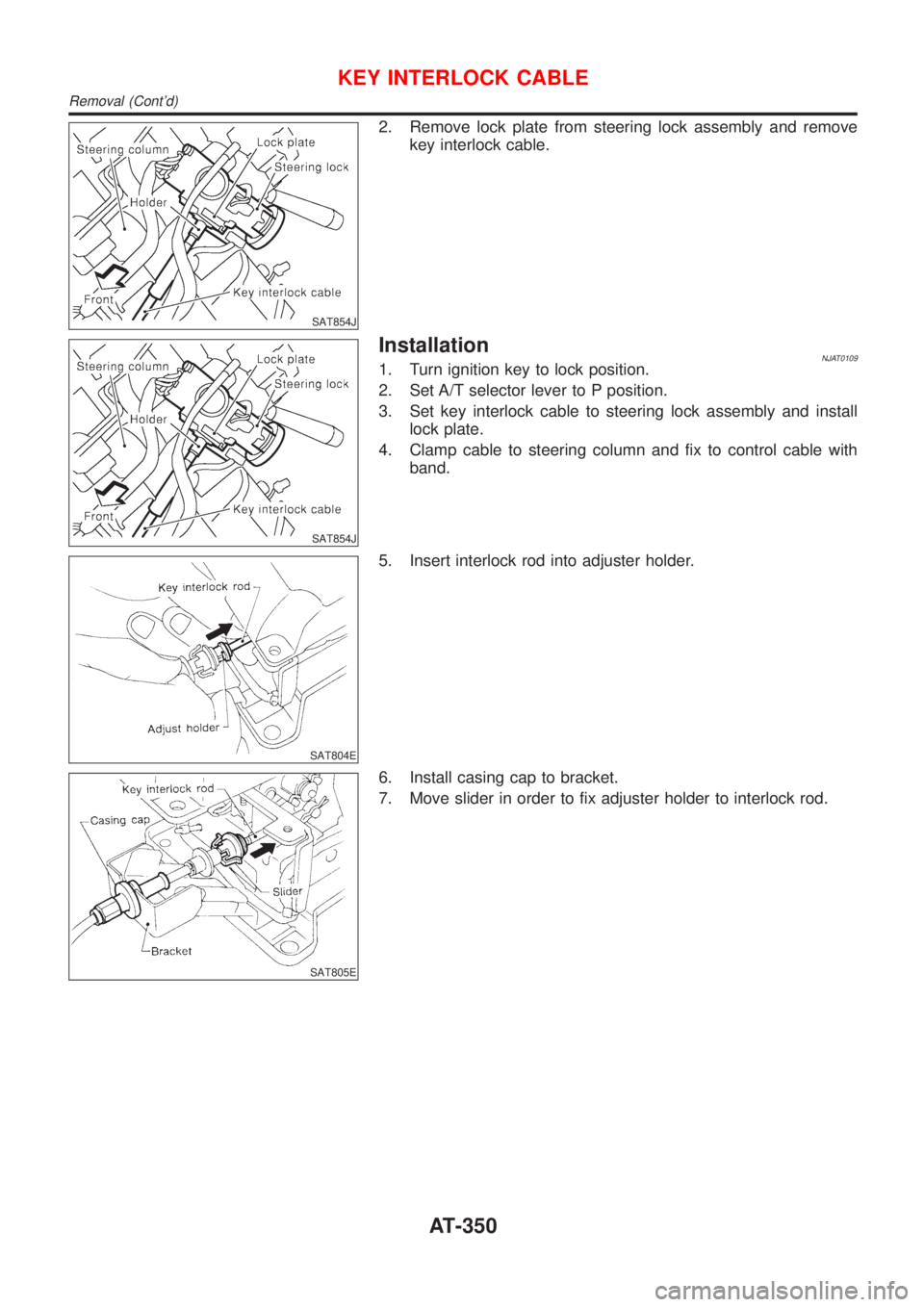
2. Remove lock plate from steering lock assembly and remove
key interlock cable.
SAT854J
InstallationNJAT01091. Turn ignition key to lock position.
2. Set A/T selector lever to P position.
3. Set key interlock cable to steering lock assembly and install
lock plate.
4. Clamp cable to steering column and fix to control cable with
band.
SAT804E
5. Insert interlock rod into adjuster holder.
SAT805E
6. Install casing cap to bracket.
7. Move slider in order to fix adjuster holder to interlock rod.
KEY INTERLOCK CABLE
Removal (Cont'd)
AT-350
Page 353 of 2898
SAT992C
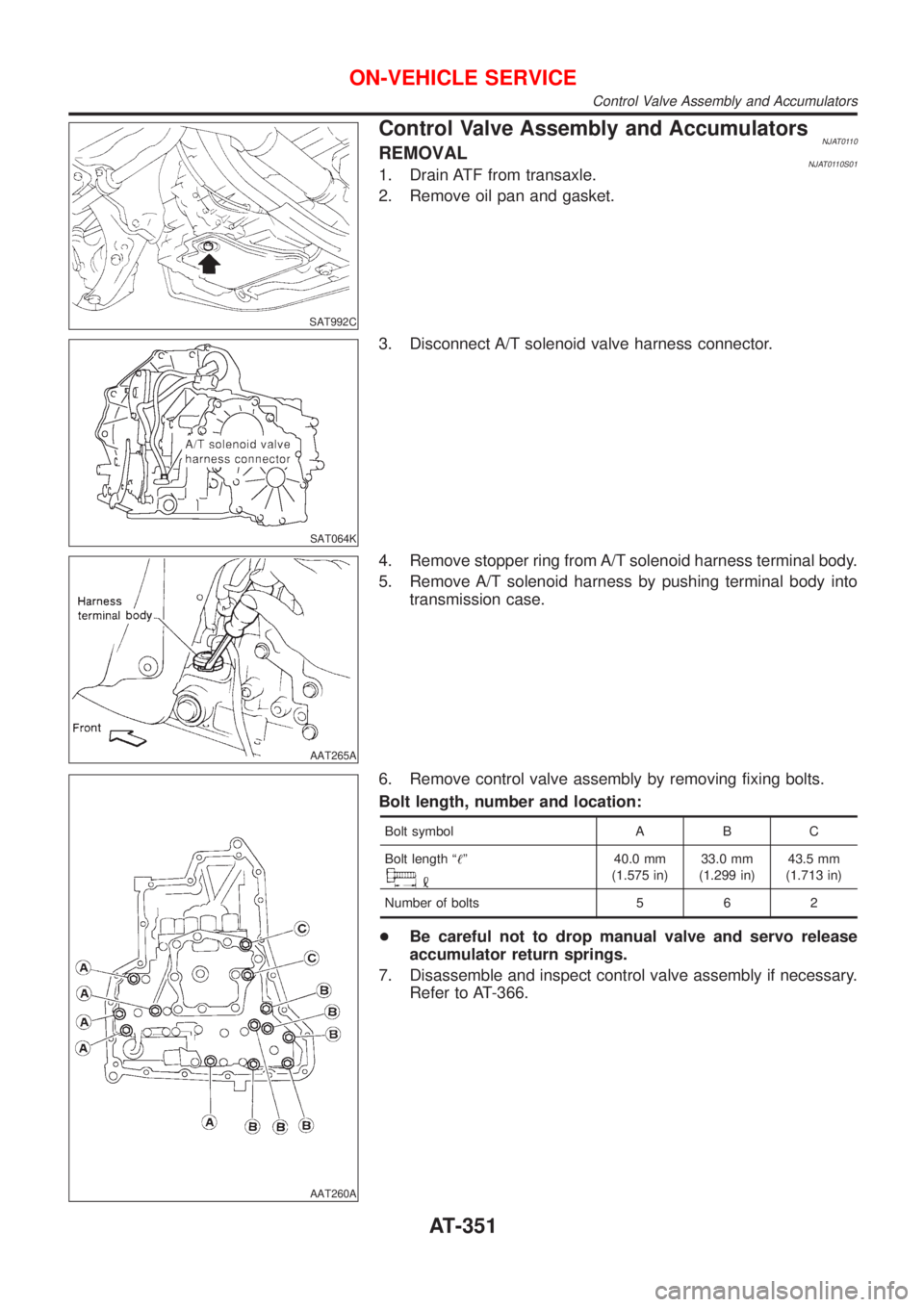
Control Valve Assembly and AccumulatorsNJAT0110REMOVALNJAT0110S011. Drain ATF from transaxle.
2. Remove oil pan and gasket.
SAT064K
3. Disconnect A/T solenoid valve harness connector.
AAT265A
4. Remove stopper ring from A/T solenoid harness terminal body.
5. Remove A/T solenoid harness by pushing terminal body into
transmission case.
AAT260A
6. Remove control valve assembly by removing fixing bolts.
Bolt length, number and location:
Bolt symbol A B C
Bolt length ª!º
40.0 mm
(1.575 in)33.0 mm
(1.299 in)43.5 mm
(1.713 in)
Number of bolts 5 6 2
+Be careful not to drop manual valve and servo release
accumulator return springs.
7. Disassemble and inspect control valve assembly if necessary.
Refer to AT-366.
ON-VEHICLE SERVICE
Control Valve Assembly and Accumulators
AT-351
Page 354 of 2898
SAT935J
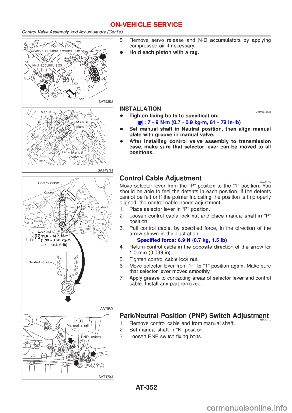
8. Remove servo release and N-D accumulators by applying
compressed air if necessary.
+Hold each piston with a rag.
SAT497H
INSTALLATIONNJAT0110S02+Tighten fixing bolts to specification.
:7-9N´m(0.7 - 0.9 kg-m, 61 - 78 in-lb)
+Set manual shaft in Neutral position, then align manual
plate with groove in manual valve.
+After installing control valve assembly to transmission
case, make sure that selector lever can be moved to all
positions.
AAT980
Control Cable AdjustmentNJAT0111Move selector lever from the ªPº position to the ª1º position. You
should be able to feel the detents in each position. If the detents
cannot be felt or if the pointer indicating the position is improperly
aligned, the control cable needs adjustment.
1. Place selector lever in ªPº position.
2. Loosen control cable lock nut and place manual shaft in ªPº
position.
3. Pull control cable, by specified force, in the direction of the
arrow shown in the illustration.
Specified force: 6.9 N (0.7 kg, 1.5 lb)
4. Return control cable in the opposite direction of the arrow for
1.0 mm (0.039 in).
5. Tighten control cable lock nut.
6. Move selector lever from ªPº to ª1º position again. Make sure
that selector lever moves smoothly.
7. Apply grease to contacting areas of selector lever and control
cable. Install any part removed.
SAT479J
Park/Neutral Position (PNP) Switch AdjustmentNJAT01121. Remove control cable end from manual shaft.
2. Set manual shaft in ªNº position.
3. Loosen PNP switch fixing bolts.
ON-VEHICLE SERVICE
Control Valve Assembly and Accumulators (Cont'd)
AT-352
Page 368 of 2898
NJAT0120
SAT049K
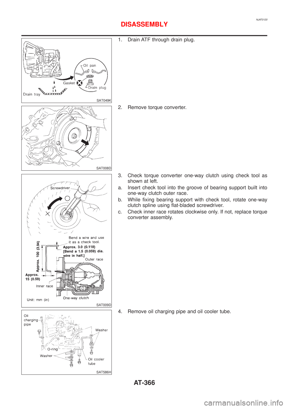
1. Drain ATF through drain plug.
SAT008D
2. Remove torque converter.
SAT009D
3. Check torque converter one-way clutch using check tool as
shown at left.
a. Insert check tool into the groove of bearing support built into
one-way clutch outer race.
b. While fixing bearing support with check tool, rotate one-way
clutch spline using flat-bladed screwdriver.
c. Check inner race rotates clockwise only. If not, replace torque
converter assembly.
SAT586H
4. Remove oil charging pipe and oil cooler tube.
DISASSEMBLY
AT-366