Assembly NISSAN ALMERA 2001 Owner's Manual
[x] Cancel search | Manufacturer: NISSAN, Model Year: 2001, Model line: ALMERA, Model: NISSAN ALMERA 2001Pages: 2898, PDF Size: 60.76 MB
Page 153 of 2898
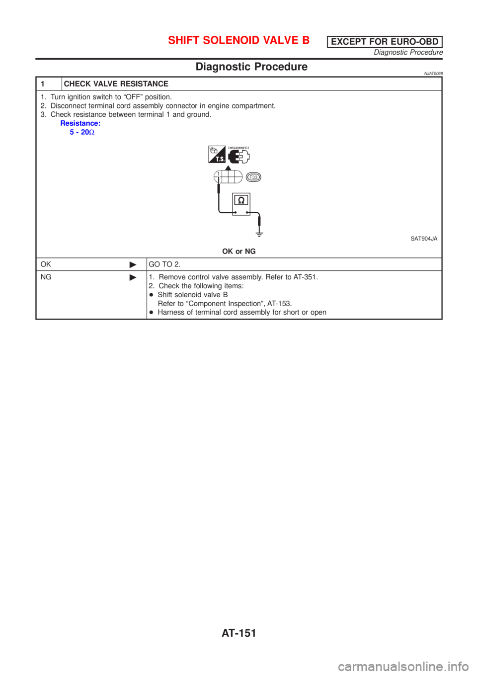
Diagnostic ProcedureNJAT0068
1 CHECK VALVE RESISTANCE
1. Turn ignition switch to ªOFFº position.
2. Disconnect terminal cord assembly connector in engine compartment.
3. Check resistance between terminal 1 and ground.
Resistance:
5-20W
SAT904JA
OK or NG
OK©GO TO 2.
NG©1. Remove control valve assembly. Refer to AT-351.
2. Check the following items:
+Shift solenoid valve B
Refer to ªComponent Inspectionº, AT-153.
+Harness of terminal cord assembly for short or open
SHIFT SOLENOID VALVE BEXCEPT FOR EURO-OBD
Diagnostic Procedure
AT-151
Page 158 of 2898
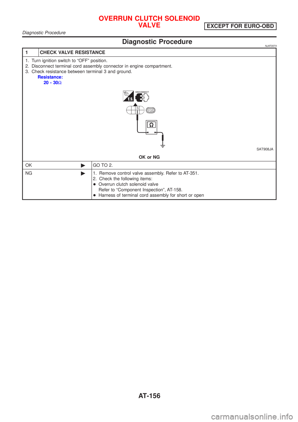
Diagnostic ProcedureNJAT0074
1 CHECK VALVE RESISTANCE
1. Turn ignition switch to ªOFFº position.
2. Disconnect terminal cord assembly connector in engine compartment.
3. Check resistance between terminal 3 and ground.
Resistance:
20-30W
SAT908JA
OK or NG
OK©GO TO 2.
NG©1. Remove control valve assembly. Refer to AT-351.
2. Check the following items:
+Overrun clutch solenoid valve
Refer to ªComponent Inspectionº, AT-158.
+Harness of terminal cord assembly for short or open
OVERRUN CLUTCH SOLENOID
VALVE
EXCEPT FOR EURO-OBD
Diagnostic Procedure
AT-156
Page 164 of 2898
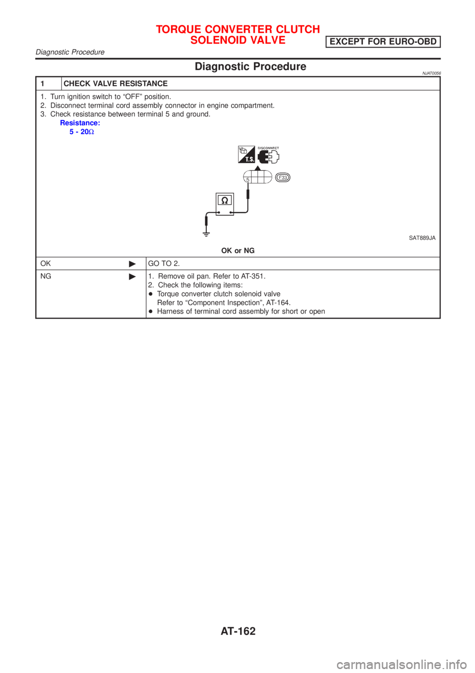
Diagnostic ProcedureNJAT0056
1 CHECK VALVE RESISTANCE
1. Turn ignition switch to ªOFFº position.
2. Disconnect terminal cord assembly connector in engine compartment.
3. Check resistance between terminal 5 and ground.
Resistance:
5-20W
SAT889JA
OK or NG
OK©GO TO 2.
NG©1. Remove oil pan. Refer to AT-351.
2. Check the following items:
+Torque converter clutch solenoid valve
Refer to ªComponent Inspectionº, AT-164.
+Harness of terminal cord assembly for short or open
TORQUE CONVERTER CLUTCH
SOLENOID VALVE
EXCEPT FOR EURO-OBD
Diagnostic Procedure
AT-162
Page 171 of 2898
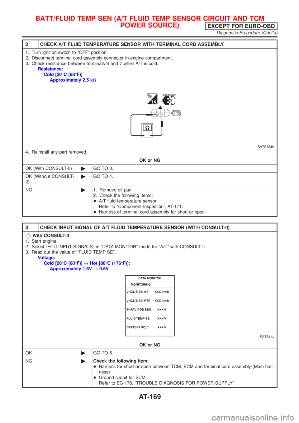
2 CHECK A/T FLUID TEMPERATURE SENSOR WITH TERMINAL CORD ASSEMBLY
1. Turn ignition switch to ªOFFº position.
2. Disconnect terminal cord assembly connector in engine compartment.
3. Check resistance between terminals 6 and 7 when A/T is cold.
Resistance:
Cold [20ÉC (68ÉF)]
Approximately 2.5 kW
SAT912JA
4. Reinstall any part removed.
OK or NG
OK (With CONSULT-II)©GO TO 3.
OK (Without CONSULT-
II)©GO TO 4.
NG©1. Remove oil pan.
2. Check the following items:
+A/T fluid temperature sensor
Refer to ªComponent Inspectionº, AT-171.
+Harness of terminal cord assembly for short or open
3 CHECK INPUT SIGNAL OF A/T FLUID TEMPERATURE SENSOR (WITH CONSULT-II)
With CONSULT-II
1. Start engine.
2. Select ªECU INPUT SIGNALSº in ªDATA MONITORº mode for ªA/Tº with CONSULT-II.
3. Read out the value of ªFLUID TEMP SEº.
Voltage:
Cold [20ÉC (68ÉF)]®Hot [80ÉC (176ÉF)]:
Approximately 1.5V®0.5V
SAT614J
OK or NG
OK©GO TO 5.
NG©Check the following item:
+Harness for short or open between TCM, ECM and terminal cord assembly (Main har-
ness)
+Ground circuit for ECM
Refer to EC-178, ªTROUBLE DIAGNOSIS FOR POWER SUPPLYº.
BATT/FLUID TEMP SEN (A/T FLUID TEMP SENSOR CIRCUIT AND TCM
POWER SOURCE)
EXCEPT FOR EURO-OBD
Diagnostic Procedure (Cont'd)
AT-169
Page 172 of 2898
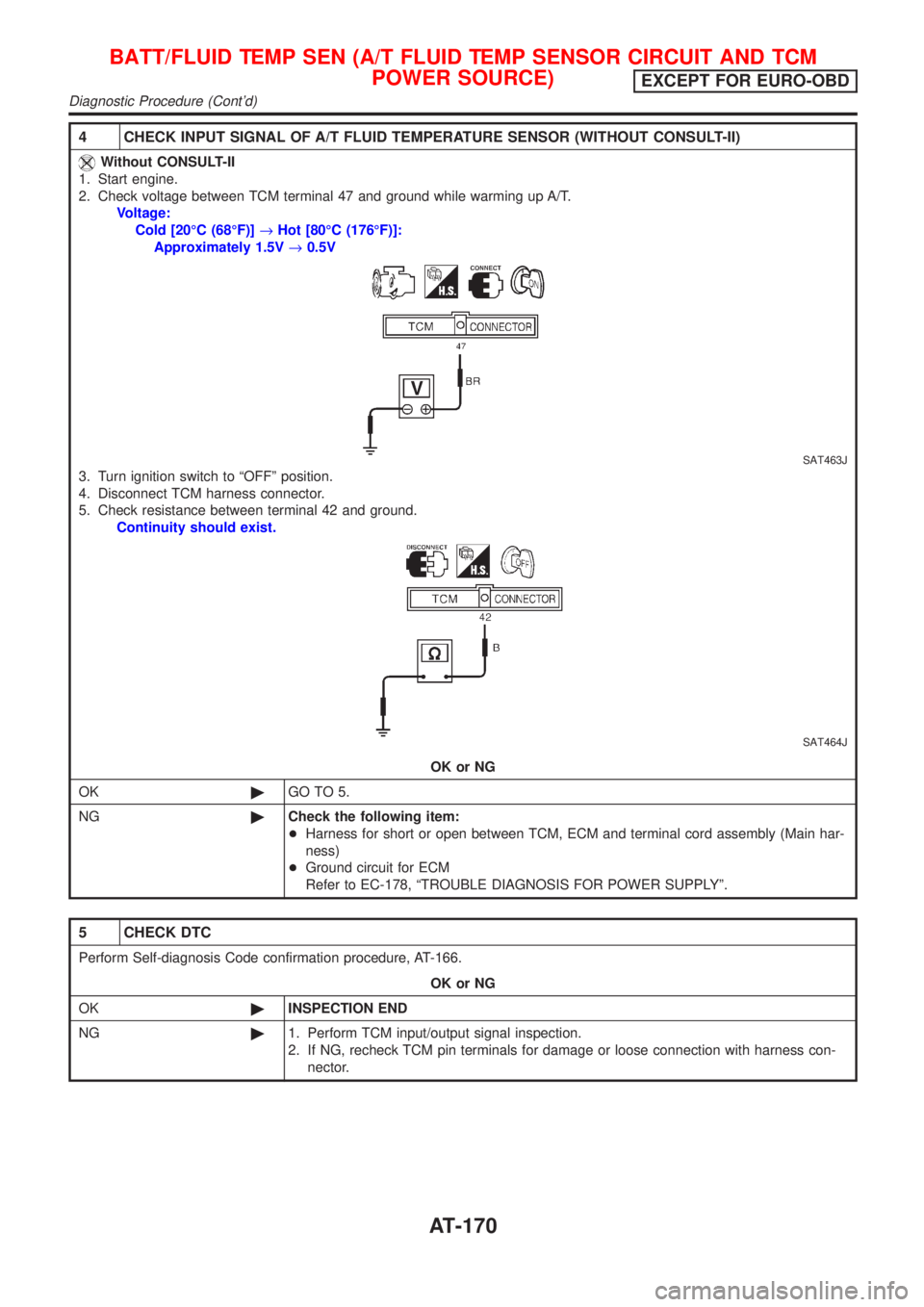
4 CHECK INPUT SIGNAL OF A/T FLUID TEMPERATURE SENSOR (WITHOUT CONSULT-II)
Without CONSULT-II
1. Start engine.
2. Check voltage between TCM terminal 47 and ground while warming up A/T.
Voltage:
Cold [20ÉC (68ÉF)]®Hot [80ÉC (176ÉF)]:
Approximately 1.5V®0.5V
SAT463J
3. Turn ignition switch to ªOFFº position.
4. Disconnect TCM harness connector.
5. Check resistance between terminal 42 and ground.
Continuity should exist.
SAT464J
OK or NG
OK©GO TO 5.
NG©Check the following item:
+Harness for short or open between TCM, ECM and terminal cord assembly (Main har-
ness)
+Ground circuit for ECM
Refer to EC-178, ªTROUBLE DIAGNOSIS FOR POWER SUPPLYº.
5 CHECK DTC
Perform Self-diagnosis Code confirmation procedure, AT-166.
OK or NG
OK©INSPECTION END
NG©1. Perform TCM input/output signal inspection.
2. If NG, recheck TCM pin terminals for damage or loose connection with harness con-
nector.
BATT/FLUID TEMP SEN (A/T FLUID TEMP SENSOR CIRCUIT AND TCM
POWER SOURCE)
EXCEPT FOR EURO-OBD
Diagnostic Procedure (Cont'd)
AT-170
Page 181 of 2898
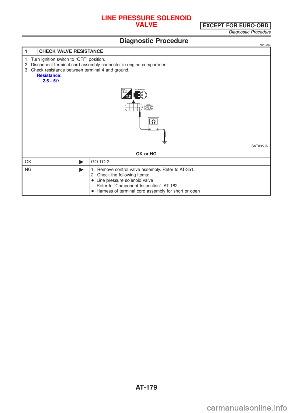
Diagnostic ProcedureNJAT0062
1 CHECK VALVE RESISTANCE
1. Turn ignition switch to ªOFFº position.
2. Disconnect terminal cord assembly connector in engine compartment.
3. Check resistance between terminal 4 and ground.
Resistance:
2.5-5W
SAT895JA
OK or NG
OK©GO TO 2.
NG©1. Remove control valve assembly. Refer to AT-351.
2. Check the following items:
+Line pressure solenoid valve
Refer to ªComponent Inspectionº, AT-182.
+Harness of terminal cord assembly for short or open
LINE PRESSURE SOLENOID
VALVE
EXCEPT FOR EURO-OBD
Diagnostic Procedure
AT-179
Page 182 of 2898
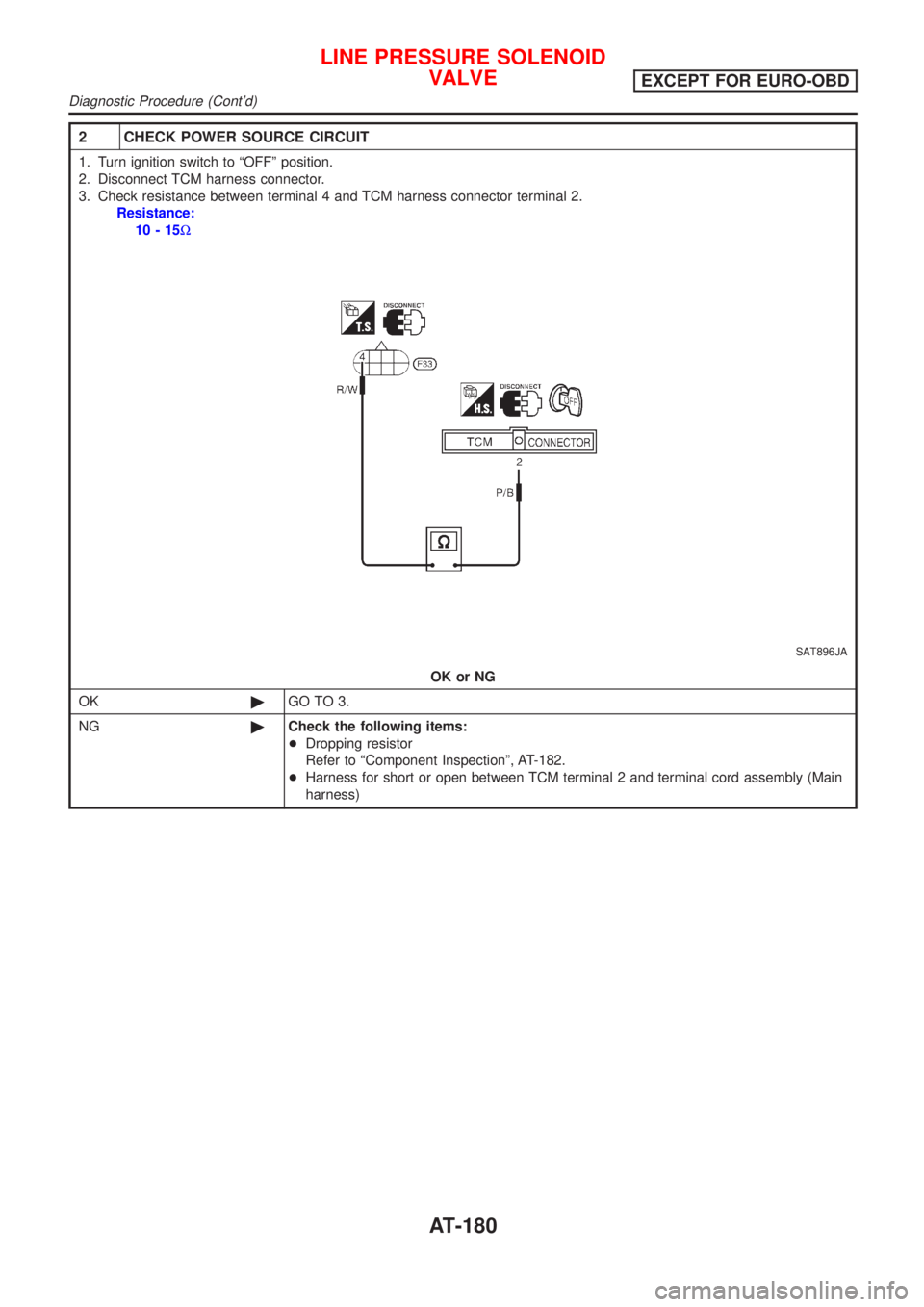
2 CHECK POWER SOURCE CIRCUIT
1. Turn ignition switch to ªOFFº position.
2. Disconnect TCM harness connector.
3. Check resistance between terminal 4 and TCM harness connector terminal 2.
Resistance:
10-15W
SAT896JA
OK or NG
OK©GO TO 3.
NG©Check the following items:
+Dropping resistor
Refer to ªComponent Inspectionº, AT-182.
+Harness for short or open between TCM terminal 2 and terminal cord assembly (Main
harness)
LINE PRESSURE SOLENOID
VALVE
EXCEPT FOR EURO-OBD
Diagnostic Procedure (Cont'd)
AT-180
Page 185 of 2898
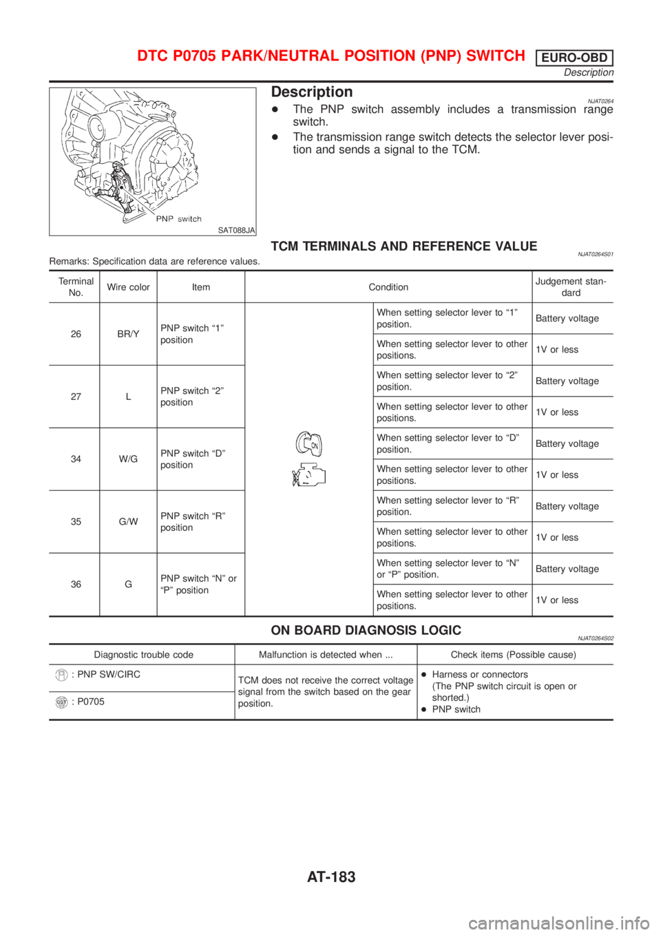
SAT088JA
DescriptionNJAT0264+The PNP switch assembly includes a transmission range
switch.
+The transmission range switch detects the selector lever posi-
tion and sends a signal to the TCM.
TCM TERMINALS AND REFERENCE VALUENJAT0264S01Remarks: Specification data are reference values.
Terminal
No.Wire color Item ConditionJudgement stan-
dard
26 BR/YPNP switch ª1º
position
When setting selector lever to ª1º
position.Battery voltage
When setting selector lever to other
positions.1V or less
27 LPNP switch ª2º
positionWhen setting selector lever to ª2º
position.Battery voltage
When setting selector lever to other
positions.1V or less
34 W/GPNP switch ªDº
positionWhen setting selector lever to ªDº
position.Battery voltage
When setting selector lever to other
positions.1V or less
35 G/WPNP switch ªRº
positionWhen setting selector lever to ªRº
position.Battery voltage
When setting selector lever to other
positions.1V or less
36 GPNP switch ªNº or
ªPº positionWhen setting selector lever to ªNº
or ªPº position.Battery voltage
When setting selector lever to other
positions.1V or less
ON BOARD DIAGNOSIS LOGICNJAT0264S02
Diagnostic trouble code Malfunction is detected when ... Check items (Possible cause)
: PNP SW/CIRC
TCM does not receive the correct voltage
signal from the switch based on the gear
position.+Harness or connectors
(The PNP switch circuit is open or
shorted.)
+PNP switch
: P0705
DTC P0705 PARK/NEUTRAL POSITION (PNP) SWITCHEURO-OBD
Description
AT-183
Page 190 of 2898
3 CHECK DTC
Perform Diagnostic Trouble Code (DTC) confirmation procedure, AT-184.
OK or NG
OK©INSPECTION END
NG©1. Perform TCM input/output signal inspection.
2. If NG, recheck TCM pin terminals for damage or loose connection with harness con-
nector.
SAT402JB
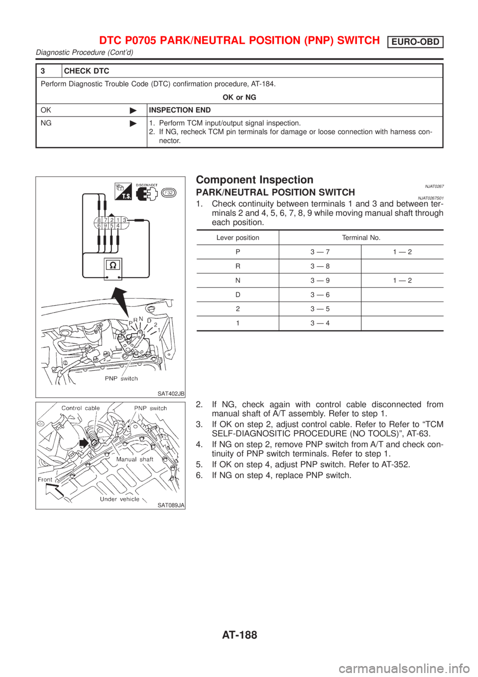
Component InspectionNJAT0267PARK/NEUTRAL POSITION SWITCHNJAT0267S011. Check continuity between terminals 1 and 3 and between ter-
minals 2 and 4, 5, 6, 7, 8, 9 while moving manual shaft through
each position.
Lever position Terminal No.
P 3Ð7 1Ð2
R 3Ð8
N 3Ð9 1Ð2
D 3Ð6
2 3Ð5
1 3Ð4
SAT089JA
2. If NG, check again with control cable disconnected from
manual shaft of A/T assembly. Refer to step 1.
3. If OK on step 2, adjust control cable. Refer to Refer to ªTCM
SELF-DIAGNOSITIC PROCEDURE (NO TOOLS)º, AT-63.
4. If NG on step 2, remove PNP switch from A/T and check con-
tinuity of PNP switch terminals. Refer to step 1.
5. If OK on step 4, adjust PNP switch. Refer to AT-352.
6. If NG on step 4, replace PNP switch.
DTC P0705 PARK/NEUTRAL POSITION (PNP) SWITCHEURO-OBD
Diagnostic Procedure (Cont'd)
AT-188
Page 196 of 2898
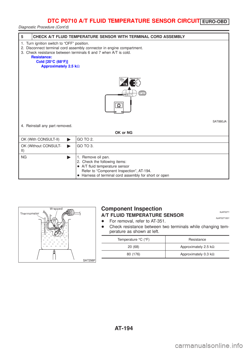
5 CHECK A/T FLUID TEMPERATURE SENSOR WITH TERMINAL CORD ASSEMBLY
1. Turn ignition switch to ªOFFº position.
2. Disconnect terminal cord assembly connector in engine compartment.
3. Check resistance between terminals 6 and 7 when A/T is cold.
Resistance:
Cold [20ÉC (68ÉF)]
Approximately 2.5 kW
SAT880JA
4. Reinstall any part removed.
OK or NG
OK (With CONSULT-II)©GO TO 2.
OK (Without CONSULT-
II)©GO TO 3.
NG©1. Remove oil pan.
2. Check the following items:
+A/T fluid temperature sensor
Refer to ªComponent Inspectionº, AT-194.
+Harness of terminal cord assembly for short or open
SAT298F
Component InspectionNJAT0271A/T FLUID TEMPERATURE SENSORNJAT0271S01+For removal, refer to AT-351.
+Check resistance between two terminals while changing tem-
perature as shown at left.
Temperature ÉC (ÉF) Resistance
20 (68) Approximately 2.5 kW
80 (176) Approximately 0.3 kW
DTC P0710 A/T FLUID TEMPERATURE SENSOR CIRCUITEURO-OBD
Diagnostic Procedure (Cont'd)
AT-194