check oil NISSAN ALMERA 2001 Owner's Guide
[x] Cancel search | Manufacturer: NISSAN, Model Year: 2001, Model line: ALMERA, Model: NISSAN ALMERA 2001Pages: 2898, PDF Size: 60.76 MB
Page 324 of 2898
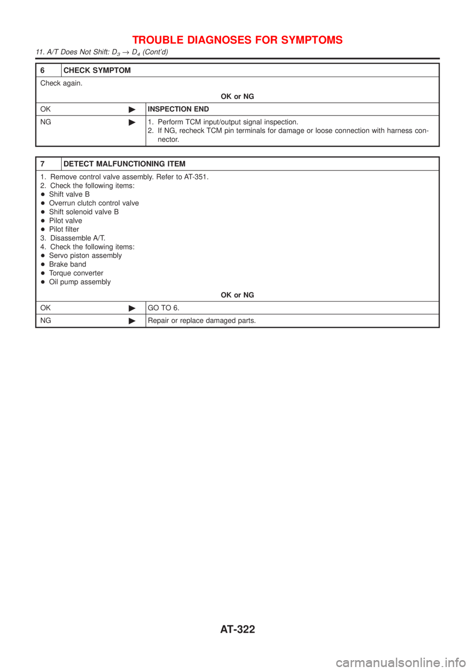
6 CHECK SYMPTOM
Check again.
OK or NG
OK©INSPECTION END
NG©1. Perform TCM input/output signal inspection.
2. If NG, recheck TCM pin terminals for damage or loose connection with harness con-
nector.
7 DETECT MALFUNCTIONING ITEM
1. Remove control valve assembly. Refer to AT-351.
2. Check the following items:
+Shift valve B
+Overrun clutch control valve
+Shift solenoid valve B
+Pilot valve
+Pilot filter
3. Disassemble A/T.
4. Check the following items:
+Servo piston assembly
+Brake band
+Torque converter
+Oil pump assembly
OK or NG
OK©GO TO 6.
NG©Repair or replace damaged parts.
TROUBLE DIAGNOSES FOR SYMPTOMS
11. A/T Does Not Shift: D3®D4(Cont'd)
AT-322
Page 327 of 2898
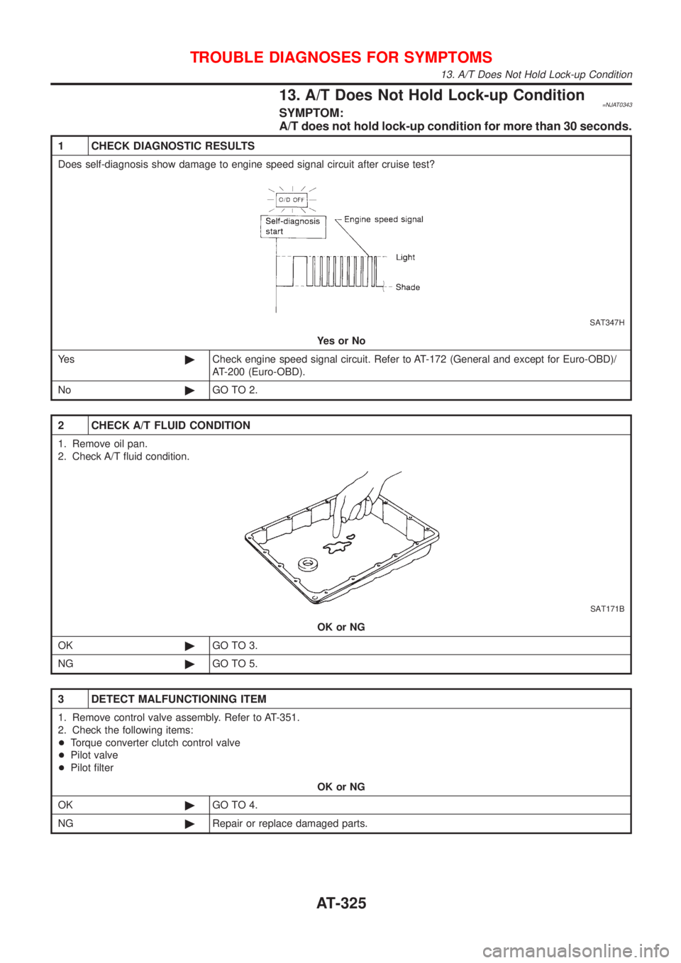
13. A/T Does Not Hold Lock-up Condition=NJAT0343SYMPTOM:
A/T does not hold lock-up condition for more than 30 seconds.
1 CHECK DIAGNOSTIC RESULTS
Does self-diagnosis show damage to engine speed signal circuit after cruise test?
SAT347H
YesorNo
Ye s©Check engine speed signal circuit. Refer to AT-172 (General and except for Euro-OBD)/
AT-200 (Euro-OBD).
No©GO TO 2.
2 CHECK A/T FLUID CONDITION
1. Remove oil pan.
2. Check A/T fluid condition.
SAT171B
OK or NG
OK©GO TO 3.
NG©GO TO 5.
3 DETECT MALFUNCTIONING ITEM
1. Remove control valve assembly. Refer to AT-351.
2. Check the following items:
+Torque converter clutch control valve
+Pilot valve
+Pilot filter
OK or NG
OK©GO TO 4.
NG©Repair or replace damaged parts.
TROUBLE DIAGNOSES FOR SYMPTOMS
13. A/T Does Not Hold Lock-up Condition
AT-325
Page 328 of 2898
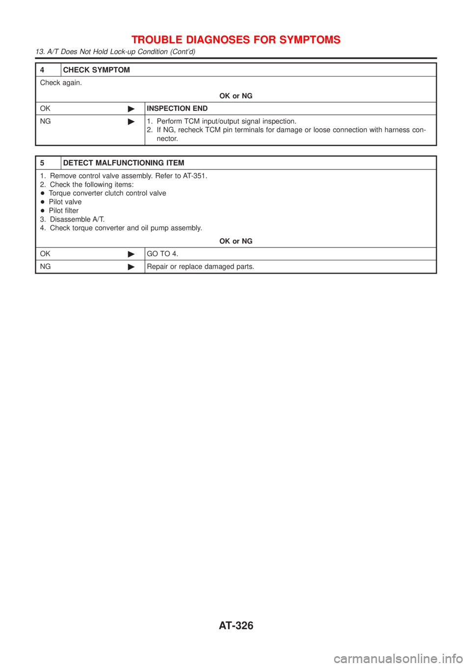
4 CHECK SYMPTOM
Check again.
OK or NG
OK©INSPECTION END
NG©1. Perform TCM input/output signal inspection.
2. If NG, recheck TCM pin terminals for damage or loose connection with harness con-
nector.
5 DETECT MALFUNCTIONING ITEM
1. Remove control valve assembly. Refer to AT-351.
2. Check the following items:
+Torque converter clutch control valve
+Pilot valve
+Pilot filter
3. Disassemble A/T.
4. Check torque converter and oil pump assembly.
OK or NG
OK©GO TO 4.
NG©Repair or replace damaged parts.
TROUBLE DIAGNOSES FOR SYMPTOMS
13. A/T Does Not Hold Lock-up Condition (Cont'd)
AT-326
Page 331 of 2898
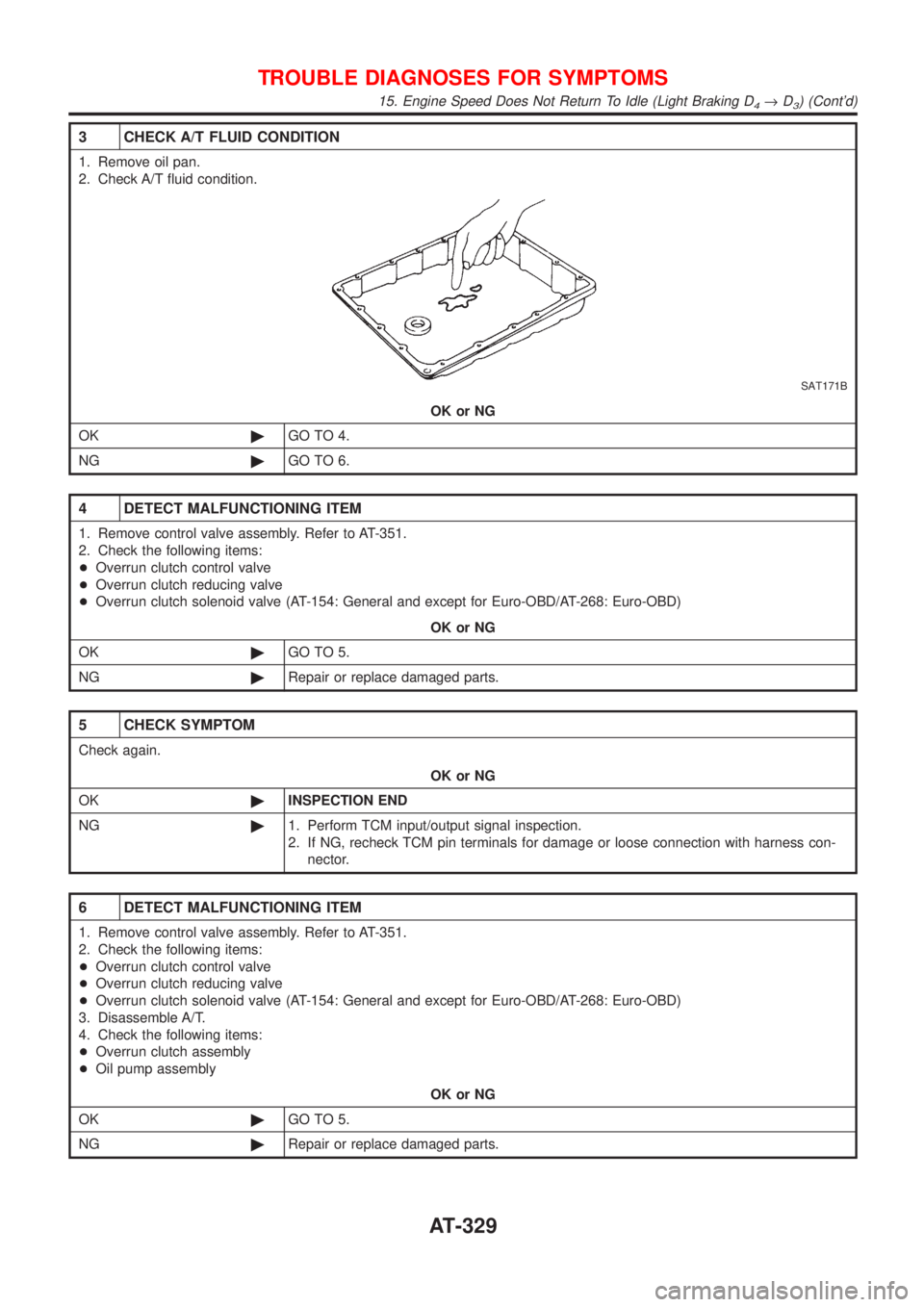
3 CHECK A/T FLUID CONDITION
1. Remove oil pan.
2. Check A/T fluid condition.
SAT171B
OK or NG
OK©GO TO 4.
NG©GO TO 6.
4 DETECT MALFUNCTIONING ITEM
1. Remove control valve assembly. Refer to AT-351.
2. Check the following items:
+Overrun clutch control valve
+Overrun clutch reducing valve
+Overrun clutch solenoid valve (AT-154: General and except for Euro-OBD/AT-268: Euro-OBD)
OK or NG
OK©GO TO 5.
NG©Repair or replace damaged parts.
5 CHECK SYMPTOM
Check again.
OK or NG
OK©INSPECTION END
NG©1. Perform TCM input/output signal inspection.
2. If NG, recheck TCM pin terminals for damage or loose connection with harness con-
nector.
6 DETECT MALFUNCTIONING ITEM
1. Remove control valve assembly. Refer to AT-351.
2. Check the following items:
+Overrun clutch control valve
+Overrun clutch reducing valve
+Overrun clutch solenoid valve (AT-154: General and except for Euro-OBD/AT-268: Euro-OBD)
3. Disassemble A/T.
4. Check the following items:
+Overrun clutch assembly
+Oil pump assembly
OK or NG
OK©GO TO 5.
NG©Repair or replace damaged parts.
TROUBLE DIAGNOSES FOR SYMPTOMS
15. Engine Speed Does Not Return To Idle (Light Braking D4®D3) (Cont'd)
AT-329
Page 355 of 2898
SAT480J
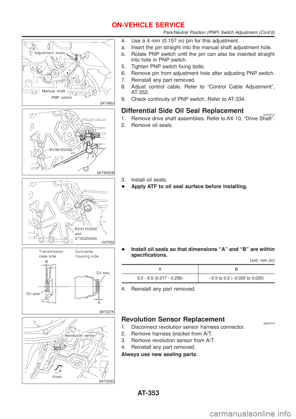
4. Usea4mm(0.157 in) pin for this adjustment.
a. Insert the pin straight into the manual shaft adjustment hole.
b. Rotate PNP switch until the pin can also be inserted straight
into hole in PNP switch.
5. Tighten PNP switch fixing bolts.
6. Remove pin from adjustment hole after adjusting PNP switch.
7. Reinstall any part removed.
8. Adjust control cable. Refer to ªControl Cable Adjustmentº,
AT-352.
9. Check continuity of PNP switch. Refer to AT-334.
SAT905DB
Differential Side Oil Seal ReplacementNJAT01131. Remove drive shaft assemblies. Refer to AX-10, ªDrive Shaftº.
2. Remove oil seals.
XAT002
3. Install oil seals.
+Apply ATF to oil seal surface before installing.
SAT027K
+Install oil seals so that dimensions ªAº and ªBº are within
specifications.
Unit: mm (in)
AB
5.5 - 6.5 (0.217 - 0.256) þ0.5 to 0.5 (þ0.020 to 0.020)
4. Reinstall any part removed.
SAT303G
Revolution Sensor ReplacementNJAT01141. Disconnect revolution sensor harness connector.
2. Remove harness bracket from A/T.
3. Remove revolution sensor from A/T.
4. Reinstall any part removed.
Always use new sealing parts.
ON-VEHICLE SERVICE
Park/Neutral Position (PNP) Switch Adjustment (Cont'd)
AT-353
Page 368 of 2898
NJAT0120
SAT049K
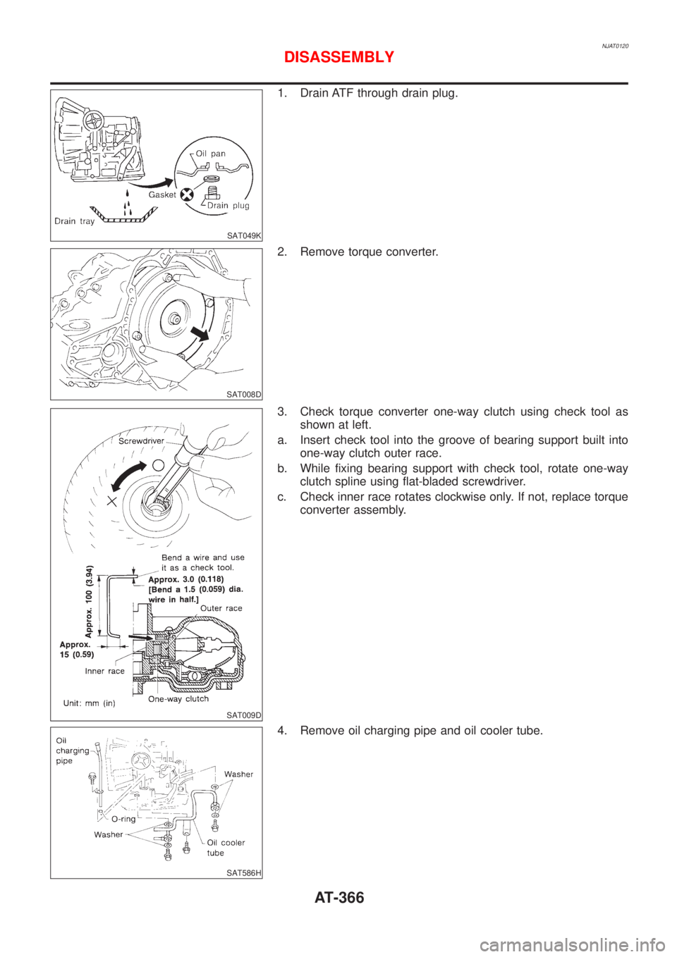
1. Drain ATF through drain plug.
SAT008D
2. Remove torque converter.
SAT009D
3. Check torque converter one-way clutch using check tool as
shown at left.
a. Insert check tool into the groove of bearing support built into
one-way clutch outer race.
b. While fixing bearing support with check tool, rotate one-way
clutch spline using flat-bladed screwdriver.
c. Check inner race rotates clockwise only. If not, replace torque
converter assembly.
SAT586H
4. Remove oil charging pipe and oil cooler tube.
DISASSEMBLY
AT-366
Page 369 of 2898
SAT023JB
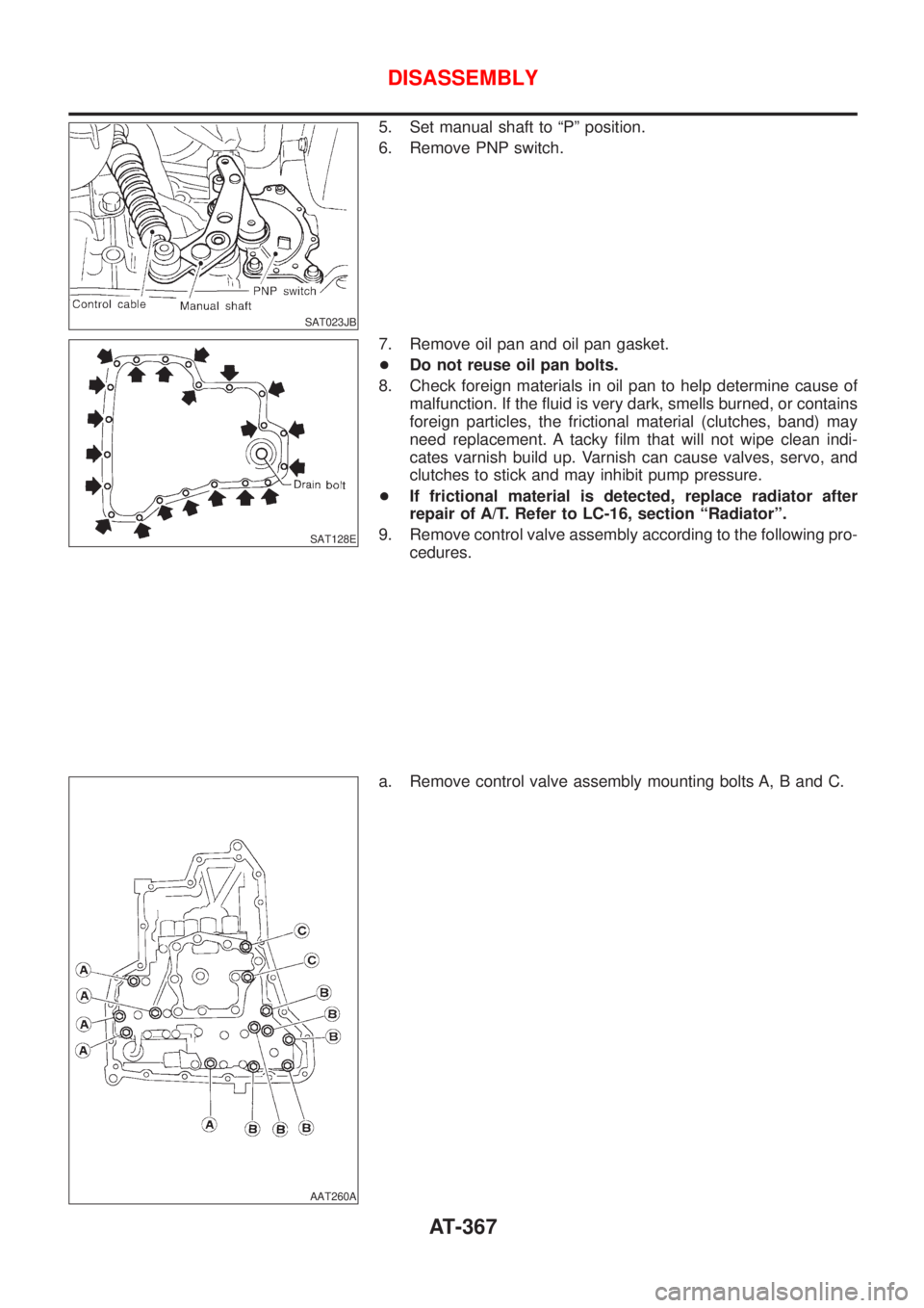
5. Set manual shaft to ªPº position.
6. Remove PNP switch.
SAT128E
7. Remove oil pan and oil pan gasket.
+Do not reuse oil pan bolts.
8. Check foreign materials in oil pan to help determine cause of
malfunction. If the fluid is very dark, smells burned, or contains
foreign particles, the frictional material (clutches, band) may
need replacement. A tacky film that will not wipe clean indi-
cates varnish build up. Varnish can cause valves, servo, and
clutches to stick and may inhibit pump pressure.
+If frictional material is detected, replace radiator after
repair of A/T. Refer to LC-16, section ªRadiatorº.
9. Remove control valve assembly according to the following pro-
cedures.
AAT260A
a. Remove control valve assembly mounting bolts A, B and C.
DISASSEMBLY
AT-367
Page 371 of 2898
SAT023DA
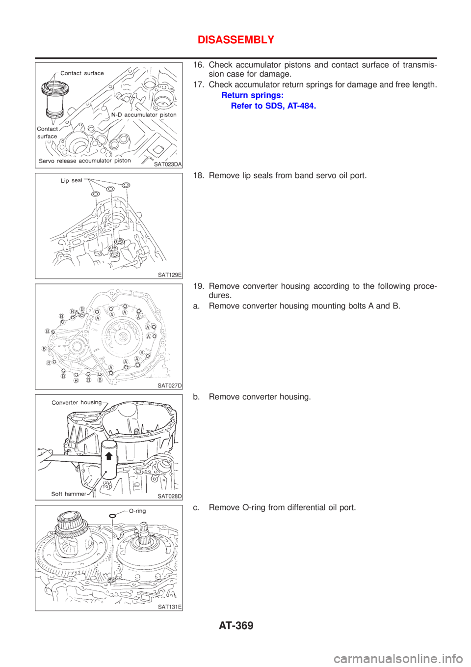
16. Check accumulator pistons and contact surface of transmis-
sion case for damage.
17. Check accumulator return springs for damage and free length.
Return springs:
Refer to SDS, AT-484.
SAT129E
18. Remove lip seals from band servo oil port.
SAT027D
19. Remove converter housing according to the following proce-
dures.
a. Remove converter housing mounting bolts A and B.
SAT028D
b. Remove converter housing.
SAT131E
c. Remove O-ring from differential oil port.
DISASSEMBLY
AT-369
Page 384 of 2898
SAT049F
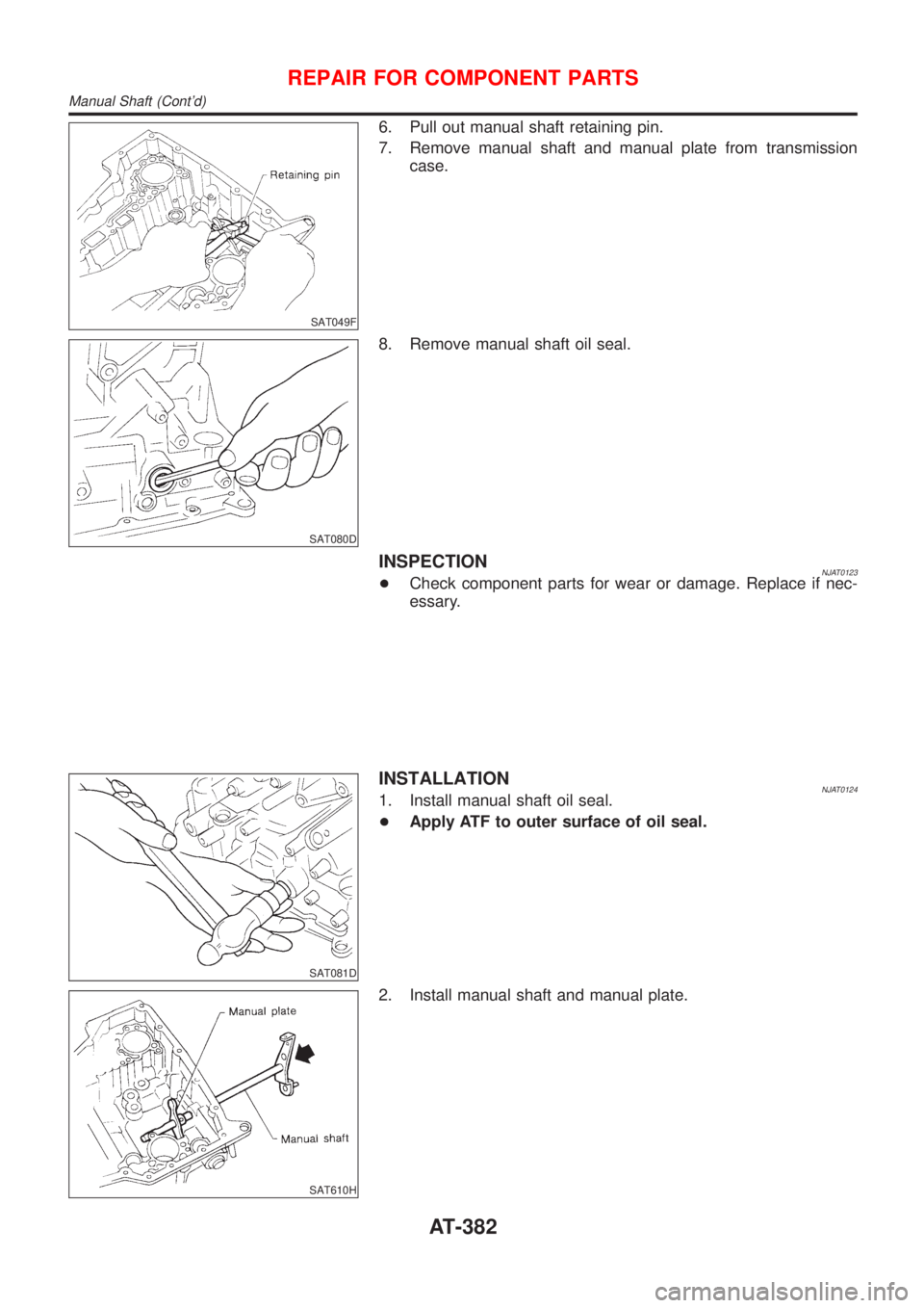
6. Pull out manual shaft retaining pin.
7. Remove manual shaft and manual plate from transmission
case.
SAT080D
8. Remove manual shaft oil seal.
INSPECTIONNJAT0123+Check component parts for wear or damage. Replace if nec-
essary.
SAT081D
INSTALLATIONNJAT01241. Install manual shaft oil seal.
+Apply ATF to outer surface of oil seal.
SAT610H
2. Install manual shaft and manual plate.
REPAIR FOR COMPONENT PARTS
Manual Shaft (Cont'd)
AT-382
Page 387 of 2898
SAT093D
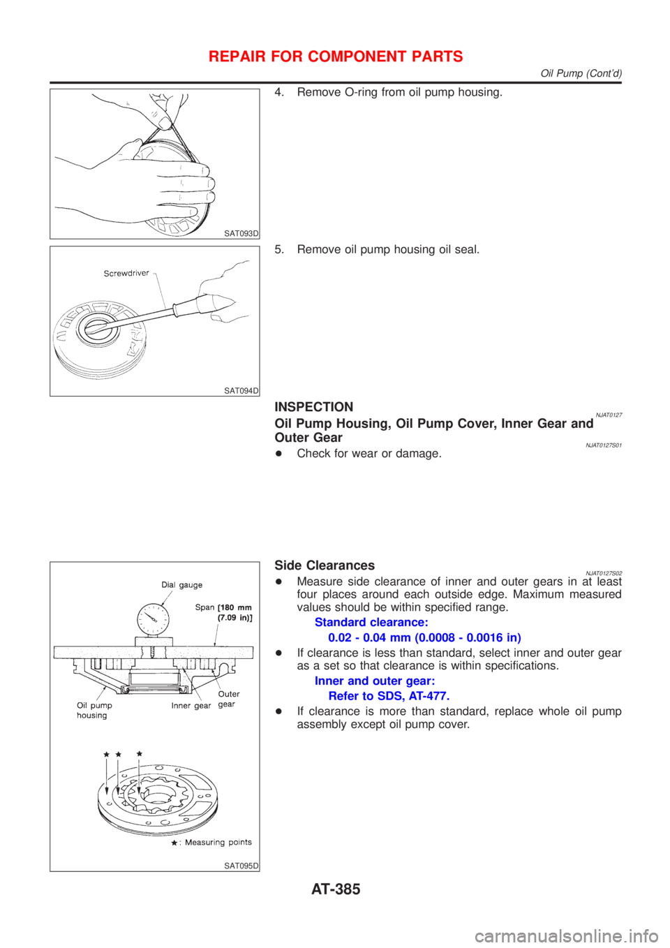
4. Remove O-ring from oil pump housing.
SAT094D
5. Remove oil pump housing oil seal.
INSPECTIONNJAT0127Oil Pump Housing, Oil Pump Cover, Inner Gear and
Outer Gear
NJAT0127S01+Check for wear or damage.
SAT095D
Side ClearancesNJAT0127S02+Measure side clearance of inner and outer gears in at least
four places around each outside edge. Maximum measured
values should be within specified range.
Standard clearance:
0.02 - 0.04 mm (0.0008 - 0.0016 in)
+If clearance is less than standard, select inner and outer gear
as a set so that clearance is within specifications.
Inner and outer gear:
Refer to SDS, AT-477.
+If clearance is more than standard, replace whole oil pump
assembly except oil pump cover.
REPAIR FOR COMPONENT PARTS
Oil Pump (Cont'd)
AT-385