lock NISSAN ALMERA 2001 Service Manual
[x] Cancel search | Manufacturer: NISSAN, Model Year: 2001, Model line: ALMERA, Model: NISSAN ALMERA 2001Pages: 2898, PDF Size: 60.76 MB
Page 2742 of 2898

SRS822
INSTALLATIONNJRS00541. Set the front wheels in the straight-ahead position.
2. Make sure that the spiral cable is in the neutral position.
The neutral position is detected by turning left about 3.5 revo-
lutions from the right end position. Align the two marks (
).
CAUTION:
+The spiral cable may snap due to steering operation if the
cable is installed in an improper position.
+Also, with the steering linkage disconnected, the cable
may snap by turning the steering wheel beyond the limited
number of turns. The spiral cable can be turned left about
3.5 turns from the right end position.
3. Connect and lock spiral cable connector and tighten with
screws. Install steering column cover.
SRS624-A
4. Install steering wheel setting spiral cable pin guide, and pull
spiral cable through. And set horn connector harness and
driver air bag module connector harness to harness hook.
5. Connect horn connector and engage spiral cable with pawls in
steering wheel.
6. Tighten nut.
: 29.4 - 39.2 N´m (3.0 - 4.0 kg-m, 22 - 28 ft-lb)
SRS617-A
7. Position driver air bag module and install driver air bag mod-
ule connector, then tighten driver air bag module with new
special bolts.
8. Connect driver air bag module connector.
9. Install all lids.
10. Conduct self-diagnosis to ensure entire SRS operates prop-
erly. (Use CONSULT-II or warning lamp check.)
Before performing self-diagnosis, connect both battery cables.
11. Turn steering wheel to the left end and then to the right end
fully to make sure that spiral cable is set in the neutral posi-
tion.
If ªAIR BAGº warning lamp blinks or stays ON (at the user
mode), it shows the spiral cable may be snapped due to its
improper position. Perform self-diagnosis again (use CON-
SULT-II or warning lamp). If a malfunction is detected, replace
the spiral cable with a new one.
12. Perform self-diagnosis again to make sure that no malfunction
is detected.
SUPPLEMENTAL RESTRAINT SYSTEM (SRS)
Driver Air Bag Module and Spiral Cable (Cont'd)
RS-34
Page 2748 of 2898

Disposal of Air Bag Module and Seat Belt Pre-
tensioner
NJRS0022+Before disposing of air bag module and seat belt pre-tensioner,
or vehicles equipped with such systems, deploy the systems.
If such systems have already been deployed due to an
accident, dispose of them as indicated in ªDISPOSING OF AIR
BAG MODULE AND SEAT BELT PRE-TENSIONERº (RS-46).
+When deploying the air bag module and seat belt pre-
tensioner, always use the Special Service Tool; Deployment
tool KV99106400.
+When deploying the air bag module and seat belt pre-
tensioner, stand at least 5 m (16 ft) away from the deployment
component.
+When deploying air bag module and seat belt pre-tensioner, a
fairly loud noise is made, followed by smoke being released.
The smoke is not poisonous, however, be careful not to inhale
smoke since it irritates the throat and can cause choking.
+Always activate one air bag module at a time.
+Due to heat, leave air bag module unattended for more than
30 minutes after deployment. Also leave seat belt pre-ten-
sioner unattended for move than 10 minutes after deployment.
+Be sure to wear gloves when handling a deployed air bag
module and seat belt pre-tensioner.
+Never apply water to the deployed air bag module and seat
belt pre-tensioner.
+Wash your hands clean after finishing work.
+Place the vehicle outdoors with an open space of at least 6 m
(20 ft) on all sides when deploying air bag module and seat belt
pre-tensioner while mounted in vehicle.
+Use a voltmeter to make sure the vehicle battery is fully
charged.
+Do not dispose of the air bag module and seat belt pre-ten-
sioner un-deployed.
SRS005-B
CHECKING DEPLOYMENT TOOLNJRS0022S01Connecting to BatteryNJRS0022S0101CAUTION:
The battery must show voltage of 9.6V or more.
Remove the battery from the vehicle and place it on dry wood
blocks approximately 5 m (16 ft) away from the vehicle.
+Wait 3 minutes after the vehicle battery is disconnected before
proceeding.
+Connect red clip of deployment tool to battery positive termi-
nal and black clip to negative terminal.
Make sure the polarity is correct. The right side lamp in the
tool, marked ªdeployment tool powerº, should glow with a
green light. If the right side lamp glows red, reverse the con-
nections to the battery.
SUPPLEMENTAL RESTRAINT SYSTEM (SRS)
Disposal of Air Bag Module and Seat Belt Pre-tensioner
RS-40
Page 2809 of 2898
System DescriptionNJSC0004M/T MODELSNJSC0004S01Power is supplied at all times
+through 40A fusible link (letterB, located in the fuse and fusible link box)
+to ignition switch terminal 1.
With the ignition switch in START position, power is supplied
+from ignition switch terminal 5
+to starter motor harness connector terminal 1.
The starter motor plunger closes and provides a closed circuit between the battery and starter motor. The
starter motor is grounded to the engine block. With power and ground supplied, cranking occurs and the engine
starts.
A/T MODELSNJSC0004S02Power is supplied at all times
+through 40A fusible link (letterB, located in the fuse and fusible link box)
+to ignition switch terminal 1.
With the ignition switch in the START position, power is supplied
+from ignition switch terminal 5
+to park/neutral position relay terminal 5.
With the ignition switch ON or START position, power is supplied
+through 10A fuse [No. 20, located in the fuse block (J/B)]
+to park/neutral position (PNP) relay terminal 1.
With the selector lever in the P or N position, ground is supplied
+to park/neutral position relay terminal 2 through the park/neutral position switch
+from body grounds, F9 and F10.
Then park/neutral position relay is energized and power is supplied
+from park/neutral position relay terminal 3
+to starter motor harness connector terminal 1.
The starter motor plunger closes and provides a closed circuit between the battery and starter motor. The
starter motor is grounded to the engine block. With power and ground supplied, cranking occurs and the engine
starts.
STARTING SYSTEM
System Description
SC-13
Page 2817 of 2898
SEL909TA
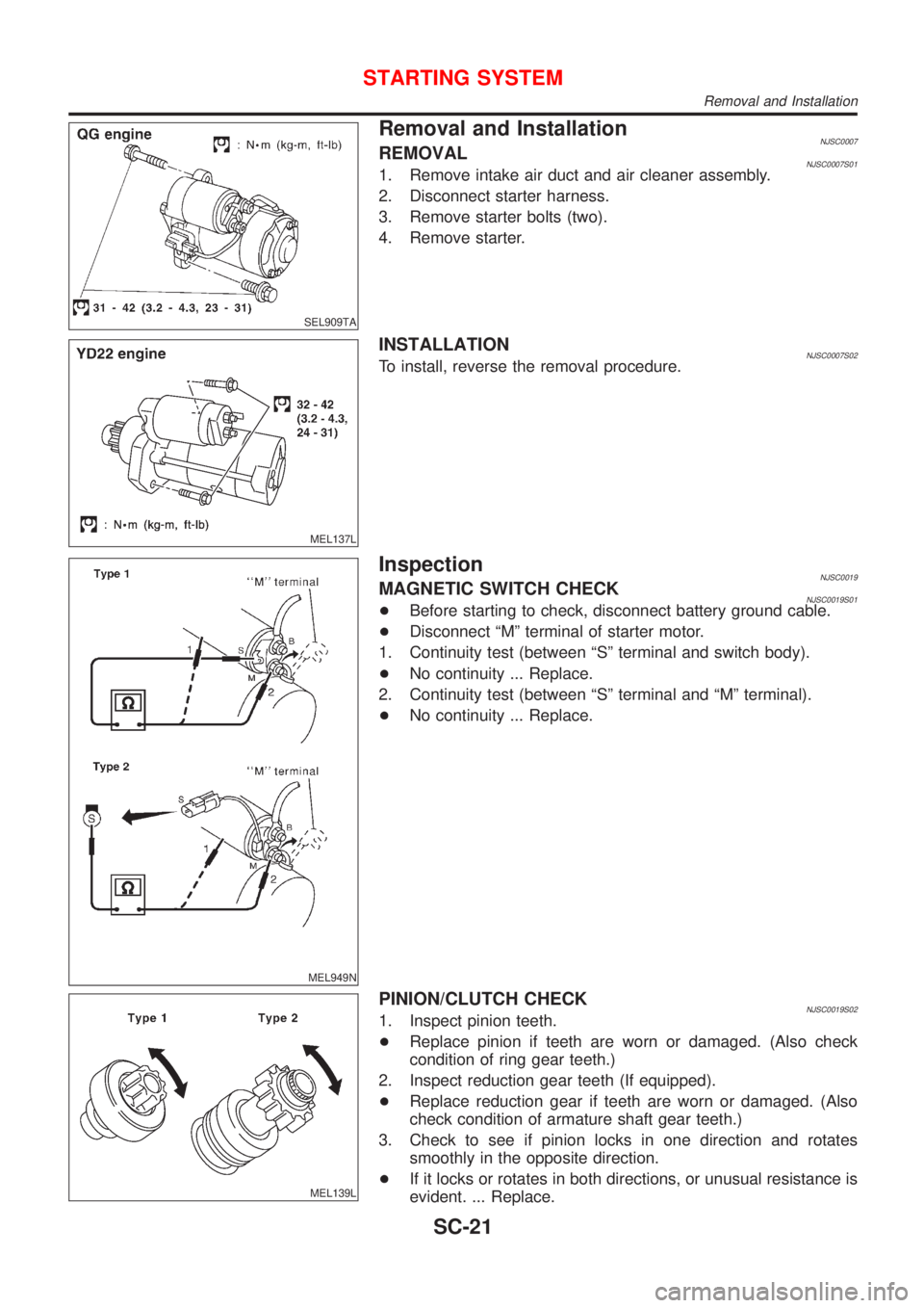
Removal and InstallationNJSC0007REMOVALNJSC0007S011. Remove intake air duct and air cleaner assembly.
2. Disconnect starter harness.
3. Remove starter bolts (two).
4. Remove starter.
MEL137L
INSTALLATIONNJSC0007S02To install, reverse the removal procedure.
MEL949N
InspectionNJSC0019MAGNETIC SWITCH CHECKNJSC0019S01+Before starting to check, disconnect battery ground cable.
+Disconnect ªMº terminal of starter motor.
1. Continuity test (between ªSº terminal and switch body).
+No continuity ... Replace.
2. Continuity test (between ªSº terminal and ªMº terminal).
+No continuity ... Replace.
MEL139L
PINION/CLUTCH CHECKNJSC0019S021. Inspect pinion teeth.
+Replace pinion if teeth are worn or damaged. (Also check
condition of ring gear teeth.)
2. Inspect reduction gear teeth (If equipped).
+Replace reduction gear if teeth are worn or damaged. (Also
check condition of armature shaft gear teeth.)
3. Check to see if pinion locks in one direction and rotates
smoothly in the opposite direction.
+If it locks or rotates in both directions, or unusual resistance is
evident. ... Replace.
STARTING SYSTEM
Removal and Installation
SC-21
Page 2822 of 2898
System DescriptionNJSC0009SEDANNJSC0009S01The alternator provides DC voltage to operate the vehicle's electrical system and to keep the battery charged.
The voltage output is controlled by the IC regulator.
Power is supplied at all times to alternator terminal 4 (S) through:
+10A fuse (No. 33, located in the fuse and fusible link box).
Terminal B supplies power to charge the battery and operate the vehicle's electrical system. Output voltage
is controlled by the IC regulator at terminal 4 (S) detecting the input voltage. The charging circuit is protected
by the 80A (A/T models with QG13DE engine and M/T models with gasoline engine) or 100A (A/T models
except QG13DE engine and diesel engine models) fusible link.
The alternator is grounded to the engine block.
With the ignition switch in the ON or START position, power is supplied
+through 10A fuse [No. 30, located in the fuse block (J/B)]
+to combination meter terminal 17 (Models with tachometer) or 22 (Models without tachometer) for the
charge warning lamp.
Ground is supplied to terminal 62 (Models with tachometer) or 61 (Models without tachometer) of the combi-
nation meter through terminal 3 (L) of the alternator. With power and ground supplied, the charge warning lamp
will illuminate. When the alternator is providing sufficient voltage with the engine running, the ground is opened
and the charge warning lamp will go off.
If the charge warning lamp illuminates with the engine running, a fault is indicated.
HATCHBACKNJSC0009S02The alternator provides DC voltage to operate the vehicle's electrical system and to keep the battery charged.
The voltage output is controlled by the IC regulator.
Power is supplied at all times to alternator terminal 4 (S) through:
+10A fuse (No. 33, located in the fuse and fusible link box).
Terminal B supplies power to charge the battery and operate the vehicle's electrical system. Output voltage
is controlled by the IC regulator at terminal 4 (S) detecting the input voltage. The charging circuit is protected
by the 80A (Gasoline engine models without daytime light system) or 100A (A/T models, diesel engine mod-
els and gasoline engine models with daytime light system) fusible link.
The alternator is grounded to the engine block.
With the ignition switch in the ON or START position, power is supplied
+through 10A fuse [No. 30, located in the fuse block (J/B)]
+to combination meter terminal 40 or 1
Ground is supplied to terminal 1 or 28 of the combination meter through terminal 3 (L) of the alternator. With
power and ground supplied, the charge warning lamp will illuminate. When the alternator is providing suffi-
cient voltage with the engine running, the ground is opened and the charge warning lamp will go off.
If the charge warning lamp illuminates with the engine running, a fault is indicated.
CHARGING SYSTEM
System Description
SC-26
Page 2831 of 2898

INSTALLATIONNJSC0013S02To install, reverse the removal procedure.
SEL032Z
DisassemblyNJSC0021REAR COVERNJSC0021S01CAUTION:
Rear cover may be hard to remove because a ring is used to
lock outer race of rear bearing. To facilitate removal of rear
cover, heat just bearing box section with a 200W soldering
iron.
Do not use a heat gun, as it can damage diode assembly.
REAR BEARINGNJSC0021S02CAUTION:
+Do not reuse rear bearing after removal. Replace with a
new one.
+Do not lubricate rear bearing outer race.
SEL033Z
InspectionNJSC0022ROTOR CHECKNJSC0022S011. Resistance test
Resistance: Refer to SDS (SC-39).
+Not within the specified values ... Replace rotor.
2. Insulator test
+Continuity exists ... Replace rotor.
3. Check slip ring for wear.
Slip ring minimum outer diameter:
Refer to SDS (SC-39).
+Not within the specified values ... Replace rotor.
CHARGING SYSTEM
Removal and Installation (Cont'd)
SC-35
Page 2841 of 2898
NJST0006
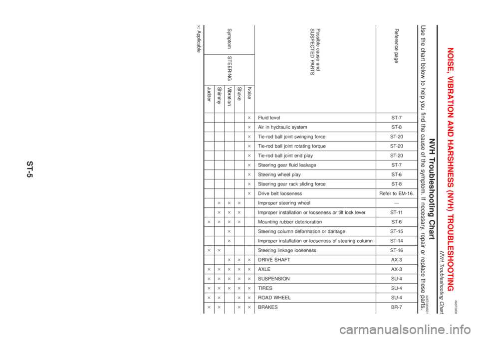
NVH Troubleshooting ChartNJST0006S01Use the chart below to help you find the cause of the symptom. If necessary, repair or replace these parts.
Reference pageST-7
ST-8
ST-20
ST-20
ST-20
ST-7
ST-6
ST-8
Refer to EM-16.
Ð
ST-11
ST-6
ST-15
ST-14
ST-16
AX-3
AX-3
SU-4
SU-4
SU-4
BR-7
Possible cause and
SUSPECTED PARTS
Fluid level
Air in hydraulic system
Tie-rod ball joint swinging force
Tie-rod ball joint rotating torque
Tie-rod ball joint end play
Steering gear fluid leakage
Steering wheel play
Steering gear rack sliding force
Drive belt looseness
Improper steering wheel
Improper installation or looseness or tilt lock lever
Mounting rubber deterioration
Steering column deformation or damage
Improper installation or looseness of steering column
Steering linkage looseness
DRIVE SHAFT
AXLE
SUSPENSION
TIRES
ROAD WHEEL
BRAKES
Symptom STEERINGNoise´´´´´´´´´ ´´´´´´
Shake´´´ ´´´´´´
Vibration´´´´´ ´´´´
Shimmy´´´ ´ ´´´´´
Judder´ ´ ´´´´´
´: Applicable
NOISE, VIBRATION AND HARSHNESS (NVH) TROUBLESHOOTING
NVH Troubleshooting Chart
ST-5
Page 2842 of 2898
SST489B
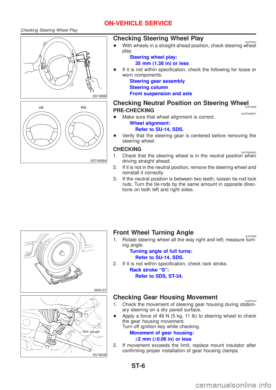
Checking Steering Wheel PlayNJST0007+With wheels in a straight-ahead position, check steering wheel
play.
Steering wheel play:
35 mm (1.38 in) or less
+If it is not within specification, check the following for loose or
worn components.
Steering gear assembly
Steering column
Front suspension and axle
SST490BA
Checking Neutral Position on Steering WheelNJST0008PRE-CHECKINGNJST0008S01+Make sure that wheel alignment is correct.
Wheel alignment:
Refer to SU-14, SDS.
+Verify that the steering gear is centered before removing the
steering wheel.
CHECKINGNJST0008S021. Check that the steering wheel is in the neutral position when
driving straight ahead.
2. If it is not in the neutral position, remove the steering wheel and
reinstall it correctly.
3. If the neutral position is between two teeth, loosen tie-rod lock
nuts. Turn the tie-rods by the same amount in opposite direc-
tions on both left and right sides.
SMA127
Front Wheel Turning AngleNJST00091. Rotate steering wheel all the way right and left; measure turn-
ing angle.
Turning angle of full turns:
Refer to SU-14, SDS.
2. If it is not within specification, check rack stroke.
Rack stroke ªSº:
Refer to SDS, ST-34.
SST663B
Checking Gear Housing MovementNJST00101. Check the movement of steering gear housing during station-
ary steering on a dry paved surface.
+Apply a force of 49 N (5 kg, 11 lb) to steering wheel to check
the gear housing movement.
Turn off ignition key while checking.
Movement of gear housing:
±2mm(±0.08 in) or less
2. If movement exceeds the limit, replace mount insulator after
confirming proper installation of gear housing clamps.
ON-VEHICLE SERVICE
Checking Steering Wheel Play
ST-6
Page 2843 of 2898
Checking and Adjusting Drive BeltsNJST0011Refer to EM-16, ªChecking Drive Beltsº.
SMA851B
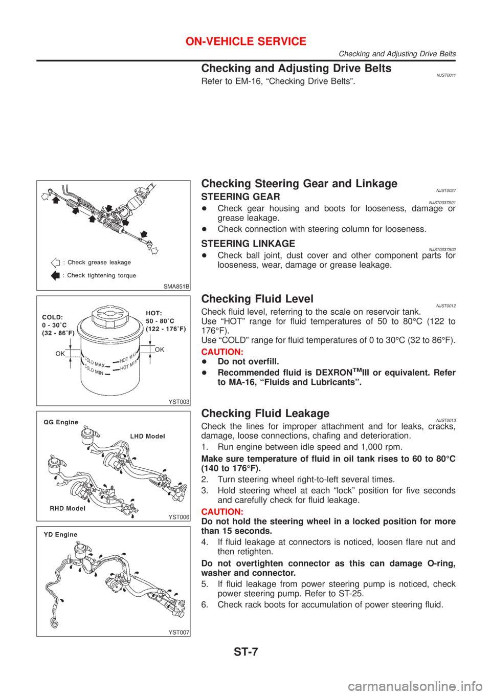
Checking Steering Gear and LinkageNJST0037STEERING GEARNJST0037S01+Check gear housing and boots for looseness, damage or
grease leakage.
+Check connection with steering column for looseness.
STEERING LINKAGENJST0037S02+Check ball joint, dust cover and other component parts for
looseness, wear, damage or grease leakage.
YST003
Checking Fluid LevelNJST0012Check fluid level, referring to the scale on reservoir tank.
Use ªHOTº range for fluid temperatures of 50 to 80ÉC (122 to
176ÉF).
Use ªCOLDº range for fluid temperatures of 0 to 30ÉC (32 to 86ÉF).
CAUTION:
+Do not overfill.
+Recommended fluid is DEXRON
TMIII or equivalent. Refer
to MA-16, ªFluids and Lubricantsº.
YST006
YST007
Checking Fluid LeakageNJST0013Check the lines for improper attachment and for leaks, cracks,
damage, loose connections, chafing and deterioration.
1. Run engine between idle speed and 1,000 rpm.
Make sure temperature of fluid in oil tank rises to 60 to 80ÉC
(140 to 176ÉF).
2. Turn steering wheel right-to-left several times.
3. Hold steering wheel at each ªlockº position for five seconds
and carefully check for fluid leakage.
CAUTION:
Do not hold the steering wheel in a locked position for more
than 15 seconds.
4. If fluid leakage at connectors is noticed, loosen flare nut and
then retighten.
Do not overtighten connector as this can damage O-ring,
washer and connector.
5. If fluid leakage from power steering pump is noticed, check
power steering pump. Refer to ST-25.
6. Check rack boots for accumulation of power steering fluid.
ON-VEHICLE SERVICE
Checking and Adjusting Drive Belts
ST-7
Page 2845 of 2898
Rack sliding force (Sedan only):
Not more than 294 N (30 kg, 66 lb)
Maximum force deviation:
147 N (15 kg, 33 lb)
6. If rack sliding force is not within specification, overhaul steer-
ing gear assembly.
7. If rack sliding force is OK, inspect steering column. Refer to
ST-14.
SST834-I
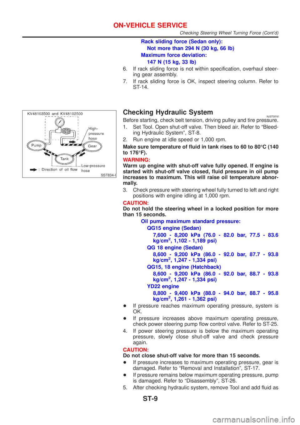
Checking Hydraulic SystemNJST0016Before starting, check belt tension, driving pulley and tire pressure.
1. Set Tool. Open shut-off valve. Then bleed air. Refer to ªBleed-
ing Hydraulic Systemº, ST-8.
2. Run engine at idle speed or 1,000 rpm.
Make sure temperature of fluid in tank rises to 60 to 80ÉC (140
to 176ÉF).
WARNING:
Warm up engine with shut-off valve fully opened. If engine is
started with shut-off valve closed, fluid pressure in oil pump
increases to maximum. This will raise oil temperature abnor-
mally.
3. Check pressure with steering wheel fully turned to left and right
positions with engine idling at 1,000 rpm.
CAUTION:
Do not hold the steering wheel in a locked position for more
than 15 seconds.
Oil pump maximum standard pressure:
QG15 engine (Sedan)
7,600 - 8,200 kPa (76.0 - 82.0 bar, 77.5 - 83.6
kg/cm
2, 1,102 - 1,189 psi)
QG 18 engine (Sedan)
8,600 - 9,200 kPa (86.0 - 92.0 bar, 87.7 - 93.8
kg/cm
2, 1,247 - 1,334 psi)
QG15, 18 engine (Hatchback)
8,600 - 9,200 kPa (86.0 - 92.0 bar, 88.7 - 93.8
kg/cm
2, 1,247 - 1,334 psi)
YD22 engine
8,800 - 9,400 kPa (88.0 - 94.0 bar, 88.7 - 95.8
kg/cm
2, 1,261 - 1,362 psi)
+If pressure reaches maximum operating pressure, system is
OK.
+If pressure increases above maximum operating pressure,
check power steering pump flow control valve. Refer to ST-25.
4. If power steering pressure is below the maximum operating
pressure, slowly close shut-off valve and check pressure
again.
CAUTION:
Do not close shut-off valve for more than 15 seconds.
+If pressure increases to maximum operating pressure, gear is
damaged. Refer to ªRemoval and Installationº, ST-17.
+If pressure remains below maximum operating pressure, pump
is damaged. Refer to ªDisassemblyº, ST-26.
5. After checking hydraulic system, remove Tool and add fluid as
ON-VEHICLE SERVICE
Checking Steering Wheel Turning Force (Cont'd)
ST-9