ENGINE MECHANICAL NISSAN ALMERA 2001 Service Manual
[x] Cancel search | Manufacturer: NISSAN, Model Year: 2001, Model line: ALMERA, Model: NISSAN ALMERA 2001Pages: 2898, PDF Size: 60.76 MB
Page 56 of 2898

SAT964I
Malfunction Indicator (MI)=NJAT02551. The malfunction indicator will light up when the ignition switch
is turned ON without the engine running. This is for checking
the lamp.
+If the malfunction indicator does not light up, refer to EL-185,
ªWarning Lampsº.
(Or see MI & CONSULT-II in EC section. Refer to EC-74,
ªDescriptionº, ªMalfunction Indicator (MI)º and EC-83, ªCON-
SULT-IIº.)
2. When the engine is started, the malfunction indicator should go
off.
If the lamp remains on, the on board diagnostic system has
detected an emission-related (EURO-OBD) malfunction. For
detail, refer to EC-59, ªON BOARD DIAGNOSTIC SYSTEM
DESCRIPTIONº.
CONSULT-IINJAT0256After performing ªSELF-DIAGNOSTIC PROCEDURE (WITH CON-
SULT-II)º (AT-55), place check marks for results on the ªDIAGNOS-
TIC WORKSHEETº, AT-76. Reference pages are provided follow-
ing the items.
NOTICE:
1) The CONSULT-II electrically displays shift timing and lock-up
timing (that is, operation timing of each solenoid).
Check for time difference between actual shift timing and the
CONSULT-II display. If the difference is noticeable, mechani-
cal parts (except solenoids, sensors, etc.) may be malfunction-
ing. Check mechanical parts using applicable diagnostic pro-
cedures.
2) Shift schedule (which implies gear position) displayed on
CONSULT-II and that indicated in Service Manual may differ
slightly. This occurs because of the following reasons:
+Actual shift schedule has more or less tolerance or allowance,
+Shift schedule indicated in Service Manual refers to the point
where shifts start, and
+Gear position displayed on CONSULT-II indicates the point
where shifts are completed.
3) Shift solenoid valve ªAº or ªBº is displayed on CONSULT-II at
the start of shifting. Gear position is displayed upon completion
of shifting (which is computed by TCM).
4) Additional CONSULT-II information can be found in the Opera-
tion Manual supplied with the CONSULT-II unit.
ON BOARD DIAGNOSTIC SYSTEM
DESCRIPTION
EURO-OBD
Malfunction Indicator (MI)
AT-54
Page 206 of 2898
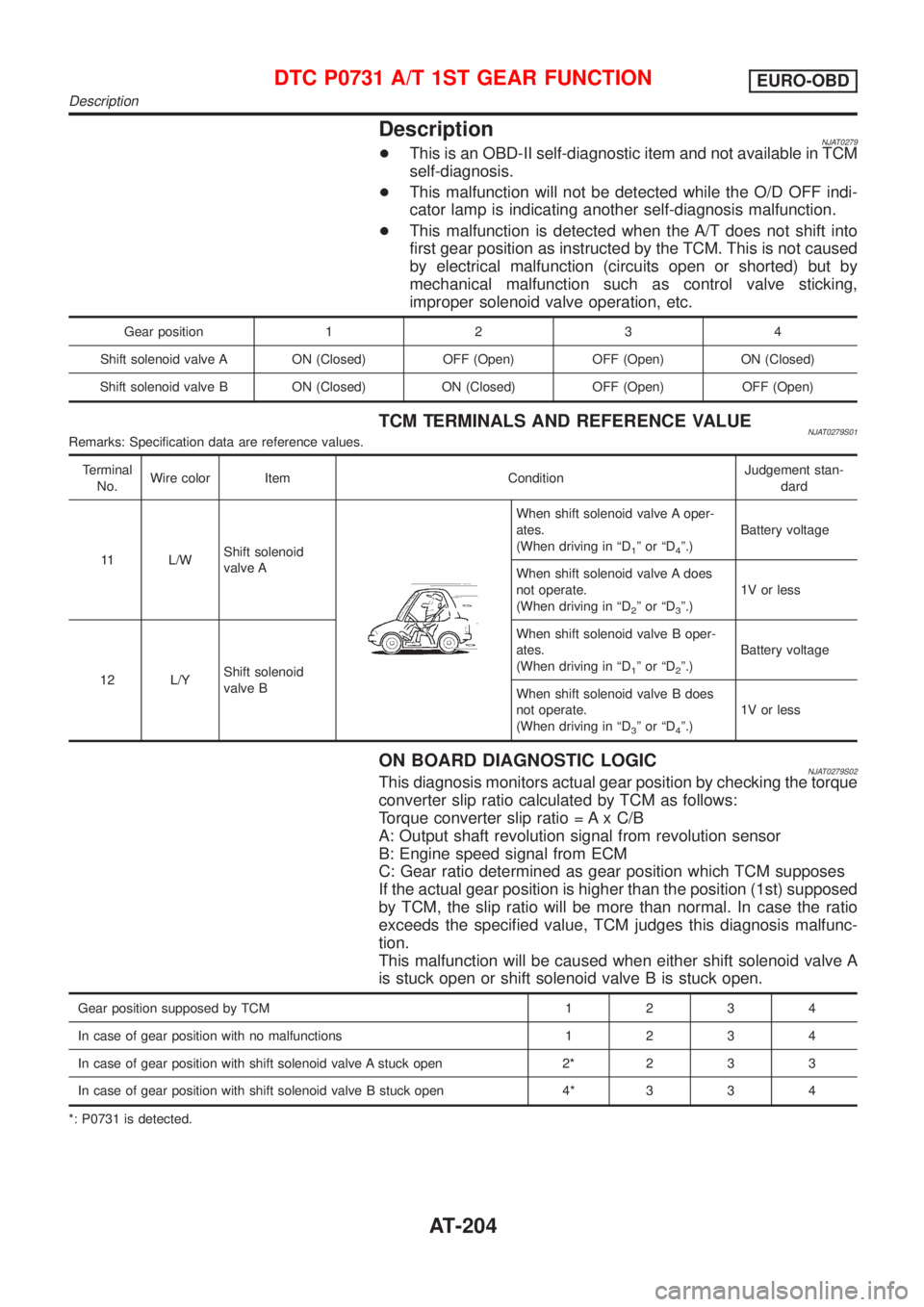
DescriptionNJAT0279+This is an OBD-II self-diagnostic item and not available in TCM
self-diagnosis.
+This malfunction will not be detected while the O/D OFF indi-
cator lamp is indicating another self-diagnosis malfunction.
+This malfunction is detected when the A/T does not shift into
first gear position as instructed by the TCM. This is not caused
by electrical malfunction (circuits open or shorted) but by
mechanical malfunction such as control valve sticking,
improper solenoid valve operation, etc.
Gear position1234
Shift solenoid valve A ON (Closed) OFF (Open) OFF (Open) ON (Closed)
Shift solenoid valve B ON (Closed) ON (Closed) OFF (Open) OFF (Open)
TCM TERMINALS AND REFERENCE VALUENJAT0279S01Remarks: Specification data are reference values.
Terminal
No.Wire color Item ConditionJudgement stan-
dard
11 L/WShift solenoid
valve A
When shift solenoid valve A oper-
ates.
(When driving in ªD
1ºorªD4º.)Battery voltage
When shift solenoid valve A does
not operate.
(When driving in ªD
2ºorªD3º.)1V or less
12 L/YShift solenoid
valve BWhen shift solenoid valve B oper-
ates.
(When driving in ªD
1ºorªD2º.)Battery voltage
When shift solenoid valve B does
not operate.
(When driving in ªD
3ºorªD4º.)1V or less
ON BOARD DIAGNOSTIC LOGICNJAT0279S02This diagnosis monitors actual gear position by checking the torque
converter slip ratio calculated by TCM as follows:
Torque converter slip ratio = A x C/B
A: Output shaft revolution signal from revolution sensor
B: Engine speed signal from ECM
C: Gear ratio determined as gear position which TCM supposes
If the actual gear position is higher than the position (1st) supposed
by TCM, the slip ratio will be more than normal. In case the ratio
exceeds the specified value, TCM judges this diagnosis malfunc-
tion.
This malfunction will be caused when either shift solenoid valve A
is stuck open or shift solenoid valve B is stuck open.
Gear position supposed by TCM1234
In case of gear position with no malfunctions1234
In case of gear position with shift solenoid valve A stuck open 2* 2 3 3
In case of gear position with shift solenoid valve B stuck open 4* 3 3 4
*: P0731 is detected.
DTC P0731 A/T 1ST GEAR FUNCTIONEURO-OBD
Description
AT-204
Page 213 of 2898
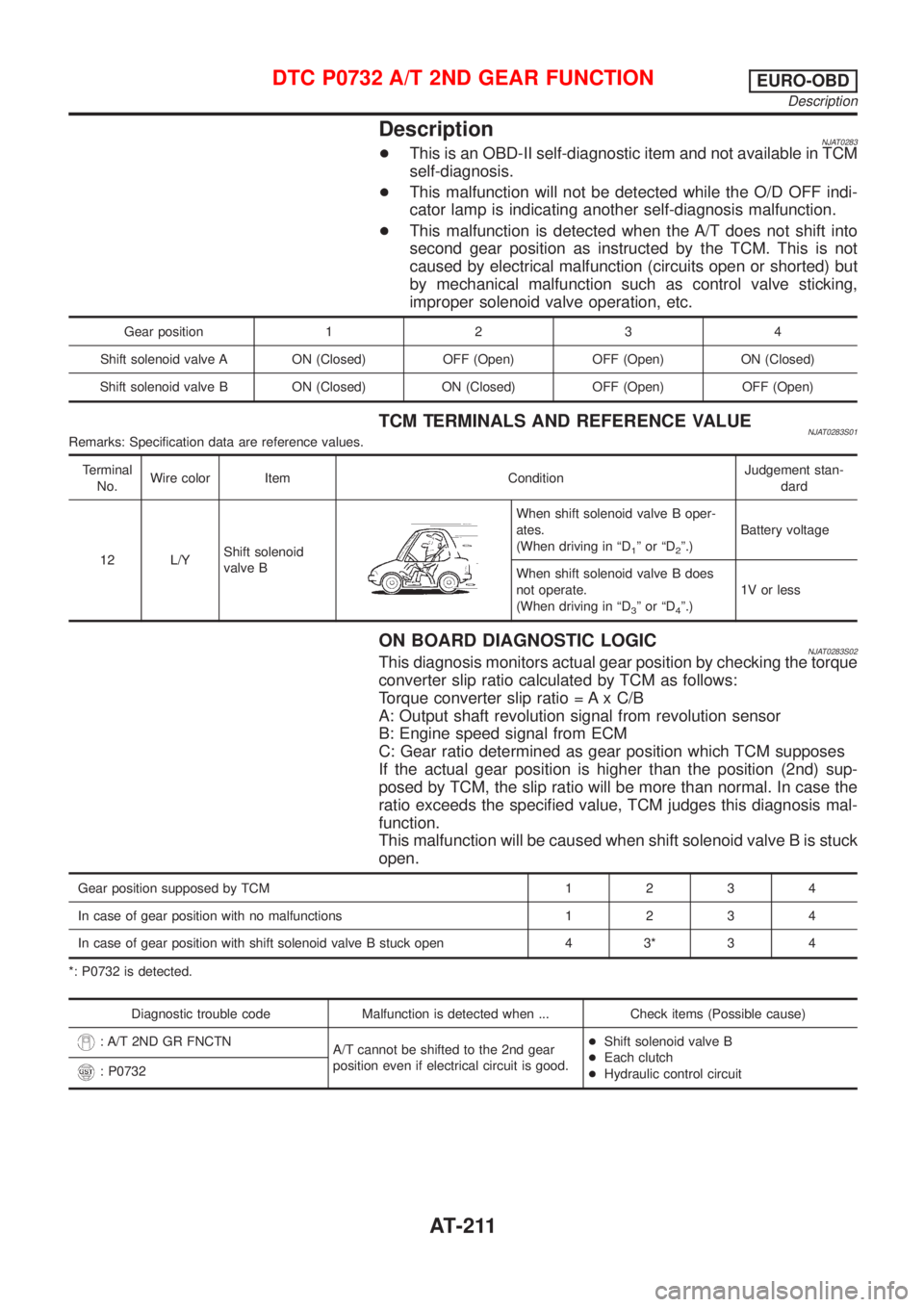
DescriptionNJAT0283+This is an OBD-II self-diagnostic item and not available in TCM
self-diagnosis.
+This malfunction will not be detected while the O/D OFF indi-
cator lamp is indicating another self-diagnosis malfunction.
+This malfunction is detected when the A/T does not shift into
second gear position as instructed by the TCM. This is not
caused by electrical malfunction (circuits open or shorted) but
by mechanical malfunction such as control valve sticking,
improper solenoid valve operation, etc.
Gear position1234
Shift solenoid valve A ON (Closed) OFF (Open) OFF (Open) ON (Closed)
Shift solenoid valve B ON (Closed) ON (Closed) OFF (Open) OFF (Open)
TCM TERMINALS AND REFERENCE VALUENJAT0283S01Remarks: Specification data are reference values.
Terminal
No.Wire color Item ConditionJudgement stan-
dard
12 L/YShift solenoid
valve B
When shift solenoid valve B oper-
ates.
(When driving in ªD
1ºorªD2º.)Battery voltage
When shift solenoid valve B does
not operate.
(When driving in ªD
3ºorªD4º.)1V or less
ON BOARD DIAGNOSTIC LOGICNJAT0283S02This diagnosis monitors actual gear position by checking the torque
converter slip ratio calculated by TCM as follows:
Torque converter slip ratio = A x C/B
A: Output shaft revolution signal from revolution sensor
B: Engine speed signal from ECM
C: Gear ratio determined as gear position which TCM supposes
If the actual gear position is higher than the position (2nd) sup-
posed by TCM, the slip ratio will be more than normal. In case the
ratio exceeds the specified value, TCM judges this diagnosis mal-
function.
This malfunction will be caused when shift solenoid valve B is stuck
open.
Gear position supposed by TCM1234
In case of gear position with no malfunctions1234
In case of gear position with shift solenoid valve B stuck open 4 3* 3 4
*: P0732 is detected.
Diagnostic trouble code Malfunction is detected when ... Check items (Possible cause)
: A/T 2ND GR FNCTN
A/T cannot be shifted to the 2nd gear
position even if electrical circuit is good.+Shift solenoid valve B
+Each clutch
+Hydraulic control circuit
: P0732
DTC P0732 A/T 2ND GEAR FUNCTIONEURO-OBD
Description
AT-211
Page 219 of 2898
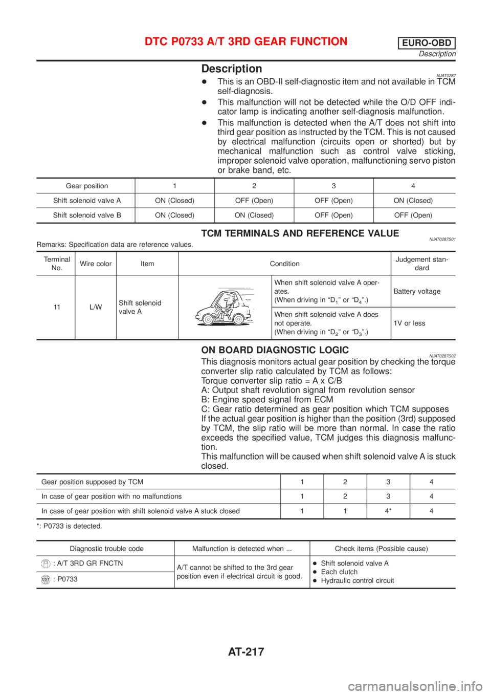
DescriptionNJAT0287+This is an OBD-II self-diagnostic item and not available in TCM
self-diagnosis.
+This malfunction will not be detected while the O/D OFF indi-
cator lamp is indicating another self-diagnosis malfunction.
+This malfunction is detected when the A/T does not shift into
third gear position as instructed by the TCM. This is not caused
by electrical malfunction (circuits open or shorted) but by
mechanical malfunction such as control valve sticking,
improper solenoid valve operation, malfunctioning servo piston
or brake band, etc.
Gear position1234
Shift solenoid valve A ON (Closed) OFF (Open) OFF (Open) ON (Closed)
Shift solenoid valve B ON (Closed) ON (Closed) OFF (Open) OFF (Open)
TCM TERMINALS AND REFERENCE VALUENJAT0287S01Remarks: Specification data are reference values.
Terminal
No.Wire color Item ConditionJudgement stan-
dard
11 L/WShift solenoid
valve A
When shift solenoid valve A oper-
ates.
(When driving in ªD
1ºorªD4º.)Battery voltage
When shift solenoid valve A does
not operate.
(When driving in ªD
2ºorªD3º.)1V or less
ON BOARD DIAGNOSTIC LOGICNJAT0287S02This diagnosis monitors actual gear position by checking the torque
converter slip ratio calculated by TCM as follows:
Torque converter slip ratio = A x C/B
A: Output shaft revolution signal from revolution sensor
B: Engine speed signal from ECM
C: Gear ratio determined as gear position which TCM supposes
If the actual gear position is higher than the position (3rd) supposed
by TCM, the slip ratio will be more than normal. In case the ratio
exceeds the specified value, TCM judges this diagnosis malfunc-
tion.
This malfunction will be caused when shift solenoid valve A is stuck
closed.
Gear position supposed by TCM1234
In case of gear position with no malfunctions1234
In case of gear position with shift solenoid valve A stuck closed 1 1 4* 4
*: P0733 is detected.
Diagnostic trouble code Malfunction is detected when ... Check items (Possible cause)
: A/T 3RD GR FNCTN
A/T cannot be shifted to the 3rd gear
position even if electrical circuit is good.+Shift solenoid valve A
+Each clutch
+Hydraulic control circuit
: P0733
DTC P0733 A/T 3RD GEAR FUNCTIONEURO-OBD
Description
AT-217
Page 225 of 2898
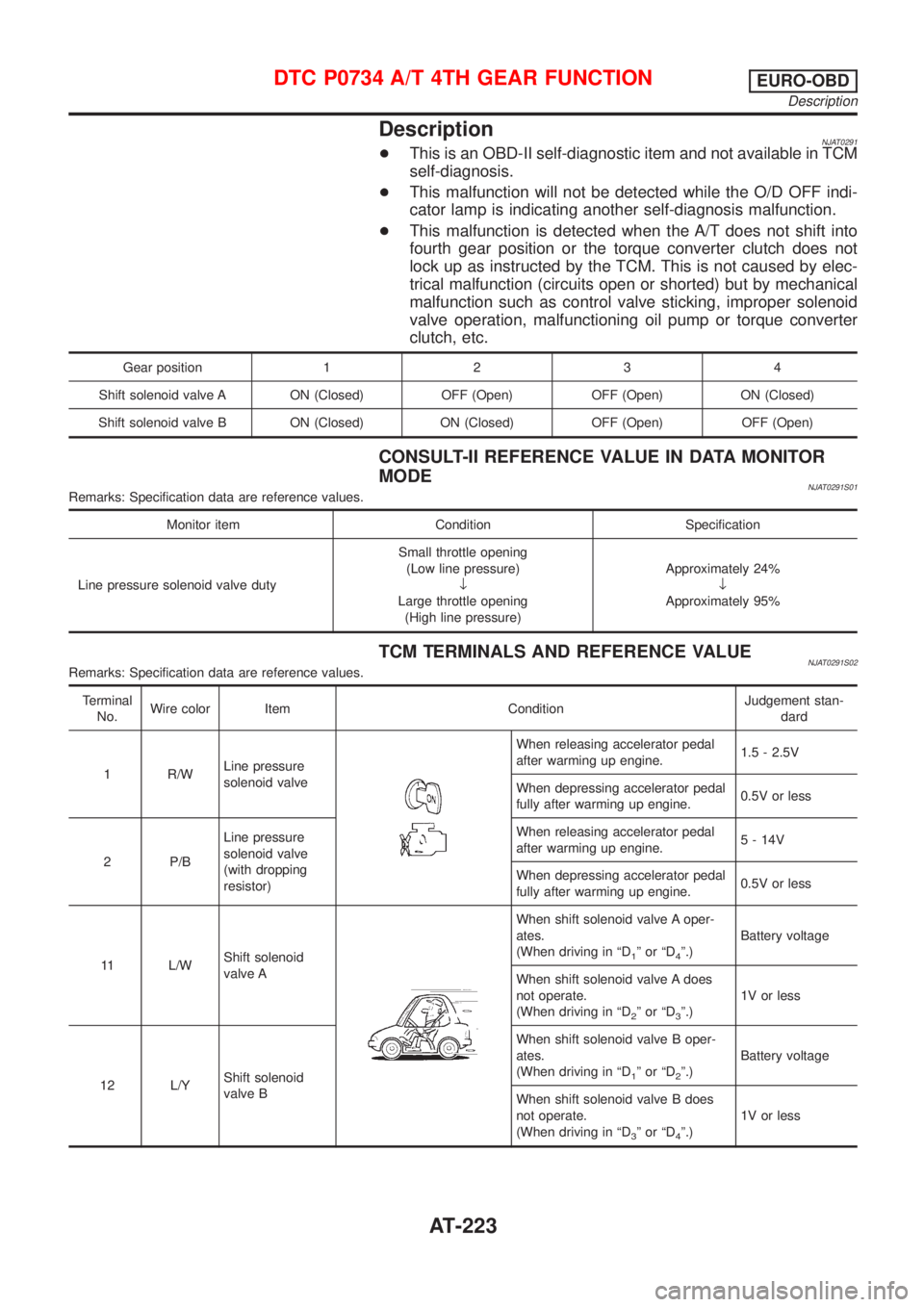
DescriptionNJAT0291+This is an OBD-II self-diagnostic item and not available in TCM
self-diagnosis.
+This malfunction will not be detected while the O/D OFF indi-
cator lamp is indicating another self-diagnosis malfunction.
+This malfunction is detected when the A/T does not shift into
fourth gear position or the torque converter clutch does not
lock up as instructed by the TCM. This is not caused by elec-
trical malfunction (circuits open or shorted) but by mechanical
malfunction such as control valve sticking, improper solenoid
valve operation, malfunctioning oil pump or torque converter
clutch, etc.
Gear position1234
Shift solenoid valve A ON (Closed) OFF (Open) OFF (Open) ON (Closed)
Shift solenoid valve B ON (Closed) ON (Closed) OFF (Open) OFF (Open)
CONSULT-II REFERENCE VALUE IN DATA MONITOR
MODE
NJAT0291S01Remarks: Specification data are reference values.
Monitor item Condition Specification
Line pressure solenoid valve dutySmall throttle opening
(Low line pressure)
¯
Large throttle opening
(High line pressure)Approximately 24%
¯
Approximately 95%
TCM TERMINALS AND REFERENCE VALUENJAT0291S02Remarks: Specification data are reference values.
Terminal
No.Wire color Item ConditionJudgement stan-
dard
1 R/WLine pressure
solenoid valve
When releasing accelerator pedal
after warming up engine.1.5 - 2.5V
When depressing accelerator pedal
fully after warming up engine.0.5V or less
2 P/BLine pressure
solenoid valve
(with dropping
resistor)When releasing accelerator pedal
after warming up engine.5 - 14V
When depressing accelerator pedal
fully after warming up engine.0.5V or less
11 L/WShift solenoid
valve A
When shift solenoid valve A oper-
ates.
(When driving in ªD
1ºorªD4º.)Battery voltage
When shift solenoid valve A does
not operate.
(When driving in ªD
2ºorªD3º.)1V or less
12 L/YShift solenoid
valve BWhen shift solenoid valve B oper-
ates.
(When driving in ªD
1ºorªD2º.)Battery voltage
When shift solenoid valve B does
not operate.
(When driving in ªD
3ºorªD4º.)1V or less
DTC P0734 A/T 4TH GEAR FUNCTIONEURO-OBD
Description
AT-223
Page 812 of 2898
![NISSAN ALMERA 2001 Service Manual Monitored item [Unit]ECM
input
signalsMain
signalsDescription Remarks
HO2S2 MNTR (B1)
[RICH/LEAN]j+Display of heated oxygen sensor 2 (rear)
signal:
RICH ... means the amount of oxygen after
three way](/img/5/57348/w960_57348-811.png "NISSAN ALMERA 2001 Service Manual Monitored item [Unit]ECM
input
signalsMain
signalsDescription Remarks
HO2S2 MNTR (B1)
[RICH/LEAN]j+Display of heated oxygen sensor 2 (rear)
signal:
RICH ... means the amount of oxygen after
three way")
Monitored item [Unit]ECM
input
signalsMain
signalsDescription Remarks
HO2S2 MNTR (B1)
[RICH/LEAN]j+Display of heated oxygen sensor 2 (rear)
signal:
RICH ... means the amount of oxygen after
three way catalyst is relatively small.
LEAN ... means the amount of oxygen after
three way catalyst is relatively large.+When the engine is stopped, a cer-
tain value is indicated.
VHCL SPEED SE
[km/h] or [mph]jj+The vehicle speed computed from the
vehicle speed sensor signal is displayed.
BATTERY VOLT [V]j+The power supply voltage of ECM is dis-
played.
THRTL POS SEN [V]jj+The throttle position sensor signal voltage is
displayed.
FUEL T/TMP SE
[ÉC] or [ÉF]*+The fuel temperature judged from the fuel
tank temperature sensor signal voltage is
displayed.
INT/A TEMP SE
[ÉC] or [ÉF]j+The intake air temperature determined by
the signal voltage of the intake air tempera-
ture sensor is indicated.
EGR TEMP SEN [V]*jj+The signal voltage of the EGR temperature
sensor is displayed.
START SIGNAL
[ON/OFF]jj+Indicates [ON/OFF] condition from the
starter signal.+After starting the engine, [OFF] is
displayed regardless of the starter
signal.
CLSD THL POS
[ON/OFF]jj+Indicates idle position [ON/OFF] computed
by ECM according to the throttle position
sensor signal.
CLSD THL/P SW
[ON/OFF]*j+Indicates mechanical contact [ON/OFF]
condition of the closed throttle position
switch.
AIR COND SIG
[ON/OFF]jj+Indicates [ON/OFF] condition of the air con-
ditioner switch as determined by the air
conditioning signal.
P/N POSI SW
[ON/OFF]jj+Indicates [ON/OFF] condition from the PNP
switch signal.
PW/ST SIGNAL
[ON/OFF]jj+Indicates [ON/OFF] condition of the power
steering oil pressure switch determined by
the power steering oil pressure switch sig-
nal.
LOAD SIGNAL
[ON/OFF]jj+Indicates [ON/OFF] condition from the elec-
trical load signal and/or lighting switch.
ON ... rear defogger is operating and/or
lighting switch is on.
OFF ... rear defogger is not operating and
lighting switch is not on.
IGNITION SW
[ON/OFF]j+Indicates [ON/OFF] condition from ignition
switch.
HEATER FAN SW
[ON/OFF]j+Indicates [ON/OFF] condition from the
heater fan switch.
INJ PULSE-B1
[msec]j+Indicates the actual fuel injection pulse
width compensated by ECM according to
the input signals.+When the engine is stopped, a cer-
tain computed value is indicated.
ON BOARD DIAGNOSTIC SYSTEM DESCRIPTIONQG
CONSULT-II (Cont'd)
EC-88
Page 823 of 2898
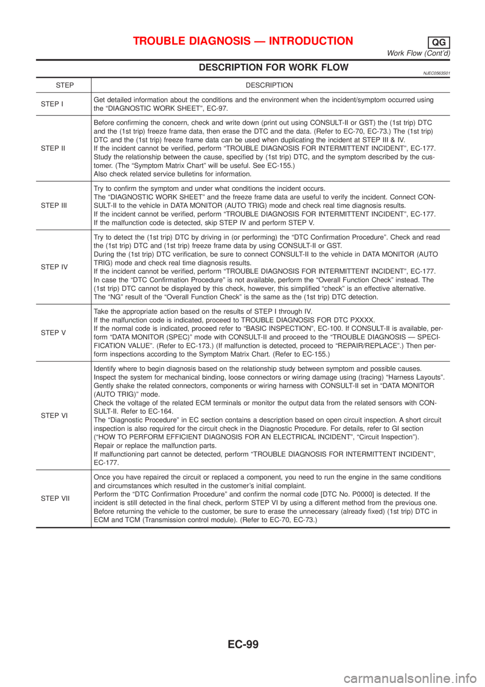
DESCRIPTION FOR WORK FLOWNJEC0563S01
STEP DESCRIPTION
STEP IGet detailed information about the conditions and the environment when the incident/symptom occurred using
the ªDIAGNOSTIC WORK SHEETº, EC-97.
STEP IIBefore confirming the concern, check and write down (print out using CONSULT-II or GST) the (1st trip) DTC
and the (1st trip) freeze frame data, then erase the DTC and the data. (Refer to EC-70, EC-73.) The (1st trip)
DTC and the (1st trip) freeze frame data can be used when duplicating the incident at STEP III & IV.
If the incident cannot be verified, perform ªTROUBLE DIAGNOSIS FOR INTERMITTENT INCIDENTº, EC-177.
Study the relationship between the cause, specified by (1st trip) DTC, and the symptom described by the cus-
tomer. (The ªSymptom Matrix Chartº will be useful. See EC-155.)
Also check related service bulletins for information.
STEP IIITry to confirm the symptom and under what conditions the incident occurs.
The ªDIAGNOSTIC WORK SHEETº and the freeze frame data are useful to verify the incident. Connect CON-
SULT-II to the vehicle in DATA MONITOR (AUTO TRIG) mode and check real time diagnosis results.
If the incident cannot be verified, perform ªTROUBLE DIAGNOSIS FOR INTERMITTENT INCIDENTº, EC-177.
If the malfunction code is detected, skip STEP IV and perform STEP V.
STEP IVTry to detect the (1st trip) DTC by driving in (or performing) the ªDTC Confirmation Procedureº. Check and read
the (1st trip) DTC and (1st trip) freeze frame data by using CONSULT-II or GST.
During the (1st trip) DTC verification, be sure to connect CONSULT-II to the vehicle in DATA MONITOR (AUTO
TRIG) mode and check real time diagnosis results.
If the incident cannot be verified, perform ªTROUBLE DIAGNOSIS FOR INTERMITTENT INCIDENTº, EC-177.
In case the ªDTC Confirmation Procedureº is not available, perform the ªOverall Function Checkº instead. The
(1st trip) DTC cannot be displayed by this check, however, this simplified ªcheckº is an effective alternative.
The ªNGº result of the ªOverall Function Checkº is the same as the (1st trip) DTC detection.
STEP VTake the appropriate action based on the results of STEP I through IV.
If the malfunction code is indicated, proceed to TROUBLE DIAGNOSIS FOR DTC PXXXX.
If the normal code is indicated, proceed refer to ªBASIC INSPECTIONº, EC-100. If CONSULT-II is available, per-
form ªDATA MONITOR (SPEC)º mode with CONSULT-II and proceed to the ªTROUBLE DIAGNOSIS Ð SPECI-
FICATION VALUEº. (Refer to EC-173.) (If malfunction is detected, proceed to ªREPAIR/REPLACEº.) Then per-
form inspections according to the Symptom Matrix Chart. (Refer to EC-155.)
STEP VIIdentify where to begin diagnosis based on the relationship study between symptom and possible causes.
Inspect the system for mechanical binding, loose connectors or wiring damage using (tracing) ªHarness Layoutsº.
Gently shake the related connectors, components or wiring harness with CONSULT-II set in ªDATA MONITOR
(AUTO TRIG)º mode.
Check the voltage of the related ECM terminals or monitor the output data from the related sensors with CON-
SULT-II. Refer to EC-164.
The ªDiagnostic Procedureº in EC section contains a description based on open circuit inspection. A short circuit
inspection is also required for the circuit check in the Diagnostic Procedure. For details, refer to GI section
(ªHOW TO PERFORM EFFICIENT DIAGNOSIS FOR AN ELECTRICAL INCIDENTº, ªCircuit Inspectionº).
Repair or replace the malfunction parts.
If malfunctioning part cannot be detected, perform ªTROUBLE DIAGNOSIS FOR INTERMITTENT INCIDENTº,
EC-177.
STEP VIIOnce you have repaired the circuit or replaced a component, you need to run the engine in the same conditions
and circumstances which resulted in the customer's initial complaint.
Perform the ªDTC Confirmation Procedureº and confirm the normal code [DTC No. P0000] is detected. If the
incident is still detected in the final check, perform STEP VI by using a different method from the previous one.
Before returning the vehicle to the customer, be sure to erase the unnecessary (already fixed) (1st trip) DTC in
ECM and TCM (Transmission control module). (Refer to EC-70, EC-73.)
TROUBLE DIAGNOSIS Ð INTRODUCTIONQG
Work Flow (Cont'd)
EC-99
Page 824 of 2898
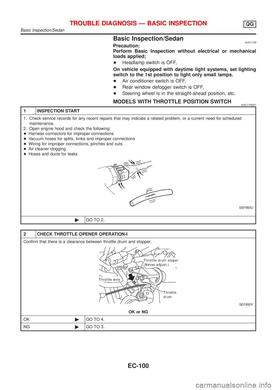
Basic Inspection/SedanNJEC1736Precaution:
Perform Basic Inspection without electrical or mechanical
loads applied;
+Headlamp switch is OFF,
On vehicle equipped with daytime light systems, set lighting
switch to the 1st position to light only small lamps.
+Air conditioner switch is OFF,
+Rear window defogger switch is OFF,
+Steering wheel is in the straight-ahead position, etc.
MODELS WITH THROTTLE POSITION SWITCHNJEC1736S01
1 INSPECTION START
1. Check service records for any recent repairs that may indicate a related problem, or a current need for scheduled
maintenance.
2. Open engine hood and check the following:
+Harness connectors for improper connections
+Vacuum hoses for splits, kinks and improper connections
+Wiring for improper connections, pinches and cuts
+Air cleaner clogging
+Hoses and ducts for leaks
SEF983U
©GO TO 2.
2 CHECK THROTTLE OPENER OPERATION-I
Confirm that there is a clearance between throttle drum and stopper.
SEF850Y
OK or NG
OK©GO TO 4.
NG©GO TO 3.
TROUBLE DIAGNOSIS Ð BASIC INSPECTIONQG
Basic Inspection/Sedan
EC-100
Page 852 of 2898
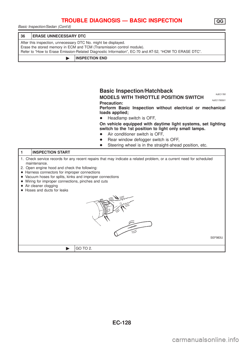
36 ERASE UNNECESSARY DTC
After this inspection, unnecessary DTC No. might be displayed.
Erase the stored memory in ECM and TCM (Transmission control module).
Refer to ªHow to Erase Emission-Related Diagnostic Informationº, EC-70 and AT-52, ªHOW TO ERASE DTCº.
©INSPECTION END
Basic Inspection/HatchbackNJEC1785MODELS WITH THROTTLE POSITION SWITCHNJEC1785S01Precaution:
Perform Basic Inspection without electrical or mechanical
loads applied;
+Headlamp switch is OFF,
On vehicle equipped with daytime light systems, set lighting
switch to the 1st position to light only small lamps.
+Air conditioner switch is OFF,
+Rear window defogger switch is OFF,
+Steering wheel is in the straight-ahead position, etc.
1 INSPECTION START
1. Check service records for any recent repairs that may indicate a related problem, or a current need for scheduled
maintenance.
2. Open engine hood and check the following:
+Harness connectors for improper connections
+Vacuum hoses for splits, kinks and improper connections
+Wiring for improper connections, pinches and cuts
+Air cleaner clogging
+Hoses and ducts for leaks
SEF983U
©GO TO 2.
TROUBLE DIAGNOSIS Ð BASIC INSPECTIONQG
Basic Inspection/Sedan (Cont'd)
EC-128
Page 868 of 2898
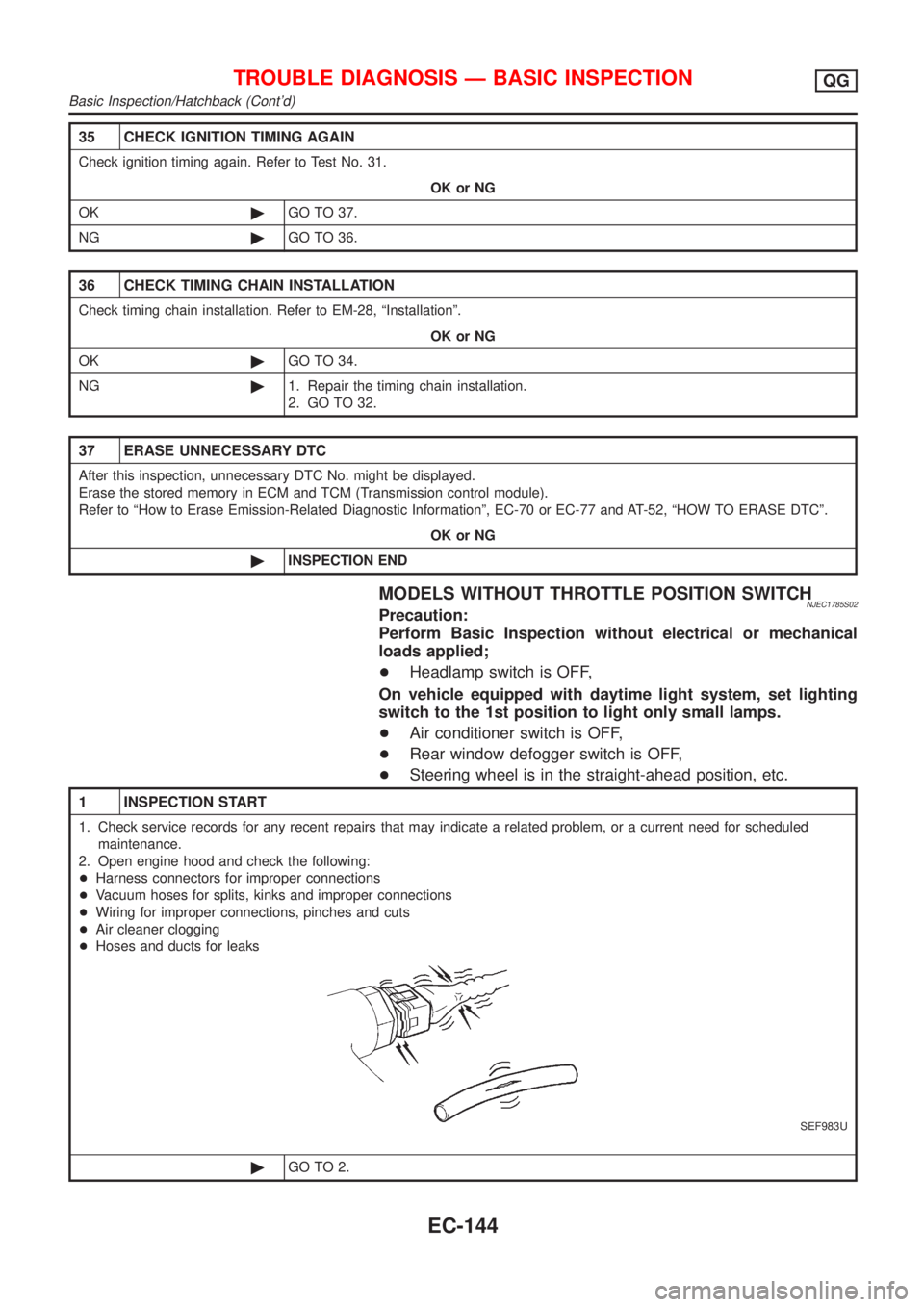
35 CHECK IGNITION TIMING AGAIN
Check ignition timing again. Refer to Test No. 31.
OK or NG
OK©GO TO 37.
NG©GO TO 36.
36 CHECK TIMING CHAIN INSTALLATION
Check timing chain installation. Refer to EM-28, ªInstallationº.
OK or NG
OK©GO TO 34.
NG©1. Repair the timing chain installation.
2. GO TO 32.
37 ERASE UNNECESSARY DTC
After this inspection, unnecessary DTC No. might be displayed.
Erase the stored memory in ECM and TCM (Transmission control module).
Refer to ªHow to Erase Emission-Related Diagnostic Informationº, EC-70 or EC-77 and AT-52, ªHOW TO ERASE DTCº.
OK or NG
©INSPECTION END
MODELS WITHOUT THROTTLE POSITION SWITCHNJEC1785S02Precaution:
Perform Basic Inspection without electrical or mechanical
loads applied;
+Headlamp switch is OFF,
On vehicle equipped with daytime light system, set lighting
switch to the 1st position to light only small lamps.
+Air conditioner switch is OFF,
+Rear window defogger switch is OFF,
+Steering wheel is in the straight-ahead position, etc.
1 INSPECTION START
1. Check service records for any recent repairs that may indicate a related problem, or a current need for scheduled
maintenance.
2. Open engine hood and check the following:
+Harness connectors for improper connections
+Vacuum hoses for splits, kinks and improper connections
+Wiring for improper connections, pinches and cuts
+Air cleaner clogging
+Hoses and ducts for leaks
SEF983U
©GO TO 2.
TROUBLE DIAGNOSIS Ð BASIC INSPECTIONQG
Basic Inspection/Hatchback (Cont'd)
EC-144