coolant NISSAN ALMERA N15 1995 Owners Manual
[x] Cancel search | Manufacturer: NISSAN, Model Year: 1995, Model line: ALMERA N15, Model: NISSAN ALMERA N15 1995Pages: 1701, PDF Size: 82.27 MB
Page 1108 of 1701
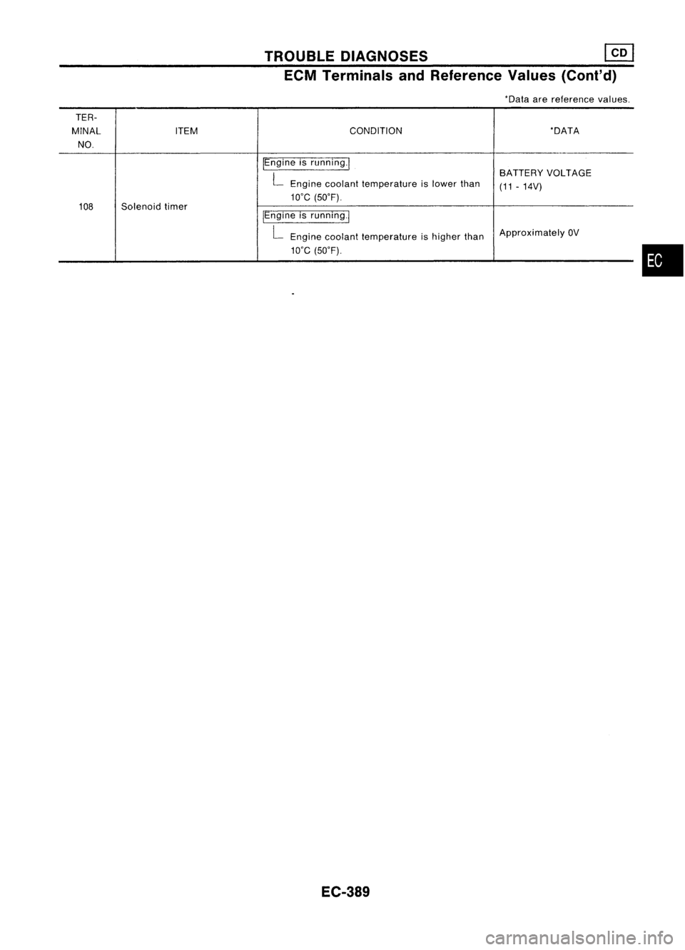
TROUBLEDIAGNOSES ~
ECM Terminals andReference Values(Cont'd)
*Data arereference values.
TER-
MINAL ITEM CONDITION
*DATA
NO.
IEngineisrunning.1
BATTERYVOLTAGE
L
Engine coolant temperature islower than
(11-14V)
we
(50'F).
108 Solenoid timer
/Engineisrunning.1
L
Engine coolant temperature ishigher than Approximately
OV
we
(50'F).
EC-389
•
Page 1109 of 1701
TROUBLEDIAGNOSES
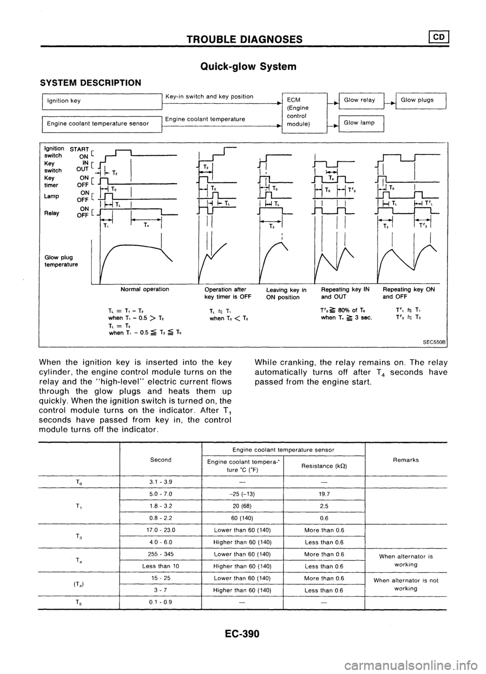
Quick-glow System
SYSTEM DESCRIPTION
Ignition key
Engine coolant temperature sensorKey-in
switch andkeyposition
Engine coolant temperature
ECM
(Engine
control
module) Glow
relay
Glow lamp Glow
plugs
Ignition START[~
~
switch
~~[ I
11
I
1iI
Key
~
switch OUT
-II-
T,
I
!
I
I-l
Key ONe
n
Hn
JTl-
.1"l....!:.1L-
~
timer
OFF
Ir1
To
I
UL
HTo
HT'o
Lamp ON
[
..Lfl
o~~
I
I-.J
TL
I
~
I
I-l
TL
I
I
I
I
I
HTL
I-l
T'L
Relay OFF
[j
I_
L-
r--L
.f"l.-.JL
~
T.
"'
II
I
II
~
1r;,1
I II I
I,
Glow plug
temperature
Normaloperation
Operationafter
key timer isOFF Leaving
keyin
ON position Repeating
keyIN
and OUT Repeating
keyON
and OFF
TL
=
T,-T,
when T,-0.5 >T,
TL
= T,
when T,-0.5 ~T,
;a;
To
TL
=.
T,
when To
<
T, T'o
~80% ofTo
when T.
5':
3sec.
T',
=.
T,
T',
=.
T,
SEC550B
When theignition keyisinserted intothekey
cylinder, theengine control module turnsonthe
relay andthe"high-level" electriccurrentflows
through theglow plugs andheats themup
quickly. Whentheignition switchisturned on,the
control module turnsonthe indicator. AfterT
1
seconds havepassed fromkeyin,the control
module turnsoffthe indicator. While
cranking, therelay remains on.The relay
automatically turnsoffafter T
4
seconds have
passed fromtheengine start.
Engine coolant temperature sensor
Second Enginecoolant tempera-' Remarks
ture 'C('F) Resistance
(kQ)
To
3.1
-3.9
- -
5.0 -7.0 -25(-13)
19.7
T,
1.8
-3.2
20(68)
2.5
0.8 -2.2 60(140)
0.6
17.0 -23.0
Lowerthan
60(140)
Morethan
0.6
T
3
40-6.0
Higherthan
60(140)
Lessthan
0.6
255 -345
Lowerthan
60(140)
Morethan
0.6
Whenalternator is
T
4
working
Less than
10
Higherthan
60(140)
Lessthan
0.6
15 -25
Lowerthan
60(140)
Morethan
0.6
Whenalternator isnot
(T
4)
working
3 -7
Higherthan
60(140)
Lessthan
0.6
T
5
0.1-0.9
- -
EC-390
Page 1110 of 1701
TROUBLEDIAGNOSES
Quick-glow System(Cont'd)
DESCRIPTION
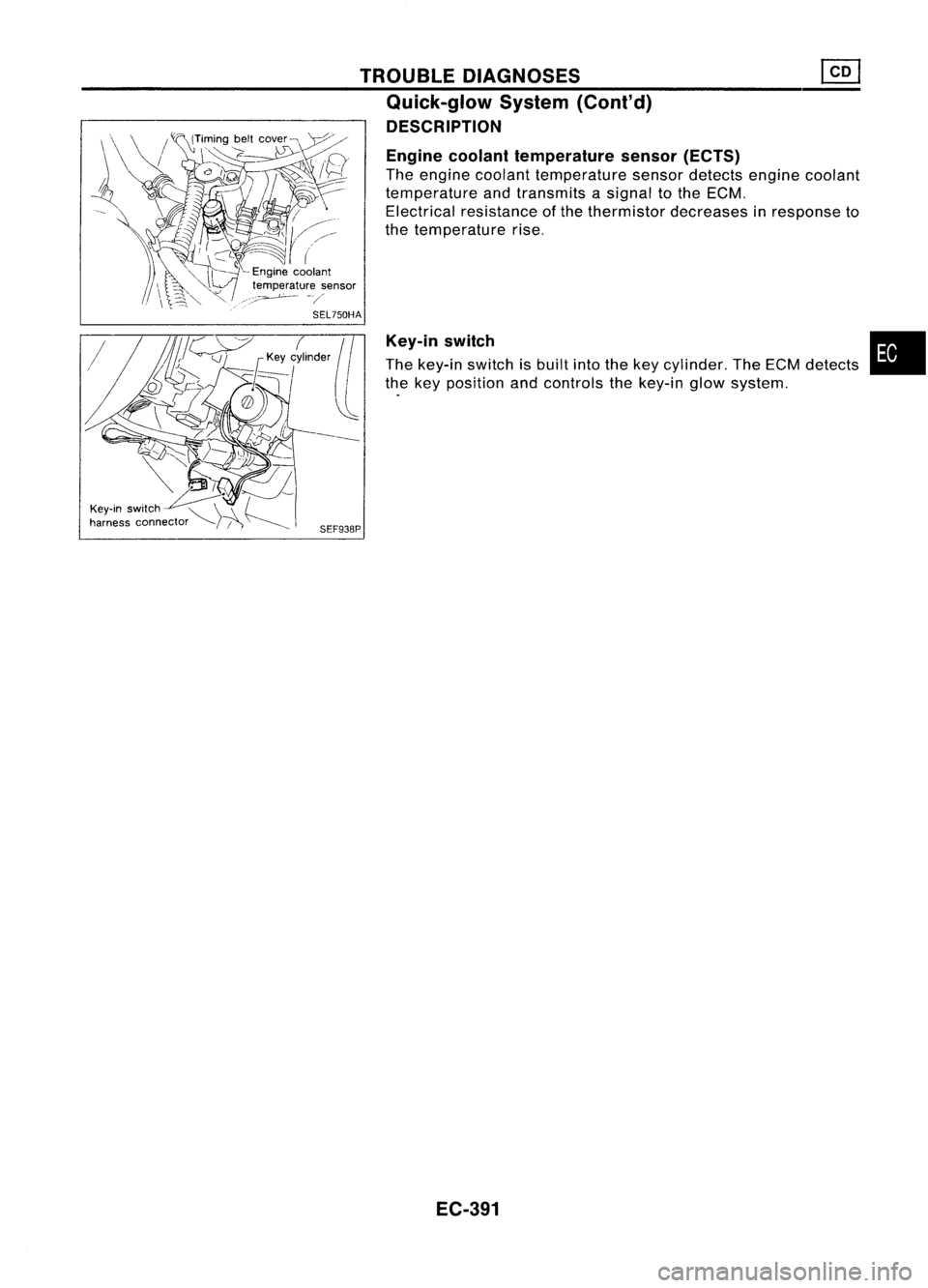
Engine coolant temperature sensor(ECTS)
The engine coolant temperature sensordetects enginecoolant
temperature andtransmits asignal tothe ECM.
Electrical resistance ofthe thermistor decreases inresponse to
the temperature rise.
Key-in switch
The key-in switch isbuilt intothekey cylinder. TheECM detects
the key position andcontrols thekey-in glowsystem.
SEF938P
EC-391
•
Page 1111 of 1701
![NISSAN ALMERA N15 1995 Owners Manual TROUBLEDIAGNOSES
Quick-glow System(Cont'd)
EC-GLOW-01
IGNITION SWITCH IGNITIONSWITCH
START ONorSTART
7.5A
1261
10A
1251
10A
IT]
FUSE
BLOCK
(JIB)
@:ID
Refer
toEL-POWER.
<I>:
LHDmodels](/img/5/57349/w960_57349-1110.png "NISSAN ALMERA N15 1995 Owners Manual TROUBLEDIAGNOSES
Quick-glow System(Cont'd)
EC-GLOW-01
IGNITION SWITCH IGNITIONSWITCH
START ONorSTART
7.5A
1261
10A
1251
10A
IT]
FUSE
BLOCK
(JIB)
@:ID
Refer
toEL-POWER.
<I>:
LHDmodels")
TROUBLEDIAGNOSES
Quick-glow System(Cont'd)
EC-GLOW-01
IGNITION SWITCH IGNITIONSWITCH
START ONorSTART
7.5A
1261
10A
1251
10A
IT]
FUSE
BLOCK
(JIB)
@:ID
Refer
toEL-POWER.
:
LHDmodels
<£D:
RHOmodels
ECM
(ENGINECONTROL
MODULE)
@
TW
~
G/B
I
Toengine coolant
-------.. temperaturesensor
(Refer toEC-COOL/F.)
1I~11
Y
I
Y
I!i
COMBINATION
METER
(GLOW LAMP)
11
3•3
1
@
OR
I
OR
m
GIL
1Ni91
BR
BR
~
IGN
1Ni91
BR
BR
~
IGN
IN.41
B/Y
GNO-C GNO-C GNO-AGNO-A
12.6
I 11
3•9
I
11~11 11~51
B BB B
I
II I
----.-_-.- __1.
I
.-o-ee-°l
I
<;
A
;>
B
1---.1
B
-!-! .-!-
B/Y
~
START
Refertolast page
(Foldout page).
HEC088
EC-392
Page 1114 of 1701
TROUBLEDIAGNOSES
Quick-glow System(Cont'd)
@
CHECK COMPONENTS NG
(Glow relay, Glowplug,Engine coolant
temperature sensor,Key-inswitch, Igni-
tion switch).
Refer to"Component Inspection"(EC-
397).
OK
Disconnect andreconnect harnesscon-
nectors inthe circuit. Thenretest.
Trouble isnot fixed.
Check ECMpinterminals fordamage or
the connection ofECM harness connec-
tor. Reconnect ECMharness connector
and retest. Replace
malfunctioning
component(s).
•
BATIERY [
Voltage
OV
Ignition
key
START
[
ON
IN [
OUT
,
,
,
I
,
JL
SEC5558SYSTEM
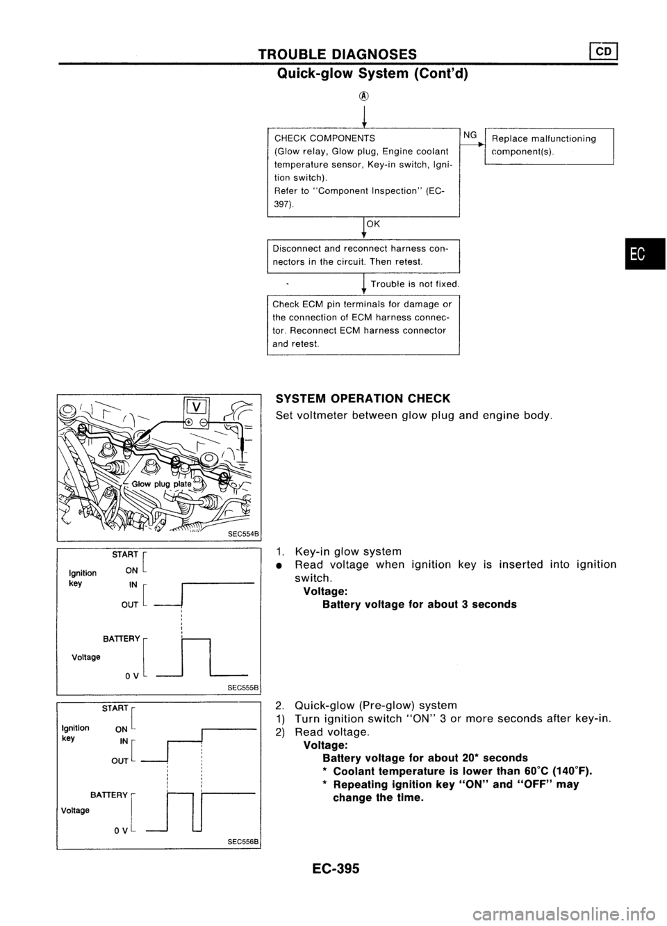
OPERATION CHECK
Set voltmeter betweenglowplugandengine body.
1. Key-in glowsystem
• Read voltage whenignition keyisinserted intoignition
switch.
Voltage: Battery voltage forabout 3seconds
Ignition
key
BATIERY [
Voltage
OV
SEC5568
2.
Quick-glow (Pre-glow)system
1) Turn ignition switch"ON"3or more seconds afterkey-in.
2) Read voltage.
Voltage: Battery voltage forabout 20*seconds
*
Coolant temperature islower than60°C(140°F).
* Repeating ignitionkey"ON" and"OFF" may
change thetime.
EC-395
Page 1115 of 1701
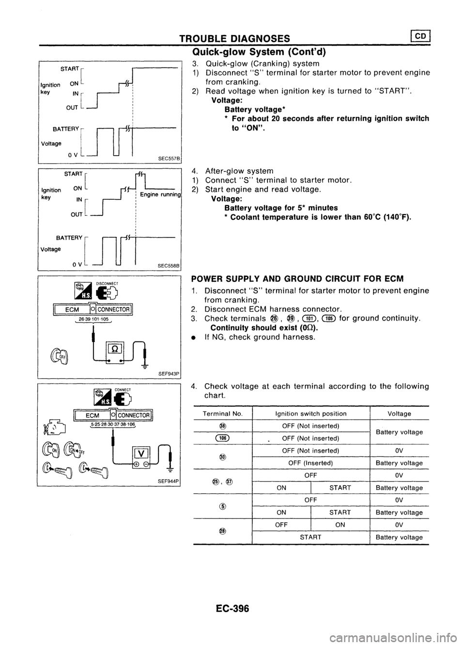
4.After-glow system
1) Connect "8"terminal tostarter motor.
2) Start engine andread voltage.
Voltage: Battery voltage for5*minutes
* Coolant temperature islower than60°C(140°F).
TROUBLE
DIAGNOSES
Quick-glow System(Cont'd)
3. Quick-glow (Cranking)system
1) Disconnect "S"terminal forstarter motortoprevent engine
from cranking.
2) Read voltage whenignition keyisturned to"8T ART".
Voltage: Battery voltage
*
*
For about 20seconds afterreturning ignitionswitch
to
"ON".
START
[
J
Ignition ON
F:
key IN
r- j
OUT
L :
I
I
I
vo,,:TIERYlJlfr
o
V
SEC557B
STA:~[
JL
Ignition
r:
Enginerunning
key IN :
OUT [
!
I
I
,
I
,
votta;ATIERY [Jlfi=
o
V
SEC558B
~i5
II
ECM E
CONNECTOR
II
26-39101-105 POWER
SUPPLY ANDGROUND CIRCUITFORECM
1. Disconnect "S"terminal forstarter motortoprevent engine
from cranking.
2. Disconnect ECMharness connector.
3. Check terminals
@,
@.
Gill.
@
forground continuity.
Continuity shouldexist(On).
• IfNG, check ground harness.
SEF943P
(D
II
~i5
ECM B
CONNECTOR
II
• 5-25-28-30-37-38-106,
4.
Check voltage ateach terminal according tothe following
chart.
Terminal No. Ignitionswitchposition
Voltage
@
OFF(Notinserted)
GID
Battery
voltage
.
OFF
(Notinserted)
OFF (Not inserted) OV
@
OFF(Inserted) Batteryvoltage
OFF OV
@,@
ONSTARTBatteryvoltage
OFF OV
@
ONSTART
Batteryvoltage
OFF ONOV
@
STARTBatteryvoltage
EC-396
Page 1117 of 1701
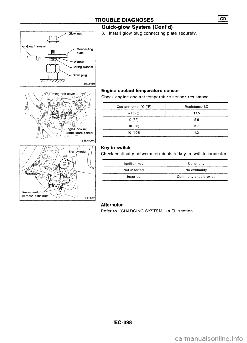
SEC5658Enginecoolant temperature sensor
Check engine coolant temperature sensorresistance.
Key-in switch
Check continuity betweenterminals ofkey-in switch connector.
11.5
5.6
3.7
1.2
Resistance
kfl
Continuity
No continuity
Continuity shouldexist.
Ignition
key
Not inserted
Inserted
Coolant
temp.°C('F)
-15 (5)
0(32)
10 (50)
40 (104)
TROUBLE
DIAGNOSES
Quick-glow System(Cont'd)
3. Install glowplugconnecting platesecurely.
Connecting
plate
Spring washer
~GIOwnut
Glow harness
Alternator
Refer to"CHARGING SYSTEM"inEL section.
EC-398
Page 1118 of 1701
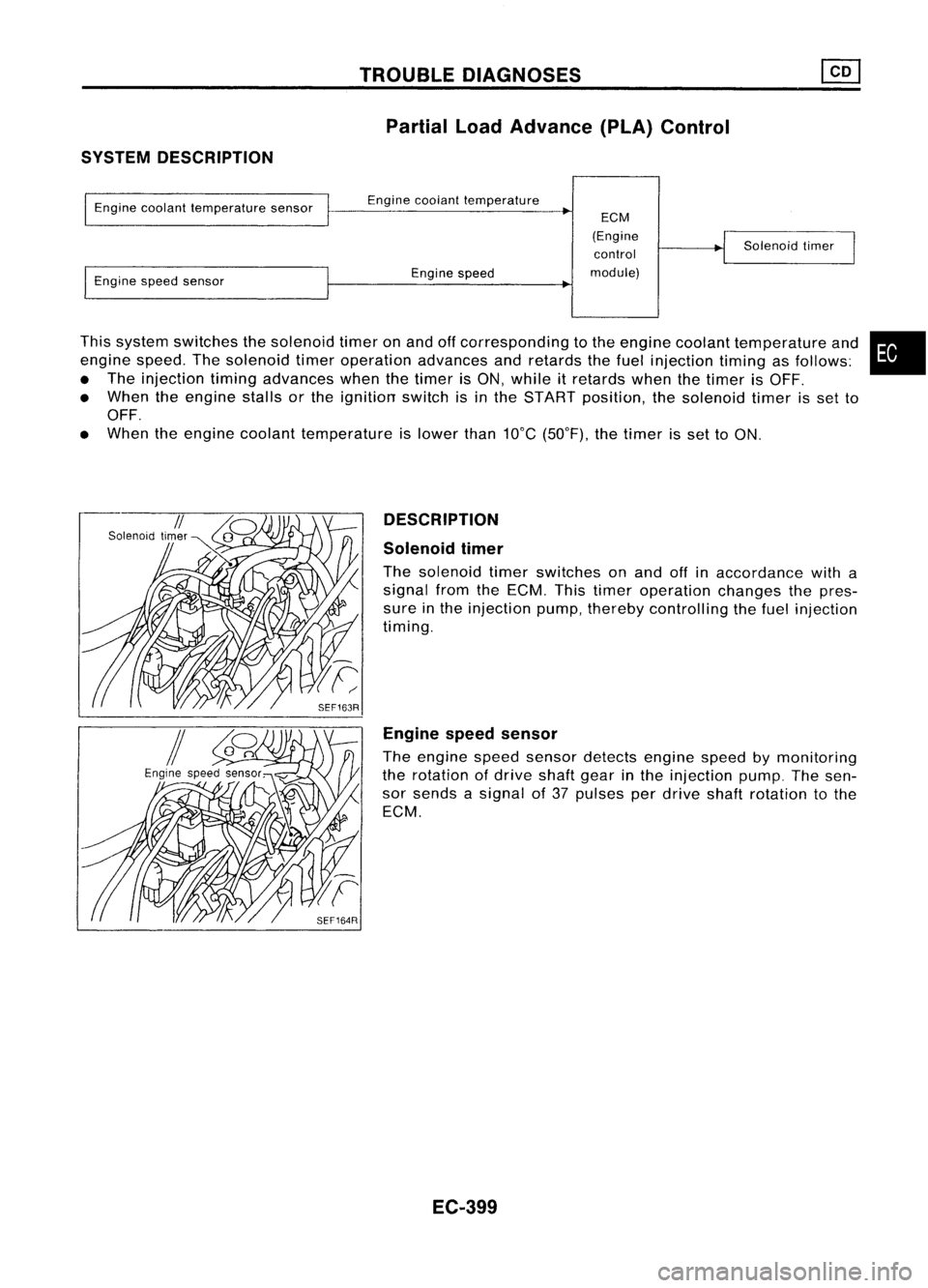
SYSTEMDESCRIPTION TROUBLE
DIAGNOSES
Partial LoadAdvance (PLA)Control
This system switches thesolenoid timeronand offcorresponding tothe engine coolant temperature and
engine speed.Thesolenoid timeroperation advancesandretards thefuel injection timingasfollows:
• The injection timingadvances whenthetimer isON, while itretards whenthetimer isOFF.
• When theengine stallsorthe ignition switchisin the START position, thesolenoid timerisset to
OFF.
• When theengine coolant temperature islower than10°C(50°F), thetimer isset toON.
Engine
coolant temperature sensor
Engine speedsensor Engine
coolant temperature
Engine speed
ECM
(Engine control
module) Solenoid
timer
•
DESCRIPTION
Solenoid timer
The solenoid timerswitches onand offinaccordance witha
signal fromtheECM. Thistimer operation changesthepres-
sure inthe injection pump,thereby controlling thefuel injection
timing.
Engine speedsensor
The engine speedsensor detects enginespeedbymonitoring
the rotation ofdrive shaftgearinthe injection pump.Thesen-
sor sends asignal of37 pulses perdrive shaftrotation tothe
ECM.
EC-399
Page 1119 of 1701
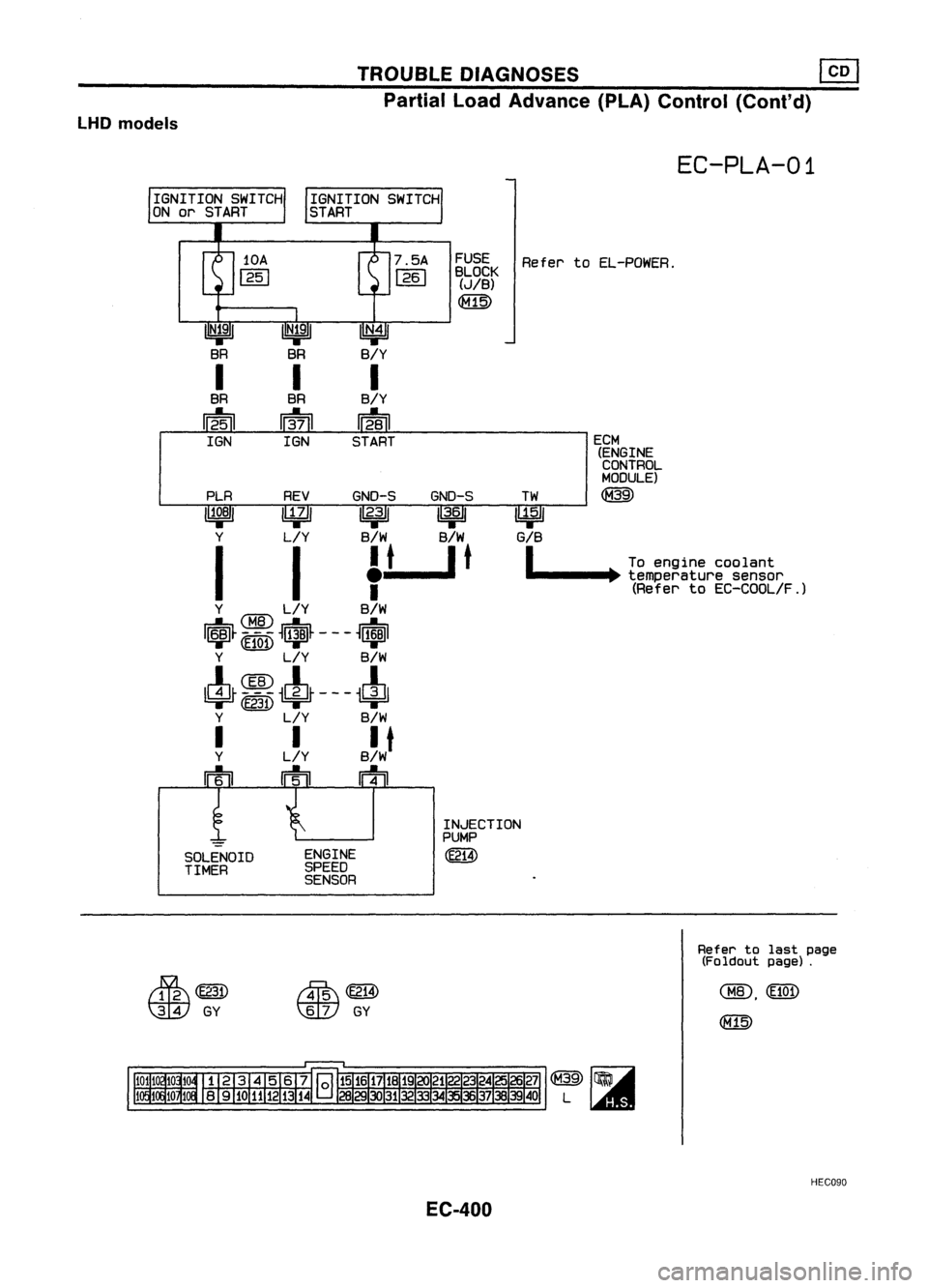
TROUBLEDIAGNOSES ~
Partial LoadAdvance (PLA)Control (Cont'd)
LHD models
EC-PLA-01
~~~~K RefertoEL-POWER.
(JIB)
PLR REVGND-S GND-S
11~81 ~
/12.3
11
13.61
Y L!Y B/W B/W
I
I
f-
t
_I
t
Y ~ L!Y B!W
IrlsJ~ -
M.-B -
~I&~ ---
~r;]ID1
'T'
(E101)
L:jf'
"T'
Y L!Y B!W
1c!J~ ~
~cL~ ---
~c!J1
<=j=
(E231)
=r' =r'
Y L!Y B!W
!
L~Y B~Wt
rrh
m m
ECM
(ENGINECONTROL
MODULE)
@
TW
~
G!B
1
Toengine coolant
._--~. temperature sensor
(Refer toEC-COOL!F.)
II
N•4
1
B/Y
I
B/Y
Iffsn
START
IN;91
BR
I
BR
~
IGN
SOLENOID
TIMER ENGINE
SPEED
SENSOR INJECTION
PUMP
(E214)
~~
~ GY
~
(E214)
\ill)
GY
Refer
tolast page
(Foldout page).
HEC090
EC-400
Page 1120 of 1701

TROUBLEDIAGNOSES ~
Partial LoadAdvance (PLA)Control (Cont'd)
RHO models
EC-PLA-02
FUSE RefertoEL-POWER.
BLOCK
(JIB)
~
PLR REVGND-S GND-S
11~BI ~
11
2•3113.,61
Y L/Y B/wB/W
I
I
f-
t-,t
Y ~ L/Y B/W
I$t _M~-
~t~ -- -
~$I
~
Y L/Y B/W
4r=~~t---~
Y L/Y B/W
!
L~Y B~Wt
m mrn
ECM
(ENGINE
CONTROL
MODULE)
~
•
TW
~
G/B
I
Toengine coolant
.......... ~.temperature sensor
(Refer toEC-COOL/F.)
IN.41
B/Y
I
B/Y
Wail
START
IN;91
BR
I
BR
~
IGN
SOLENOID
TIMER ENGINE
SPEED
SENSOR INJECTION
PUMP
(E214)
Refertolast page
(Foldout page).
~(E203)
rn:rn:tIlID
GY
M\
(~!4)
t:]lV
GY
HECC91
EC-401