coolant NISSAN ALMERA N15 1995 Service Manual
[x] Cancel search | Manufacturer: NISSAN, Model Year: 1995, Model line: ALMERA N15, Model: NISSAN ALMERA N15 1995Pages: 1701, PDF Size: 82.27 MB
Page 1160 of 1701
A16-21
N.m ~/
(1.6 •2.1 kg-m,
12 -15
ft.lb)
ENGINE
COOLING SYSTEM
Cooling SystemInspection (Cont'd)
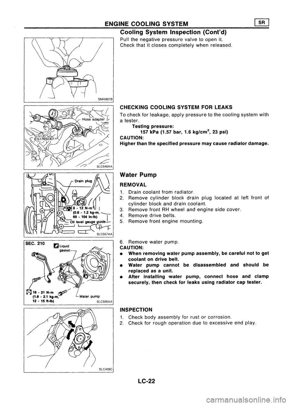
Pull thenegative pressure valvetoopen it.
Check thatitcloses completely whenreleased.
CHECKING COOLINGSYSTEMFORLEAKS
To check forleakage, applypressure tothe cooling systemwith
a tester.
Testing pressure:
157 kPa (1.57 bar,1.6kg/cm
2,
23psi)
CAUTION:
Higher thanthespecified pressuremaycause radiator damage.
Water Pump
REMOVAL
1. Drain coolant fromradiator.
2. Remove cylinderblockdrain pluglocated atleft front of
cylinder blockanddrain coolant.
3. Remove frontRHwheel andengine sidecover.
4. Remove drivebelts.
5. Remove frontengine mounting.
6. Remove waterpump.
CAUTION:
• When removing waterpumpassembly, becareful nottoget
coolant ondrive belt.
• Water pumpcannot bedisassembled andshould be
replaced asaunit.
• After installing -waterpump, connect hoseandclamp
securely, thencheck forleaks using radiator captester.
INSPECTION
1. Check bodyassembly forrust orcorrosion.
2. Check forrough operation duetoexcessive endplay.
SLC408C LC-22
Page 1162 of 1701
ENGINECOOLING SYSTEM ~
Thermostat
(Cont'd)
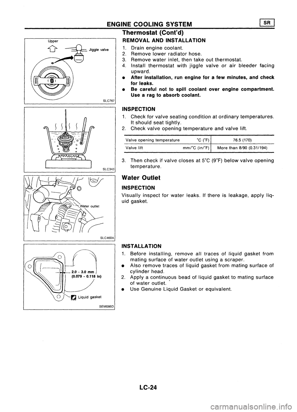
Upper REMOVALANDINSTAllATION
;::g=
Jigglevalve
1.Drain engine coolant.
2. Remove lowerradiator hose.
3. Remove waterinlet,thentake outthermostat.
4. Install thermostat withjiggle valveorair bleeder facing
upward.
• After installation, runengine forafew minutes, andcheck
for leaks.
• Becareful nottospill coolant overengine compartment.
Use arag toabsorb coolant.
SLC767
INSPECTION
1. Check forvalve seating condition atordinary temperatures.
It
should seattightly.
2. Check valveopening temperature andvalve lift.
Valve opening temperature
°c
(OF) 76.5(170)
Valve lift mmrC(inrF) Morethan
8/90(0.31/194)
3. Then check ifvalve closes at5°C (9°F) below valveopening
temperature.
Water Outlet
INSPECTION
Visually inspectforwater leaks.
If
there isleakage, applyliq-
uid gasket.
SLC460A INSTAllATION
1. Before installing, removealltraces ofliquid gasket from
mating surface ofwater outlet usingascraper.
• Also remove tracesofliquid gasket frommating surface of
cylinder head.
2. Apply acontinuous beadofliquid gasket tomating surface
of water outlet. .
• Use Genuine LiquidGasket orequivalent.
~ Liquid gasket
SEM086D
LC-24
Page 1163 of 1701
SEC.214
10
ENGINE
COOLING SYSTEM
Radiator
SLC039BA
•
CD
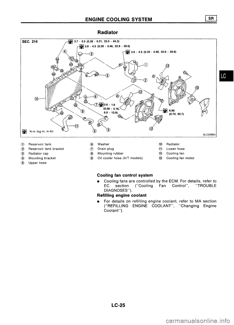
Reservoir tank
@
Reservoir tankbracket
@
Radiator cap
@
Mounting bracket
CID
Upper hose
@
Washer
(J)
Drain plug
CID
Mounting rubber
@
Oilcooler hose
(AfT
models)
@)
Radiator
@
Lower hose
@
Cooling fan
@
Cooling fanmotor
Cooling fancontrol system
• Cooling fansarecontrolled bythe ECM. Fordetails, referto
EC section ("Cooling FanControl", "TROUBLE
DIAGNOSES").
Refilling enginecoolant
• For details onrefilling enginecoolant, refertoMA section
("REFILLING ENGINECOOLANT", "ChangingEngine
Coolant").
LC-25
Page 1165 of 1701
ENGINELUBRICATION SYSTEM
SLC926.A Ifdifference isextreme, checkoilpassage andoilpump foroil
leaks.
6. Install oilpressure switchwithsealant.
ST25052000
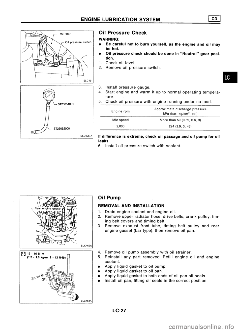
3.
Install pressure gauge.
4. Start engine andwarm itup tonormal operating tempera-
ture.
5 .. Check oilpressure withengine running underno-load.
•
Approximate dischargepressure
kPa (bar,
kg/cm
2,
psi)
More than59(0.59, 0.6,9)
294 (2.9, 3,43)
Idle
speed
2,000
Engine
rpm
Oil
Pressure Check
WARNING: • Becareful nottoburn yourself, asthe engine andoilmay
be hot.
• Oilpressure checkshould bedone in"Neutral" gearposi-
tion.
1. Check oillevel.
2. Remove oilpressure switch.
SLC461
Oil
pressure switch
ST25051 001
~ 12.16 N.m
(1.2 .1.6 kg-m, 9-
12 ft.lb) SLC462A
SLC463A Oil
Pump
REMOVAL ANDINSTAllATION
1. Drain engine coolant andengine oil.
2. Remove upperradiator hose,drivebelts, crank pulley, tim-
ing belt covers andtiming belt.
3. Remove exhaustfronttube, timing beltpulley andrear
engine gusset(bartype), thenremove oilpan.
4. Remove oilpump assembly withoilstrainer.
5. Reinstall anypart removed. Refillengine oiland engine
coolant.
• Apply liquidgasket tooil pump.
• Apply liquidgasket tooil pan.
• Apply liquidgasket toboth ends ofoil pan oilseals.
• Install oilpan, fitting oilseals inthe correct position.
LC-27
Page 1168 of 1701
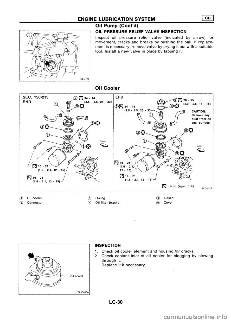
ENGINELUBRICATION SYSTEM
Oil Pump (Cont'd)
OIL PRESSURE RELIEFVALVEINSPECTION
Inspect oilpressure reliefvalve (indicated byarrow) for
movement, cracksandbreaks bypushing theball. Ifreplace-
ment isnecessary, removevalvebyprying itout with asuitable
tool. Install anew valve inplace bytapping it.
SLC446 OilCooler
SEC. 150-213
RHO
tOJ
16-21
(1.6. 2.1,12•15)
/
tOJ
34-44
11 ~
f:1
(3.5 -4.5, 25-33)
Front ~ LHO
:N.m (kg-m, ft-Ib)
Front
~
SLC047B
CD
Oilcooler
@
Connector
@
a-ring
@
Oilfilter bracket
@
Gasket
@
Cover
INSPECTION
1. Check oilcooler element andhousing forcracks.
2. Check coolant inletofoil cooler forclogging byblowing
through it.
Replace itifnecessary.
Oil cooler
SLC465A LC-30
Page 1171 of 1701
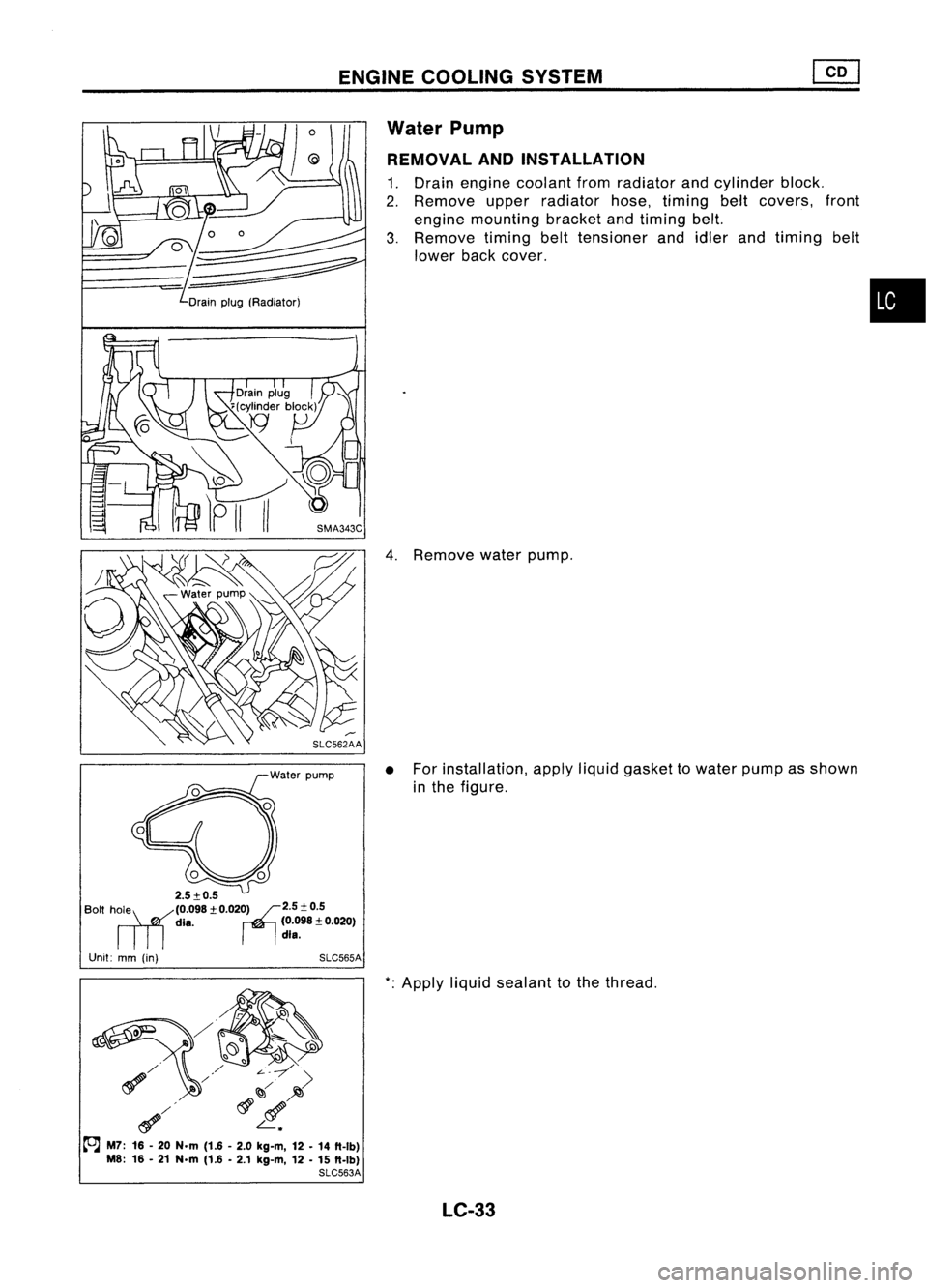
ENGINECOOLING SYSTEM
Water Pump
REMOVAL ANDINSTALLATION
1. Drain engine coolant fromradiator andcylinder block.
2. Remove upperradiator hose,timing beltcovers, front
engine mounting bracketandtiming belt.
3. Remove timingbelttensioner andidler andtiming belt
lower backcover.
~
Drain plug(Radiator)
4.Remove waterpump.
• For installation, applyliquidgasket towater pumpasshown
in the figure.
2.5:!:0.5
Bolt hRille (0.098:!:0.020r12.5:!: 0.5
die. (0.098:!:0.020)
dIe.
Unit: mm(in) SLC565A
*:
Apply liquidsealant tothe thread.
~/ ~~;>
~/ ~l!.
to.J
M7: 16-20 N.m (1.6-2.0 kg-m, 12-14 ft-Ib)
M8: 16-21 N.m (1.6-2.1 kg-m, 12-15 ft-Ib)
SLC563A
LC-33
•
Page 1174 of 1701
ENGINECOOLING SYSTEM
@J
Radiator (Cont'd)
Cooling fancontrol system
• Cooling fansarecontrolled bythe ECM. Fordetails, referto
EC section
("Cooling
FanControl", "TROUBLE
DIAGNOSES").
Refilling enginecoolant
• For details onrefilling enginecoolant, refertoMA section
("REFILLING ENGINECOOLANT", "ChangingEngine
Coolant").
LC-36
Page 1182 of 1701
Innerside
SEM164F PRECAUTIONS
Parts Requiring AngularTightening
• Use anangle wrench forthe final tightening ofthe follow-
ing engine parts:
(1) Cylinder headbolts
(2) Main bearing capbolts (SRengine only)
(3) Connecting rodcap nuts (SRand CDengine)
• Donot use atorque valueforfinal tightening. •
• The torque values forthese partsareforapreliminary step.
• Ensure threadandseat surfaces areclean andcoated with
engine oil.
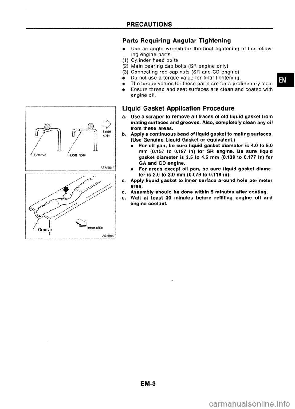
Liquid Gasket Application Procedure
a. Use ascraper toremove alltraces ofold liquid gasket from
mating surfaces andgrooves. Also,completely cleananyoil
from these areas.
b. Apply acontinuous beadofliquid gasket tomating surfaces.
(Use Genuine LiquidGasket orequivalent.)
• For oilpan, besure liquid gasket diameter is4.0 to5.0
mm (0.157 to0.197 in)for SR engine. Besure liquid
gasket diameter is3.5 to4.5 mm (0.138 to0.177 in)for
GA and CDengine.
• For areas except oilpan, besure liquid gasket diame-
ter is2.0 to3.0 mm (0.079 to0.118 in).
c. Apply liquidgasket toinner surface aroundholeperimeter
area.
d. Assembly shouldbedone within 5minutes aftercoating.
e. Wait atleast 30minutes beforerefilling engineoiland
engine coolant.
EM.3
Page 1189 of 1701
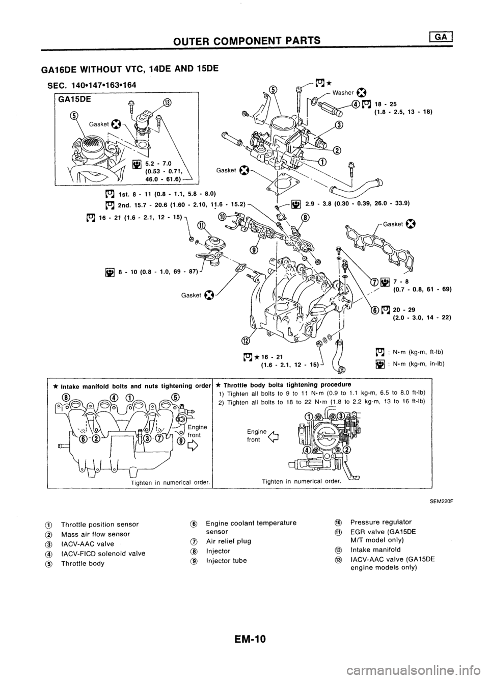
OUTERCOMPONENT PARTS
tOJ:
N.m (kg-m, ft-Ib)
iii :
N'm (kg-m, in-Ib)
Tighten innumerical order.
Engine
A
Iront
y
*
Throttle bodyboltstightening procedure
1) Tighten allbolts to9to 11 N.m (0.9 to
1.1
kg-m, 6.5to8.0 fl-Ib)
2) Tighten allbolts to18 to22 N'm (1.8to2.2 kg-m, 13to16 ft-Ib)
Tighten innumerical order.
GA16DE
WITHOUT VTe,14DE AND15DE
SEC. 140-147-163-164
GA15DE
SEM220F
CD
Throttle position sensor
@ Mass airflow sensor
@
IACV-AAC valve
@ IACV-FICD solenoidvalve
@ Throttle body @
Engine coolant temperature
sensor
IJ)
Airrelief plug
@
Injector
@ Injector tube
@l
Pressure regulator
@
EGR valve (GA15DE
M/T
model only)
@ Intake manifold
@ IACV-AAC valve(GA15DE
engine models only)
EM-10
Page 1199 of 1701
TIMINGCHAIN
Without
VTC
CAUTION:
• After removing timingchain,donot turn crankshaft and
camshaft separately, orvalves willstrike piston heads.
• When installing camshafts, chaintensioner, oilseals, or
other sliding parts,lubricate contacting surfaceswithnew
engine oil.
• Apply newengine oiltobolt threads andseat surfaces when
installing cylinderhead,camshaft sprocket,crankshaft
pulley, andcamshaft brackets.
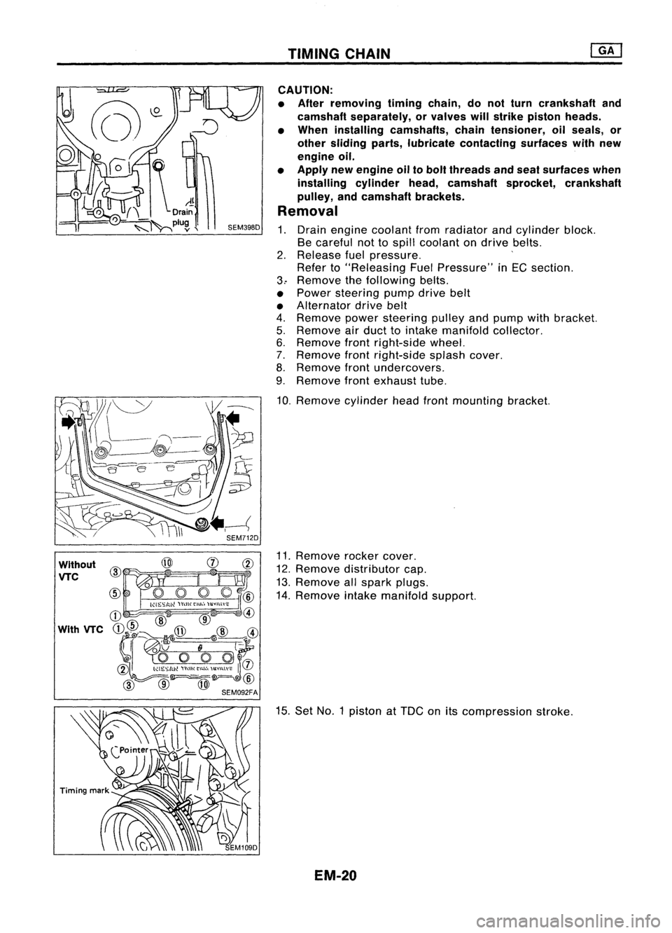
Removal
1. Drain engine coolant fromradiator andcylinder block.
Be careful nottospill coolant ondrive belts.
2. Release fuelpressure. '
Refer to"Releasing FuelPressure" inEG section.
3.. Remove thefollowing belts.
• Power steering pumpdrivebelt
• Alternator drivebelt
4. Remove powersteering pulleyandpump withbracket.
5. Remove airduct tointake manifold collector.
6. Remove frontright-side wheel.
7. Remove frontright-side splashcover.
8. Remove frontundercovers.
9. Remove frontexhaust tube.
10. Remove cylinderheadfrontmounting bracket.
11. Remove rockercover.
12. Remove distributor cap.
13. Remove allspark plugs.
14. Remove intakemanifold support.
15. Set NO.1 piston at
TOG
onitscompression stroke.
EM-20