sensor NISSAN ALMERA N15 1995 Service Manual
[x] Cancel search | Manufacturer: NISSAN, Model Year: 1995, Model line: ALMERA N15, Model: NISSAN ALMERA N15 1995Pages: 1701, PDF Size: 82.27 MB
Page 1368 of 1701
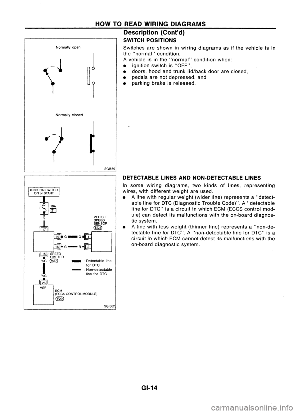
Normallyopen
HOW
TOREAD WIRING DIAGRAMS
Description (Cont'd)
SWITCH POSITIONS
Switches areshown inwiring diagrams asifthe vehicle isin
the "normal" condition.
A vehicle isin the "normal" conditionwhen:
• ignition switchis"OFF",
• doors, hoodandtrunk lid/back doorareclosed,
• pedals arenotdepressed, and
• parking brakeisreleased.
Normally closed
5GI860DETECTABLE LINESANDNON-DETECTABLE LINES
In some wiring diagrams, twokinds oflines, representing
wires, withdifferent weightareused.
• Aline with regular weight(widerline)represents a"detect-
able lineforDTC (Diagnostic TroubleCode)".A"detectable
line forDTC" isacircuit inwhich ECM(ECCS control mod-
ule) candetect itsmalfunctions withtheon-board diagnos-
tic system.
• Aline with lessweight (thinner line)represents a"non-de-
tectable lineforDTC", A"non-detectable lineforDTC" isa
circuit inwhich ECMcannot detectitsmalfunctions withthe
on-board diagnostic system.
SGI862
_
:Detectable line
for DTC
- :Non-detectable
line forDTC
Y
~ VEHICLE
SPEED SENSOR
@
lill-G_G~
llli-G-R~
I~I
SPEED
.,=
OMETER
Y/G
@Z)
I
Y/G
[]26
VSP ECM
(ECCS CONTROL MODULE)
@)
GI-14
Page 1371 of 1701
HOWTOREAD WIRING DIAGRAMS
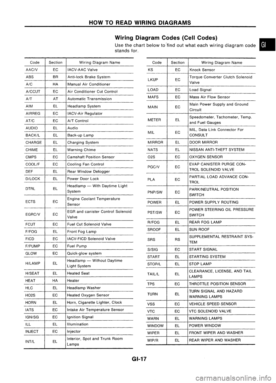
Wiring Diagram Codes(CellCodes)
Use thechart below to'find outwhat each wiring diagram code•
stands for,
Code Section WiringDiagram Name
AACIV ECIACV-AAC
Valve
ABS BR
Anti-lock BrakeSystem
A/C HAManualAirConditioner
A/CCUT ECAir
Conditioner CutControl
A/T ATAutomatic Transmission
AIM ELHeadlamp System
AIRREG ECIACV-Air Regulator
AT/C ECA/TControl
AUDIO ELAudio
BACK/L ELBack-up Lamp
CHARGE ELCharging System
CHIME ELWarning Chime
CMPS EC
Camshaft PositionSensor
COOllF ECCooling
FanControl
DEF ELRearWindow Defogger
D/LOCK ELPowerDoorLock
DTRL ELHeadlamp
-With Daytime Light
System
ECTS ECEngine
Coolant Temperature
Sensor
EGR andcanister ControlSolenoid
EGRCIV EC
Valve
FCUT ECFuel
CutSolenoid Valve
F/FOG ELFront
FogLamp
FICO ECIACV-FICD
SolenoidValve
F/PUMP ECFuel
Pump
GLOW ECQuick-glow
system
H/LAMP ELHeadlamp
-Without Daytime
Light System
H/SEAT ELHeated
Seat
HEAT HA
Heater
HLC ELHeadlamp
Washer
H02S ECHeated
Oxygen Sensor
HORN ELHorn,
Cigarette Lighter,Clock
IATS ECIntake
AirTemperature Sensor
IGN/SG ECIgnition
Signal
ILL ELIllumination
INJECT ECInjector
INT/L ELInterior,
SpotandTrunk Room
Lamps Code
Section WiringDiagram Name
KS ECKnock
Sensor
LKUP ECTorque
Converter ClutchSolenoid
Valve
LOAD ECLoadSignal
MAFS ECMass
AirFlow Sensor
MAIN ECMain
Power Supply andGround
Circuit
METER ELSpeedometer,
Tachometer,Temp.
and Fuel Gauges
MIL ECMIL,
Data LinkConnector For
CONSULT
MIRROR ELDOOR
MIRROR
NATS ELNISSAN
ANTI-THEFT SYSTEM
02S ECOXYGEN
SENSOR
EC EVAP
CANISTER PURGECON-
PGCIV TROLSOLENOID VALVE
PLA ECPARTIAL
LOADADVANCE CON-
TROL
EC PARK/NEUTRAL
POSITION
PNP/SW SWITCH
POWER ELPOWER
SUPPLY ROUTING
POWER STEERING OILPRESSURE
PST/SW EC
SWITCH
R/FOG ELREAR
FOGLAMP
SROOF ELSUN
ROOF
SUPPLEMENTAL RESTRAINTSYS-
SRS RS
TEM
S/SIG ECST
ART SIGNAL
START ELSTARTING
SYSTEM
STOP/L ELSTOP
LAMP
TAllIL ELCLEARANCE,
LICENSE,ANDTAIL
LAMPS
TPS ECTHROTTLE
POSITIONSENSOR
TURN SIGNAL ANDHAZARD
TURN EL
WARNING LAMPS
VSS ECVEHICLE
SPEEDSENSOR
VTC ECVTC
SOLENOID VALVE
WARN ELWARNING
LAMPS
WINDOW ELPOWER
WINDOW
WIPER ELFRONT
WIPERANDWASHER
WIP/R ELREAR
WIPER ANDWASHER
GI-17
Page 1373 of 1701
HOWTOPERFORM EFFICIENT DIAGNOSIS FORANELECTRICAL INCIDENT
Incident Simulation Tests
INTRODUCTION
Sometimes thesymptom isnot present whenthevehicle isbrought infor service.
If
possible, re-create
the conditions presentatthe time ofthe incident. Doingsomay help avoid aNo Trouble FoundDiag-
nosis. Thefollowing sectionillustrates waystosimulate theconditionslenvironment underwhich the
owner experiences anelectrical incident.
The section isbroken intothesixfollowing topics:
• Vehicle vibration
• Heat sensitive
• Freezing
• Water intrusion
• Electrical load
• Cold orhot start up
Get athorough description ofthe incident fromthecustomer. Itis important forsimulating thecondi-
tions ofthe problem.
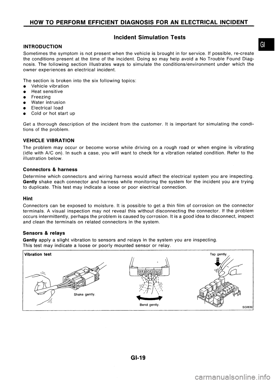
VEHICLE VIBRATION
The problem mayoccur orbecome worsewhiledriving onarough roadorwhen engine isvibrating
(idle with
AIC
on). Insuch acase, youwillwant tocheck foravibration relatedcondition. Refertothe
illustration below.
Connectors
&
harness
Determine whichconnectors andwiring harness wouldaffecttheelectrical systemyouareinspecting.
Gently
shakeeachconnector andharness whilemonitoring thesystem forthe incident youaretrying
to duplicate. Thistestmay indicate aloose orpoor electrical connection.
Hint
Connectors canbeexposed tomoisture. Itis possible toget athin film ofcorrosion onthe connector
terminals. Avisual inspection maynotreveal thiswithout disconnecting theconnector. Ifthe problem
occurs intermittently, perhapstheproblem iscaused bycorrosion. Itis agood ideatodisconnect, inspect
and clean theterminals onrelated connectors inthe system.
Sensors
&
relays
Gently
applyaslight vibration tosensors andrelays inthe system youareinspecting.
This testmay indicate aloose orpoorly mounted sensororrelay.
•
Vibration test
Bendgently.
GI-19
Tap
gently.
8GI839
Page 1383 of 1701
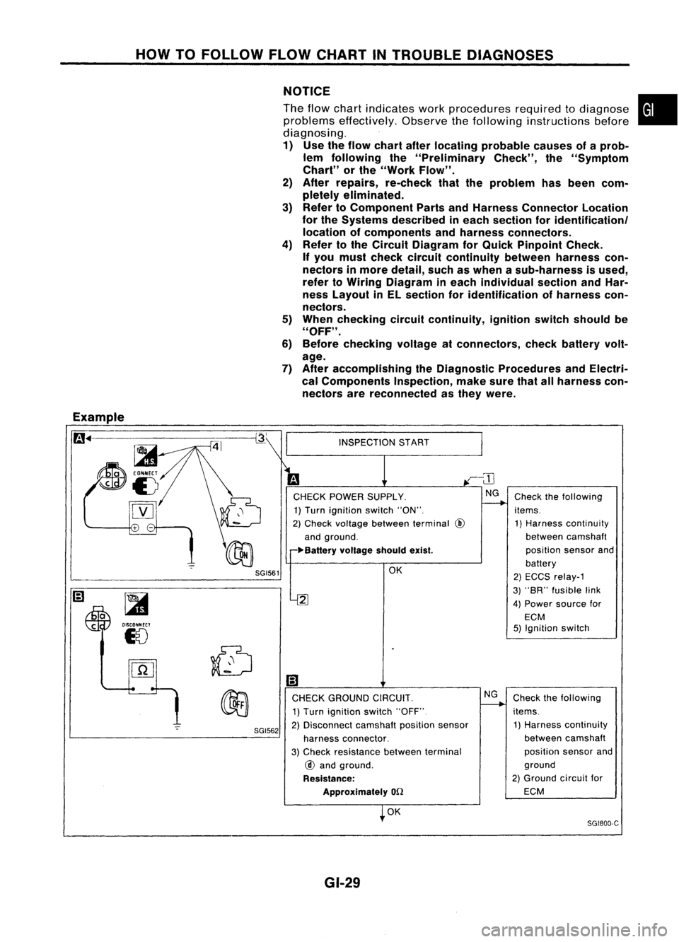
HOWTOFOLLOW FLOWCHART INTROUBLE DIAGNOSES
NOTICE
The flow chart indicates workprocedures requiredtodiagnose
problems effectively. Observethefollowing instructions before
diagnosing.
1) Use theflow chart afterlocating probable causesofaprob-
lem following the"Preliminary Check",the"Symptom
Chart" orthe "Work Flow".
2) After repairs, re-check thattheproblem hasbeen com-
pletely eliminated.
3) Refer toComponent PartsandHarness Connector Location
for the Systems described ineach section foridentificationl
location ofcomponents andharness connectors.
4) Refer tothe Circuit Diagram forQuick Pinpoint Check.
If you must check circuit continuity betweenharnesscon-
nectors inmore detail, suchaswhen asub-harness isused,
refer toWiring Diagram ineach individual sectionandHar-
ness Layout inEL section foridentification ofharness con-
nectors.
5) When checking circuitcontinuity, ignitionswitchshould be
"OFF" .
6) Before checking voltageatconnectors, checkbattery volt-
age.
7) After accomplishing theDiagnostic Procedures andElectri-
cal Components Inspection,makesurethatallharness con-
nectors arereconnected asthey were.
•
Example
m ..
-=-=~-----------~
~
~i5
[YJ
SGI561
~
OISCONNECT
18
SGI562
INSPECTION
START
CHECK POWER SUPPLY.
1) Turn ignition switch"ON".
2) Check voltage between terminal
@
and ground.
~Ba"ery voltageshouldexist.
OK
2
Ii)
CHECK GROUND CIRCUIT.
1) Turn ignition switch"OFF"
2) Disconnect camshaftpositionsensor
harness connector.
3) Check resistance betweenterminal
@
and ground.
Resistance: Approximately
on
OK
GI-29 NG
Check
thefollowing
items. 1) Harness continuity
between camshaft
position sensorand
battery
2) ECCS relay-1
3) "SR" fusible link
4) Power source for
ECM
5) Ignition switch
Check thefollowing
items. 1) Harness continuity
between camshaft
position sensorand
ground
2) Ground circuitfor
ECM
SG1800-C
Page 1399 of 1701
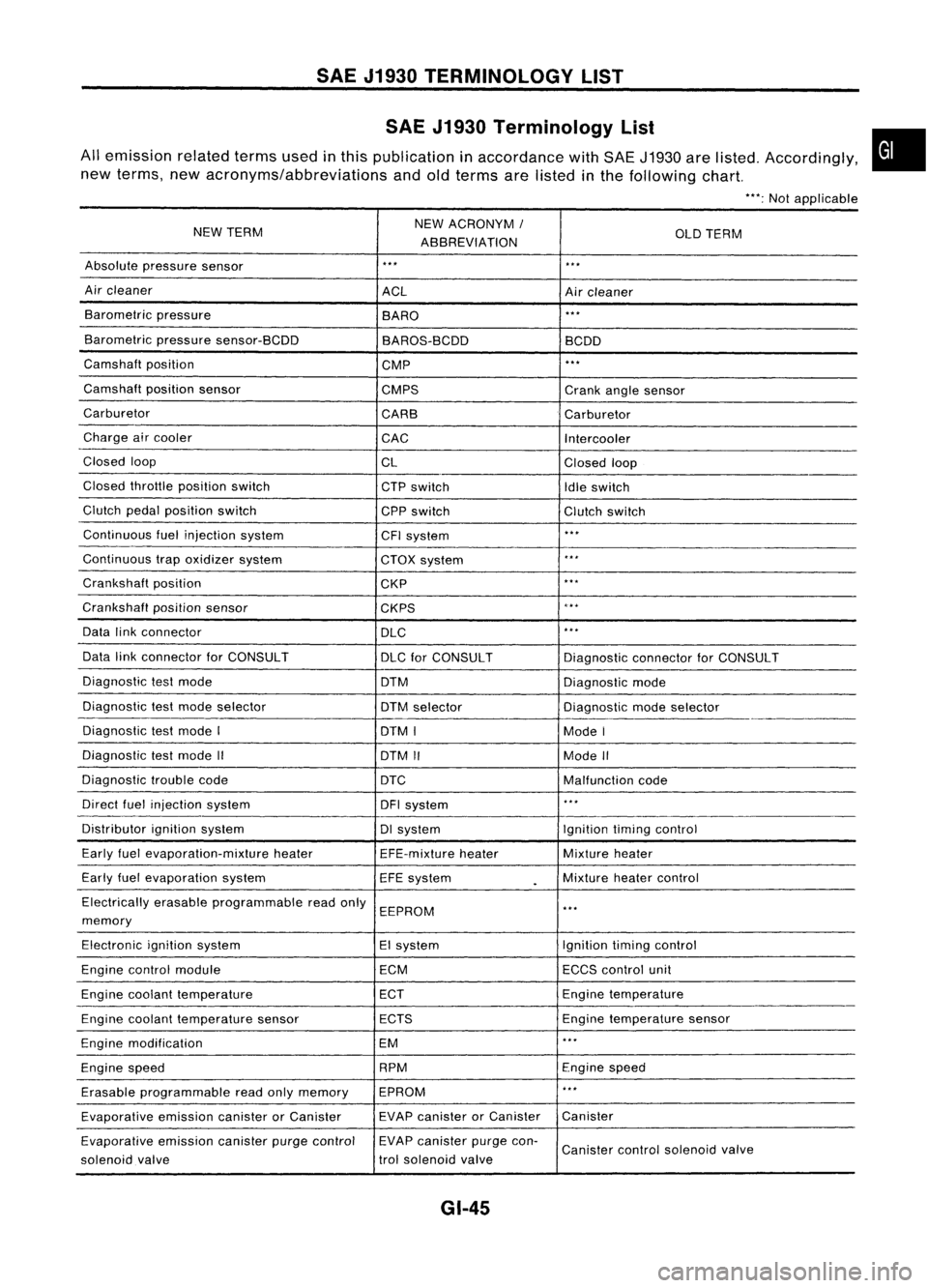
SAEJ1930 TERMINOLOGY LIST
SAE J1930 Terminology List
All emission relatedtermsusedinthis publication inaccordance withSAE J1930 arelisted. Accordingly,
new terms, newacronyms/abbreviations andoldterms arelisted inthe following chart.
"':Not applicable
NEW TERM NEW
ACRONYM /
ABBREVIATION OLD
TERM
Absolute pressure sensor
'" '"
Air cleaner
ACLAircleaner
Barometric pressure
BARO
."
Barometric pressuresensor-BCDD
BAROS-BCDD BCDD
Camshaft position
CMP
'"
Camshaft positionsensor
CMPS Crankanglesensor
Carburetor CARBCarburetor
Charge aircooler
CACIntercooler
Closed loop
CLClosedloop
Closed throttle position switch
CTPswitch
Idleswitch
Clutch pedalposition switch
CPPswitch Clutchswitch
Continuous fuelinjection system
CFIsystem
'"
Continuous trapoxidizer system
CTOXsystem
...
Crankshaft position
CKP
'"
Crankshaft positionsensor
CKPS
~.**
Data linkconnector
DLC
,
..
Data linkconnector forCONSULT
DLCforCONSULT DiagnosticconnectorforCONSULT
Diagnostic testmode
DTMDiagnosticmode
Diagnostic testmode selector
DTMselector Diagnosticmodeselector
Diagnostic testmode I
DTMI ModeI
Diagnostic testmode II
DTMII ModeII
Diagnostic troublecode
DTC Malfunctioncode
Direct fuelinjection system
DFIsystem
..
,
Distributor ignitionsystem DIsystem Ignitiontimingcontrol
Early fuelevaporation-mixture heater
EFE-mixtureheater Mixture
heater
Early fuelevaporation system
EFEsystem
.
Mixture
heatercontrol
Electrically erasableprogrammable readonly
EEPROM
'"
memory
Electronic ignitionsystem EIsystem Ignitiontimingcontrol
Engine control module ECMECCScontrol unit
Engine coolant temperature ECTEngine
temperature
Engine coolant temperature sensor ECTS Engine
temperature sensor
Engine modification EM
'"
Engine speed RPM
Enginespeed
Erasable programmable readonlymemory EPROM
'"
Evaporative emissioncanisterorCanister EVAP
canister orCanister Canister
Evaporative emissioncanisterpurgecontrol EVAP
canister purgecon-
Canister controlsolenoid valve
solenoid valve trol
solenoid valve
GI-45
•
Page 1400 of 1701
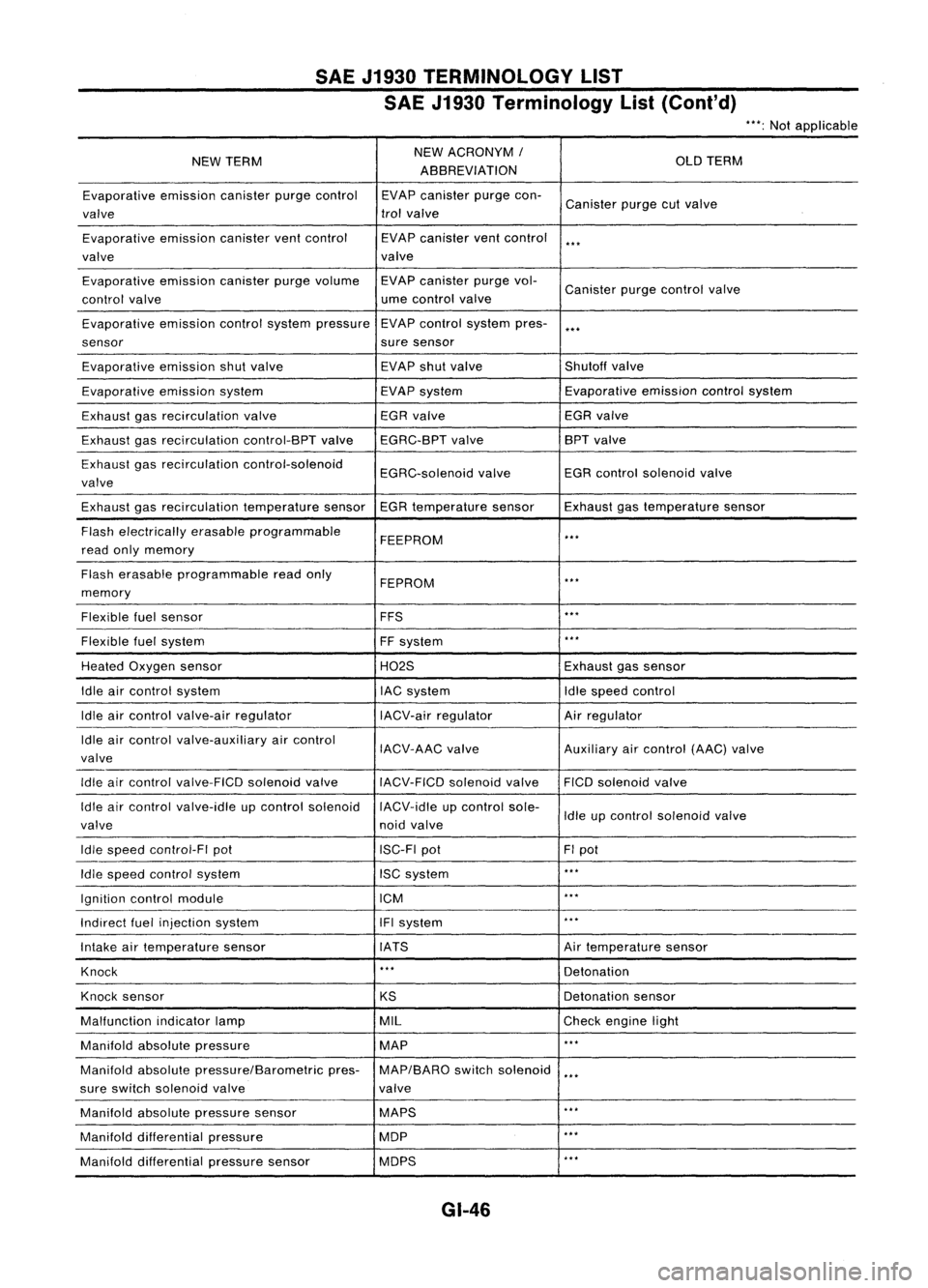
SAEJ1930 TERMINOLOGY LIST
SAE J1930 Terminology List(Cont'd)
***:
Not applicable
NEW TERM NEW
ACRONYM /
OLDTERM
ABBREVIATION
Evaporative emissioncanisterpurgecontrol EVAPcanister purgecon-
Canister purgecutvalve
valve trol
valve
Evaporative emissioncanisterventcontrol EVAPcanister ventcontrol
***
valve valve
Evaporative emissioncanisterpurgevolume EVAPcanister purgevol-
Canister purgecontrol valve
control valve ume
control valve
Evaporative emissioncontrolsystem pressure EVAP
control system pres-
***
sensor suresensor
Evaporative emissionshutvalve EVAP
shutvalve Shutoffvalve
Evaporative emissionsystem EVAPsystem Evaporative
emissioncontrolsystem
Exhaust gasrecirculation valve EGR
valve EGRvalve
Exhaust gasrecirculation control-BPTvalveEGRC-BPT valve BPT
valve
Exhaust gasrecirculation control-solenoid
EGRC-solenoidvalveEGR
control solenoid valve
valve
Exhaust gasrecirculation temperaturesensorEGRtemperature sensorExhaustgastemperature sensor
Flash electrically erasableprogrammable
FEEPROM
***
read onlymemory
Flash erasable programmable readonly
FEPROM
**.
memory
Flexible fuelsensor FFS
***
Flexible fuelsystem
FFsystem
***
Heated Oxygen sensor H02SExhaustgassensor
Idle aircontrol system lACsystem Idlespeed control
Idle aircontrol valve-air regulator IACV-airregulator Airregulator
Idle aircontrol valve-auxiliary aircontrol
IACV-AACvalve Auxiliaryaircontrol (AAC)valve
valve
Idle aircontrol valve-FICO solenoidvalve
IACV-FICDsolenoidvalve FICOsolenoid valve
Idle aircontrol valve-idle upcontrol solenoid IACV-idleupcontrol sole-
Idleupcontrol solenoid valve
valve noidvalve
Idle speed control-FI pot ISC-FIpot FIpot
Idle speed control system ISCsystem
***
Ignition controlmodule ICM
***
Indirect fuelinjection system IFIsystem
***
Intake airtemperature sensor IATS Airtemperature sensor
Knock
***
Detonation
Knock sensor
KSDetonation
sensor
Malfunction indicatorlamp MIL
Checkengine light
Manifold absolutepressure MAP
***
Manifold absolutepressure/Barometric pres-MAP/BARO switchsolenoid
***
sure switch solenoid valve valve
Manifold absolutepressure sensor MAPS
**.
Manifold differential pressure MOP
***
Manifold differential pressuresensor MOPS
***
GI-46
Page 1401 of 1701
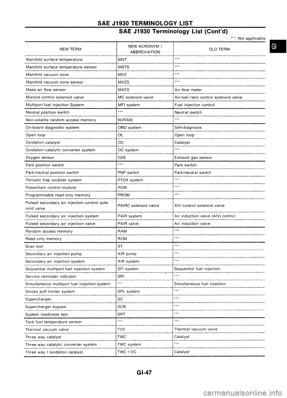
SAEJ1930 TERMINOLOGY LIST
SAE J1930 Terminology List(Cont'd)
NEW TERM NEW
ACRONYM /
OLDTERM
ABBREVIATION
Manifold surfacetemperature MST
...
Manifold surfacetemperature sensor MSTS
...
Manifold vacuumzone MVZ
...
Manifold vacuumzonesensor MVZS
...
Mass airflow sensor
MAFSAirflow meter
Mixture controlsolenoid valve
MCsolenoid valve Air-fuelratiocontrol solenoid valve
Multipart fuelinjection System MFIsystem Fuelinjection control
Neutral position switch
...
Neutralswitch
Non-volatile randomaccessmemory
NVRAM
...
On-board diagnostic system OBOsystem Self-diagnosis
Open loop
OLOpen
loop
Oxidation catalyst
OCCatalyst
Oxidation catalyticconverter system OCsystem
...
Oxygen sensor
02SExhaust
gassensor
Park position switch
...
Parkswitch
Park/neutral positionswitch
PNPswitch Park/neutralswitch
Periodic trapoxidizer system
PTOXsystem
...
Powertrain controlmodule PCM
...
Programmable readonlymemory PROM
...
Pulsed secondary airinjection controlsole-
PAIRCsolenoid valve AIV
control solenoid valve
noid valve
Pulsed secondary airinjection system PAIRsystem Air
induction valve(AIV)control
Pulsed secondary airinjection valve PAIR
valve Airinduction valve
Random accessmemory RAM
...
Read onlymemory ROM
...
Scan tool ST
...
Secondary airinjection pump AIRpump
...
Secondary airinjection system AIR
system
...
Sequential multiportfuelinjection system SFI
system Sequentialfuelinjection
.
Service reminder indicator SRI
...
Simultaneous multipartfuelinjection system
...
Simultaneousfuelinjection
Smoke pufflimiter system SPL
system
...
Supercharger SC
...
Supercharger bypass 5CB
...
System readiness test 5RT
...
Tank fueltemperature sensor
...
...
Thermal vacuumvalve TVV
Thermal
vacuumvalve
Three waycatalyst TWC
Catalyst
Three waycatalytic converter system TWC
system
...
Three way+oxidation catalyst TWC+OC Catalyst
GI-47
Page 1402 of 1701
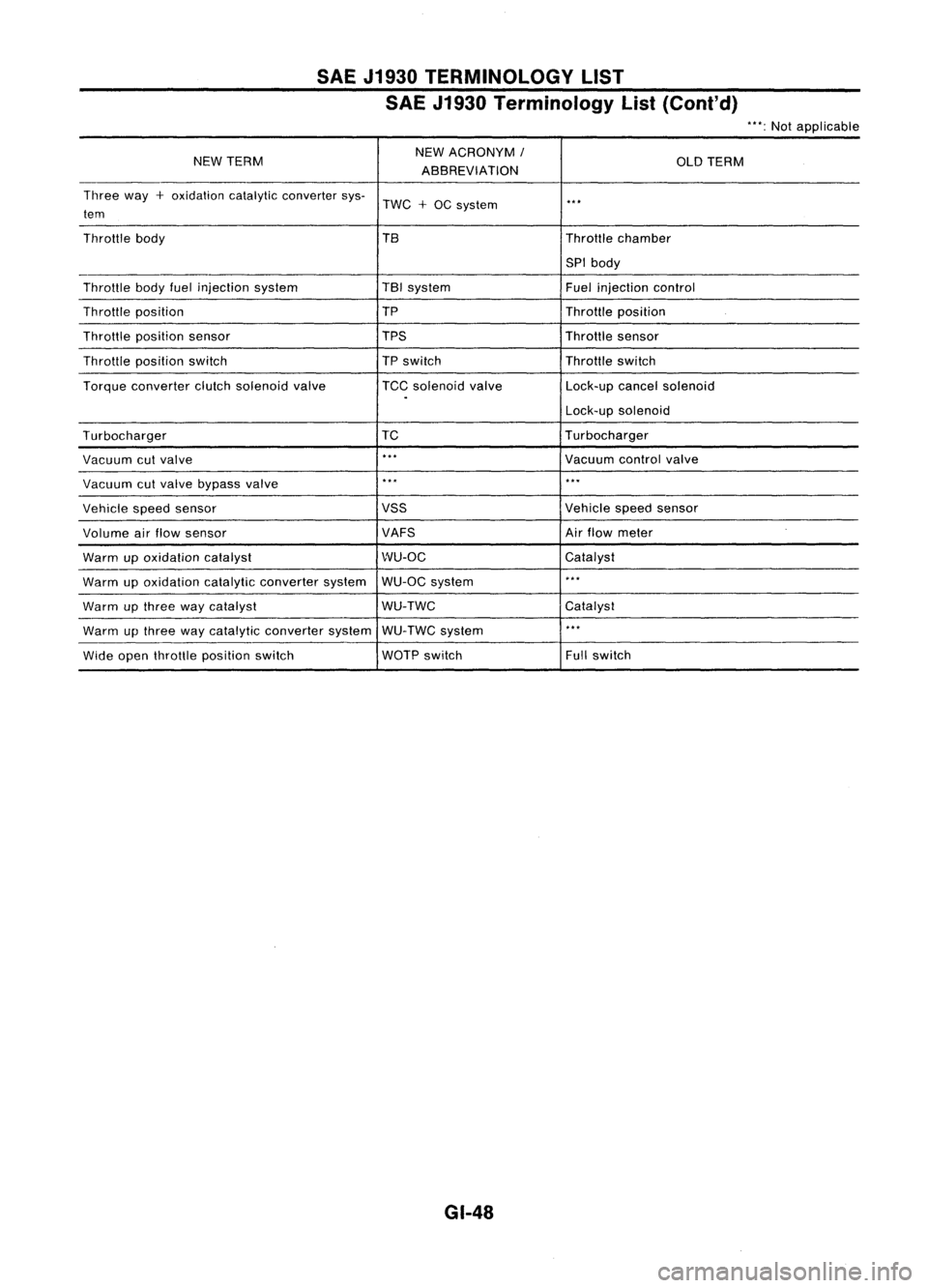
SAEJ1930 TERMINOLOGY LIST
SAE J1930 Terminology List(Cont'd)
"':Not applicable
NEW TERM NEW
ACRONYM
I
OLDTERM
ABBREVIATION
Three way
+
oxidation catalyticconverter sys-
TWC
+
OC system
..
,
tem
Throttle body TBThrottlechamber
SPI body
Throttle bodyfuelinjection system TBI
system
Fuelinjection control
Throttle position TP
Throttleposition
Throttle position sensor TPSThrottlesensor
Throttle position switch
TP
switch Throttleswitch
Torque converter clutchsolenoid valve TCCsolenoid valve Lock-upcancelsolenoid
.
Lock-upsolenoid
Turbocharger TC
Turbocharger
Vacuum cutvalve
..
,
Vacuumcontrolvalve
Vacuum cutvalve bypass valve
..
,
...
Vehicle speedsensor VSS
Vehiclespeedsensor
Volume airflow sensor VAFSAir
flow meter
Warm upoxidation catalyst WU-OC
Catalyst
Warm upoxidation catalyticconverter systemWU-OC
system
..
,
Warm upthree waycatalyst WU-TWC
Catalyst
Warm upthree waycatalytic converter systemWU-TWC system
..
,
Wide open throttle position switch WOTP
switch Fullswitch
GI-48
Page 1404 of 1701
PRECAUTIONSANDPREPARATION
Supplemental RestraintSystem(SRS)"AIR
BAG" (DualAirBag System)
The Supplemental RestraintSystem"AirBag" usedalong withaseat belt,helps toreduce therisk or
severity ofinjury tothe driver andfront passenger inafrontal collision. TheSupplemental Restraint
System consists ofair bag modules (locatedinthe center ofthe steering wheelandonthe instrument
panel onthe passenger side),adiagnosis sensorunit,warning lamp,wiring harness andspiral cable.
Information necessarytoservice thesystem safelyisincluded inthe
RSsection
ofthis Service Manual.
WARNING:
• Toavoid rendering theSRS inoperative, whichcouldincrease therisk ofpersonal injuryordeath
in the event ofacollision whichwould resultinair bag inflation, allmaintenance mustbeperformed
by an authorized NISSANdealer.
• Improper maintenance, includingincorrectremovalandinstallation ofthe SRS, canlead topersonal
injury caused byunintentional activationofthe system.
• Donot use electrical testequipment onany circuit related tothe SRS unless instructed tointhis
Service Manual. SRSwiring harnesses arecovered withyellow insulation eitherjustbefore the
harness connectors orfor the complete harness,foreasy identification.
Supplemental RestraintSystem(SRS)"AIR
BAG" (Single AirBag System)
The Supplemental RestraintSystem"AirBag" andused along withaseat belt,helps toreduce therisk
or severity ofinjury tothe driver inafrontal collision. TheSupplemental RestraintSystemconsists of
an air bag module (located inthe center ofthe steering wheel),adiagnosis sensorunit,warning lamp,
wiring harness andspiral cable. Information necessarytoservice thesystem safelyisincluded inthe
RS section
ofthis Service Manual.
WARNING: • Toavoid rendering theSRS inoperative, whichcouldincrease therisk ofpersonal injuryordeath
in the event ofacollision whichwould resultinair bag inflation, allmaintenance mustbeperformed
by anauthorized NISSANdealer.
• Improper maintenance, includingincorrectremovalandinstallation ofthe SRS, canlead topersonal
injury caused byunintentional activationofthe system.
• Donot use electrical testequipment onany circuit related tothe SRS unless instructed tointhis
Service Manual.
HA-2
Page 1487 of 1701
SECTION
CONTENTS
MAINTENANCE
MA
•
PRECAUTIONS ANDPREPARATION
3
Supplemental RestraintSystem(SRS)"AIR
BAG" (DualAirBag System) 3
Supplemental RestraintSystem(SRS)"AIR
BAG" (Single AirBag System) 3
Special Service Tools 4
Commercial ServiceTool 4
PRE-DELIVERY INSPECTIONITEMS
5
GENERAL MAINTENANCE 6
PERIODIC MAINTENANCE (Exceptfor
Europe) 7
Engine andEmission ControlService 7
Chassis andBody Service 8
Maintenance UnderSevere DrivingConditions 9
PERIODIC MAINTENANCE (ForEurope) 10
Engine Oil
&
Minor Service 10
Engine andEmission ControlService 11
Chassis andBody Services 12
Maintenance UnderSevere Driving Conditions 13
RECOMMENDED LUBRICANTSANDFLUIDS 14
Lubricants andFluids 14
SAE Viscosity Number 15
Anti-freeze CoolantMixtureRatio 16
~ --ll
GA
I I
ENGINE MAINTENANCE 17
Checking DriveBelts 17
Changing EngineCoolant... 19
Checking CoolingSystem 21
Checking FuelLines 22
Changing FuelFilter 22
Cleaning andChanging AirCleaner Filter 23
Changing EngineOil 24
Changing OilFilter 24
Checking andChanging SparkPlugs 25
Checking IgnitionWires 26Changing
PositiveCrankcase Ventilation
(PCV) Filter 26
Checking EVAPVapor Lines 26
Checking OxygenSensor(02S)orHeated
Oxygen Sensor(H02S) 27
~ --ll
SR
I I
ENGINE MAINTENANCE 28
Checking DriveBelts 28
Changing EngineCoolant... 29
Checking CoolingSystem 31
Checking FuelLines 32
Changing FuelFilter 32
Changing AirCleaner Filter 33
Changing EngineOil 33
Changing OilFilter 34
Changing SparkPlugs(Platinum-tipped type)34
Checking IgnitionWires 35
Checking EVAPVapor
&
Purge Lines 36
Checking HeatedOxygen Sensor(H02S) 37
~_~ ..-JI
CD
I I
ENGINE MAINTENANCE
38
Manifold NutCheck 38
Checking DriveBelt 38
Changing EngineCoolant. 38
Checking CoolingSystem .40
Checking FuelLine .40
Changing AirCleaner Filter 41
Water Draining, FuelFilter Check and
Replacement 41
Changing EngineOil .41
Changing EngineOilFilter 42
Checking InjectionNozzle 43
Checking IdleSpeed .44
Replacing TimingBelt 44