sensor NISSAN ALMERA N15 1995 Service Manual
[x] Cancel search | Manufacturer: NISSAN, Model Year: 1995, Model line: ALMERA N15, Model: NISSAN ALMERA N15 1995Pages: 1701, PDF Size: 82.27 MB
Page 1489 of 1701
PRECAUTIONSANDPREPARATION
Supplemental RestraintSystem(SRS)"AIR
BAG" (DualAirBag System)
The Supplemental RestraintSystem"AirBag", usedalong withaseat belt,helps toreduce therisk or•
severity ofinjury tothe driver andfront passenger inafrontal collision. TheSupplemental Restraint
i
System consists ofair bag modules (locatedinthe center ofthe steering wheelandonthe instrument
panel onthe passenger side).adiagnosis sensorunit,warning lamp,wiring harness andspiral cable.
Information necessarytoservice thesystem safelyisincluded inthe
RSsection
ofthis Service Manual.
WARNING:
• Toavoid rendering theSRS inoperative, whichcouldincrease therisk ofpersonal injuryordeath
in the event ofacollision whichwould resultinair bag inflation, allmaintenance mustbeperformed
by an authorized NISSANdealer.
• Improper maintenance, includingincorrectremovalandinstallation ofthe SRS, canlead topersonal
injury caused byunintentional activationofthe system.
• Donot use electrical testequipment onany circuit related tothe SRS unless instructed tointhis
Service Manual. SRSwiring harnesses arecovered withyellow insulation eitherjustbefore the
harness connectors orfor the complete harness,foreasy identification.
Supplemental RestraintSystem(SRS)"AIR
BAG" (Single AirBag System)
The Supplemental RestraintSystem"AirBag", usedalong withaseat belt,helps toreduce therisk or
severity ofinjury tothe driver inafrontal collision. TheSupplemental RestraintSystemconsists ofan
air bag module (located inthe center ofthe steering wheel),adiagnosis sensorunit,warning lamp,
wiring harness andspiral cable. Information necessarytoservice thesystem safelyisincluded inthe
RS section
ofthis Service Manual.
WARNING:
• Toavoid rendering theSRS inoperative, whichcouldincrease therisk ofpersonal injuryordeath
in the event ofacollision whichwould resultinair bag inflation, allmaintenance mustbeperformed
by an authorized NISSANdealer.
• Improper maintenance, includingincorrectremovalandinstallation ofthe SRS, canlead topersonal
injury caused byunintentional activationofthe system.
• Donot use electrical testequipment onany circuit related tothe SRS.
MA-3
Page 1493 of 1701

PERIODICMAINTENANCE (ExceptforEurope)
The following tablesshowthenormal maintenance schedule.Depending uponweather andatmospheric
conditions, varyingroadsurfaces, individual drivinghabitsandvehicle usage,additional ormore fre-
quent maintenance mayberequired.
Periodic maintenance beyondthelast period shown onthe tables requires similarmaintenance .
Engine andEmission ControlService
•
Abbreviations: I
=
Inspect andcorrect orreplace asnecessary. R
MAINTENANCE OPERATION
Perform eitheratnumber ofkilometers (miles)
or months, whichever comestirst. km
x1,000
(Miles x1,000)
Months
Replace.
A
=
Adjust, C
=
Clean.
MAINTENANCE INTERVAL
10 20 3040
506070
80
Reference page
(6) (12) (18)
(24)(30)(36)(42)(48)
6 12 18
24
3036
42 48
Underhood andunder vehicle GA
SR
Intake
&
exhaust valveclearance (GA15DE
&
GA16DE engines) SeeNOTE (1)
EM41
-
Drive belts
II
MA 17
24
Engine anti-Ireeze coolant(Ethylene glycolbase)(LLC) RRMA 1929
Engine coolant (Softwater) RRR
R
R R
R
RMA
1929
Cooling system
I
I
I
I
MA 2131
Fuel lines
I
I
MA
22
32
Air cleaner filter(Drypaper type)*
CC
C RC CC RMA 23
-
Air cleaner filter(Viscous papertype)* R
RMA
2333
Engine oil(Use APISE,SF.SGorSH oil)*
R
RRRR R
RR
MA 24
33
Engine oilfilter* R
R R
R
R RRRMA
2433
Fuel filter* R
RMA
22
32
Spark plugs(except Platinum-tipped type) R
RMA
25
-
Spark plugs(platinum-tipped type) Replaceevery100,000 km(60.000 miles). MA
-
34
Ignition wires
I
I
MA
2635
PCV filter* R
RMA
26
-
Vapor lines
I
I
MA
26
36
(Heated) OxygenSensor
I
I
MA 2737
NOTE: (1)
If
valve noiseincreases, checkvalveclearance.
*
Maintenance itemswith
"*"
should beperformed morefrequently accordingto"Maintenance undersevere driv-
ing conditions".
MA-7
Page 1497 of 1701
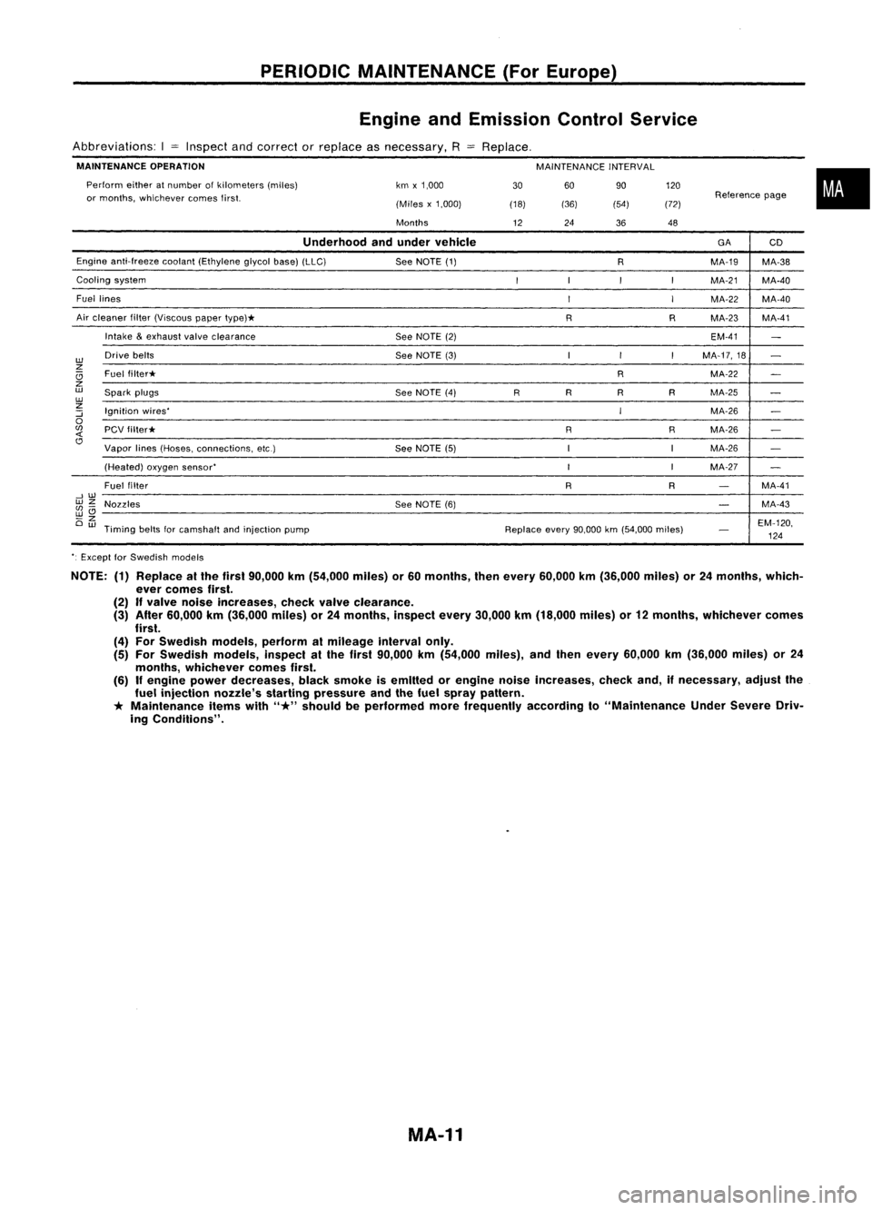
PERIODICMAINTENANCE (ForEurope)
Engine andEmission ControlService
Abbreviations: I
=
Inspect andcorrect orreplace asnecessary,
R
MAINTENANCE OPERATION
MAINTENANCEINTERVAL
60 90
(36) (54)
Perform
eitheratnumber ofkilometers (miles)
or months, whichever comesfirst. km
x1,000
(Miles x1,000)
Months
Replace,
30
(18)
12 24
36120
(72) 48
Reference
page
•
Underhood andunder vehicle
GA
CD
Engine anti-freeze cootant(Ethylene glycolbase)(LLC)
SeeNOTE (1)
RMA-19
MA-38
Cooling system
I
I
I
I
MA-21 MA-40
Fuel lines
I
I
MA-22
MA-40
Air cleaner filter(Viscous papertype)*
RRMA-23 MA-41
Intake
&
exhaust valveclearance
SeeNOTE (2) EM-41
-
w
Drive
belts
SeeNOTE (3) I
I
I
MA-17,18
-
z
Ci
Fuel
filter* RMA-22
-
z
w
Spark plugs
SeeNOTE (4)
RR
RRMA-25
-
w
z
Ignition wires'
IMA-26
:::;
-
0
(fJ
PCVfilter* RRMA-26
-
<{
Cl
Vapor lines(Hoses, connections, etc.)
SeeNOTE (5) IIMA-26
-
(Heated) oxygensensor'
I
IMA-27
-
Fuel filter
RR
-
MA-41
--,w
wz
Nozzles SeeNOTE (6)
-
MA-43
(fJ-
wCl
-z
EM-120,
Ow
Timing beltsforcamshalt andinjection pump Replaceevery90,000 km(54,000 miles)
-
124
'. Except forSwedish models
NOTE: (1)Replace atthe first 90,000 km(54,000 miles)or60 months, thenevery 60,000 km(36,000 miles)or24 months, which-
ever comes first.
(2)
If
valve noise Increases, checkvalveclearance.
(3) After 60,000 km(36,000 miles)or24 months, inspectevery30,000 km(18,000 miles)or12 months, whichever comes
first.
(4) For Swedish models,performalmileage intervalonly.
(5) For Swedish models,inspectalthe first 90,000 km(54,000 miles),andthen every 60,000 km(36,000 miles)or24
months, whichever comesfirst.
(6)
If
engine powerdecreases, blacksmoke isemitted orengine noiseincreases, checkand,ifnecessary, adjustthe
fuel injection nozzle'sstartingpressure andthefuel spray pattern.
*
Maintenance itemswith
"*"
should beperformed morefrequently accordingto"Maintenance UnderSevere Driv-
ing Conditions".
MA-11
Page 1513 of 1701
ENGINEMAINTENANCE
SEF051PA SEF909P
*
NO FAIL
0
~y~r
GrJ-~
Data linkconnector forCONSULT
(Connect CHKandIGN terminals
with asuitable harness.)
•
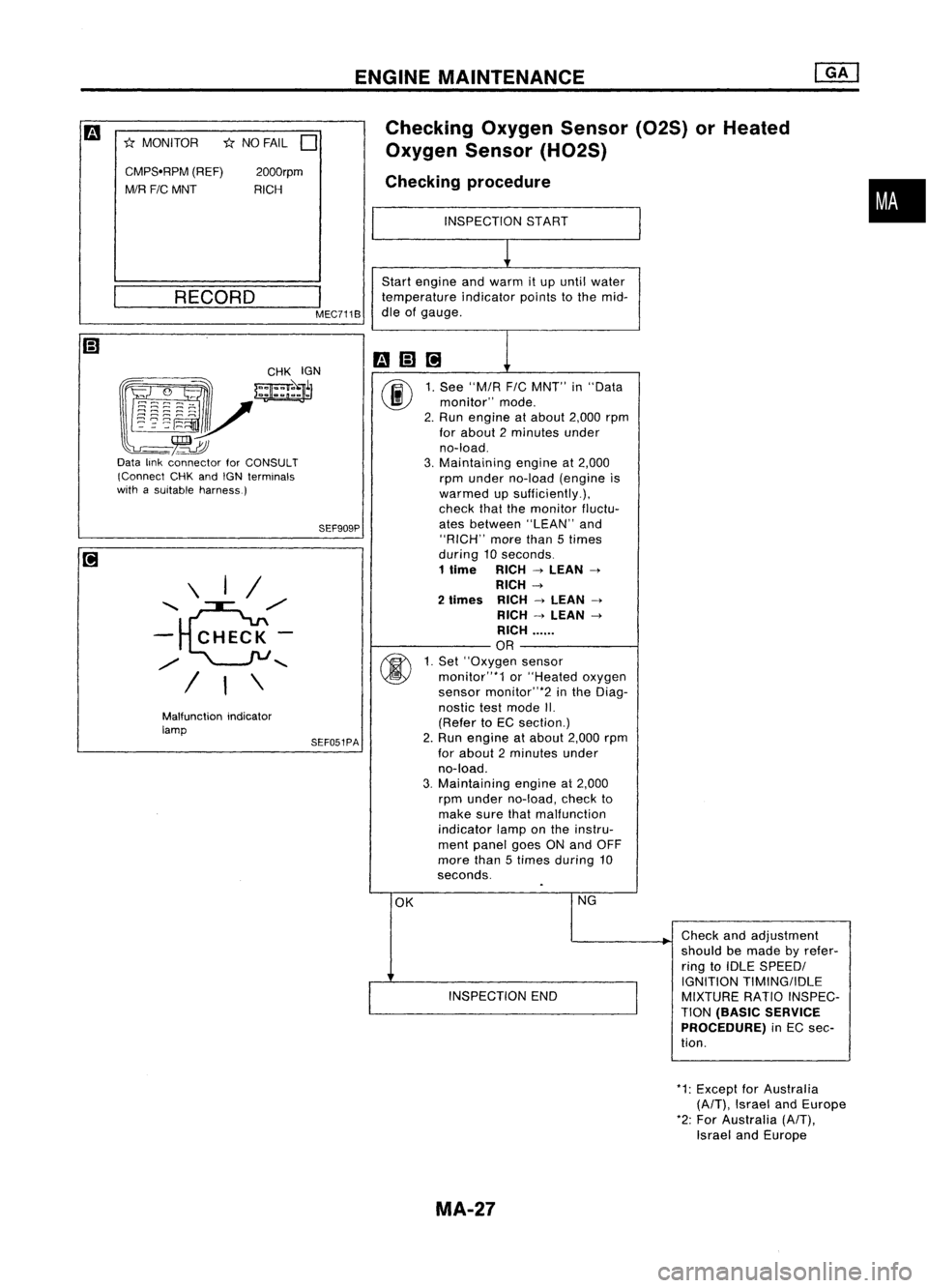
Checking
OxygenSensor(02S)orHeated
Oxygen Sensor(H02S)
Checking procedure
INSPECTION START
~
Start engine andwarm itup until water
temperature indicatorpointstothe mid-
dle ofgauge.
mm@]
1
00
1.
See "MIA
FIC
MNT" in"Data
monitor" mode.
2. Run engine atabout 2,000rpm
for about 2minutes under
no-load.
3. Maintaining engineat2,000
rpm under no-load (engine is
warmed upsufficiently.),
check thatthemonitor fluctu-
ates between "LEAN"and
"RICH" morethan5times
during 10seconds.
1
lime
RICH
->
LEAN
->
RICH
->
2
limes
RICH
->
LEAN
->
RICH
->
LEAN
->
RICH ......
OR
00
1.
Set' 'Oxygen sensor
monitor"*1 or"Heated oxygen
sensor monitor"*2 inthe Diag-
nostic testmode II.
(Refer toEC section.)
2. Run engine atabout 2,000rpm
for about 2minutes under
no-load.
3. Maintaining engineat2,000
rpm under no-load, checkto
make surethatmalfunction
indicator lamponthe instru-
ment panel goesONand OFF
more than5times during 10
seconds.
OK NG
Checkandadjustment
should bemade byrefer-
ring toIDLE SPEEDI
I
IGNITION
TIMINGIIDLE
INSPECTION END
MIXTURERATIOINSPEC-
TION
(BASIC SERVICE
PROCEDURE)
inEC sec-
tion.
I
MEC711B
2000rpm
RICH
RECORD
Malfunction indicator
lamp \
I/
'e/'
-
CHECK-
/
"
/ I\
CMPS'RPM
(REF)
MIR FIC
MNT
*
MONITOR
*1:Except forAustralia
(A/T),
Israel andEurope
*2: For Australia
(A/T),
Israel andEurope
MA-27
Page 1523 of 1701
ENGINEMAINTENANCE
SEF051PA SEF909P
*
NO FAIL
D
Malfunction indicator
lamp
•
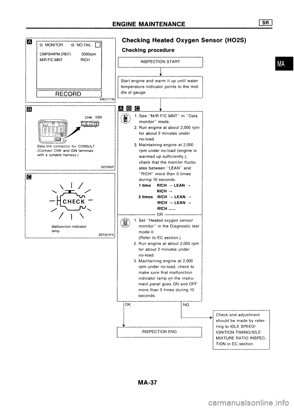
Checking
HeatedOxygen Sensor(H02S)
Checking procedure
INSPECTION START
1
Start engine andwarm itup until water
temperature indicatorpointstothe mid-
dle ofgauge.
m(;]ri
1
00
1.
See "M/R F/CMNT" in"Data
monitor" mode.
2. Run engine atabout 2,000rpm
for about 2minutes under
no-load.
3. Maintaining engineat2,000
rpm under no-load (engine is
warmed upsufficiently.),
check thatthemonitor fluctu-
ates between "LEAN"and
"RICH" morethan5times
during 10seconds.
1 time RICH
-4
LEAN
-4
RICH
-4
2
times RICH
-4
LEAN
-4
RICH
-4
LEAN
-4
RICH ......
OR
@
1.
Set "Heated oxygensensor
monitor" inthe Diagnostic test
mode II.
(Refer toEC section)
2. Run engine atabout 2,000rpm
for about 2minutes under
no-load.
3. Maintaining
engineat2,000
rpm under no-load, checkto
make surethatmalfunction
indicator lamp~nthe instru-
ment panel goesONand OFF
more than5times during 10
seconds.
OK NG
.
Check
andadjustment
should bemade byrefer-
ring toIDLE SPEEDI
INSPECTION END
IGNITIONTIMING/IDLE
MIXTURE RATIOINSPEC-
TION inEC section
2000rpm
RICH
\ I/
........ e./
- CHECK-
./
........
/ I\
CMPS.RPM
(REF)
M/R FICMNT
*
MONITOR
__ R_E_C_O_R_D __
I
MEC711B
~~~~:?~;~
~~r
l~~~~V
-~~
Data linkconnector forCONSULT
(Connect CHKandIGN terminals
with asuitable harness.)
MA-37
Page 1527 of 1701
ENGINEMAINTENANCE
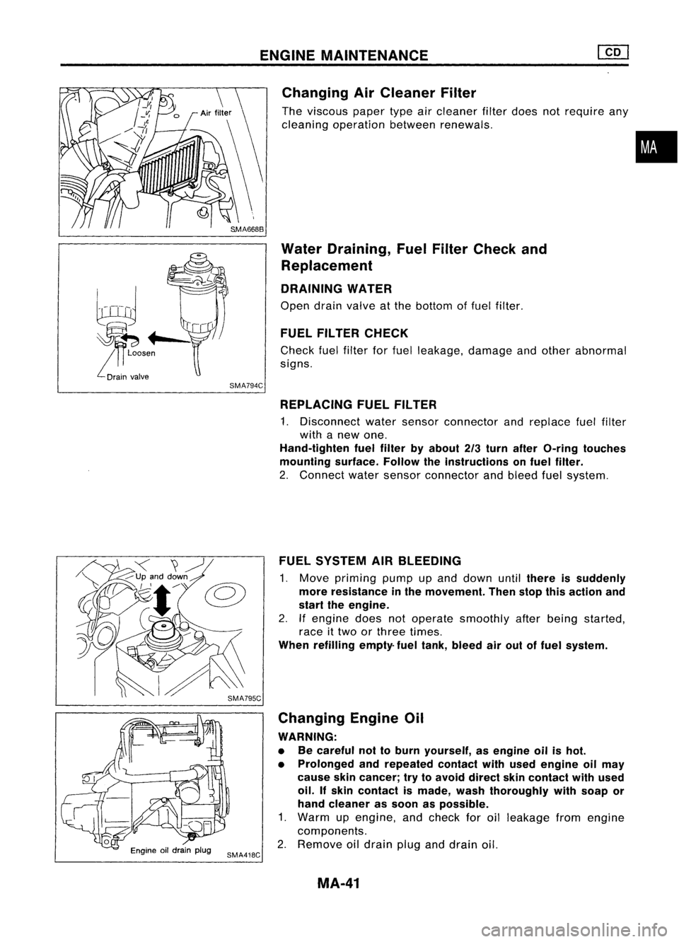
Changing AirCleaner Filter
The viscous papertypeaircleaner filterdoes notrequire any
cleaning operation betweenrenewals.
Water Draining, FuelFilter Check and
Replacement
DRAINING WATER
Open drainvalve atthe bottom offuel filter.
FUEL FILTER CHECK
Check fuelfilter forfuel leakage, damageandother abnormal
signs.
•
SMA794C REPLACING FUELFILTER
1. Disconnect watersensor connector andreplace fuelfilter
with anew one.
Hand-tighten fuelfilter byabout 2/3turn after O-ring touches
mounting surface.Followtheinstructions onfuel filter.
2. Connect watersensor connector andbleed fuelsystem.
FUEL SYSTEM AIRBLEEDING
1. Move priming pumpupand down until
there issuddenly
more resistance inthe movement. Thenstopthisaction and
start theengine.
2. Ifengine doesnotoperate smoothly afterbeing started,
race ittwo orthree times.
When refilling empty-fueltank, bleed airout offuel system.
Changing EngineOil
WARNING:
• Becareful nottoburn yourself, asengine oilishot.
• Prolonged andrepeated contactwithused engine oilmay
cause skincancer; trytoavoid direct skincontact withused
oil. Ifskin contact ismade, washthoroughly withsoap or
hand cleaner assoon aspossible.
1. Warm upengine, andcheck foroilleakage fromengine
components.
2. Remove oildrain pluganddrain oil.
MA-41
Page 1549 of 1701
REMOVALANDINSTALLATION
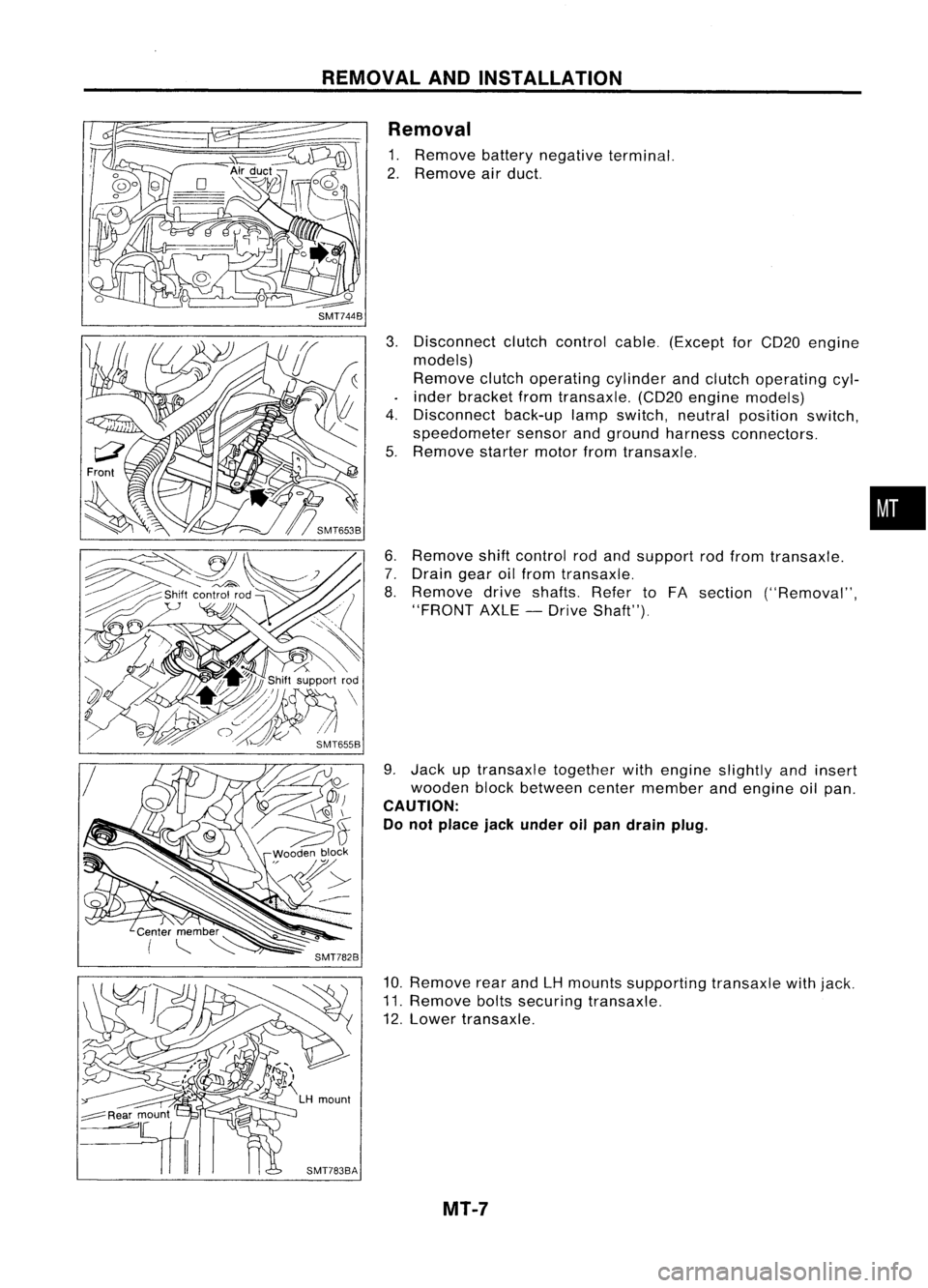
Removal
1. Remove batterynegative terminal.
2. Remove airduct.
3. Disconnect clutchcontrol cable.(Except forCD20 engine
models)
Remove clutchoperating cylinderandclutch operating cyl-
inder bracket fromtransaxle. (CD20engine models)
4. Disconnect back-uplampswitch, neutralposition switch,
speedometer sensorandground harness connectors.
5. Remove startermotorfromtransaxle.
6. Remove shiftcontrol rodand support rodfrom transaxle.
7. Drain gearoilfrom transaxle.
8. Remove driveshafts. RefertoFA section ("Removal",
"FRONT AXLE-Drive Shaft").
9. Jack uptransaxle togetherwithengine slightly andinsert
wooden blockbetween centermember andengine oilpan.
CAUTION:
Do not place jackunder oilpan drain plug.
10. Remove rearandLHmounts supporting transaxlewithjack.
11. Remove boltssecuring transaxle.
12. Lower transaxle.
MT-7
•
Page 1614 of 1701
REARAXLE
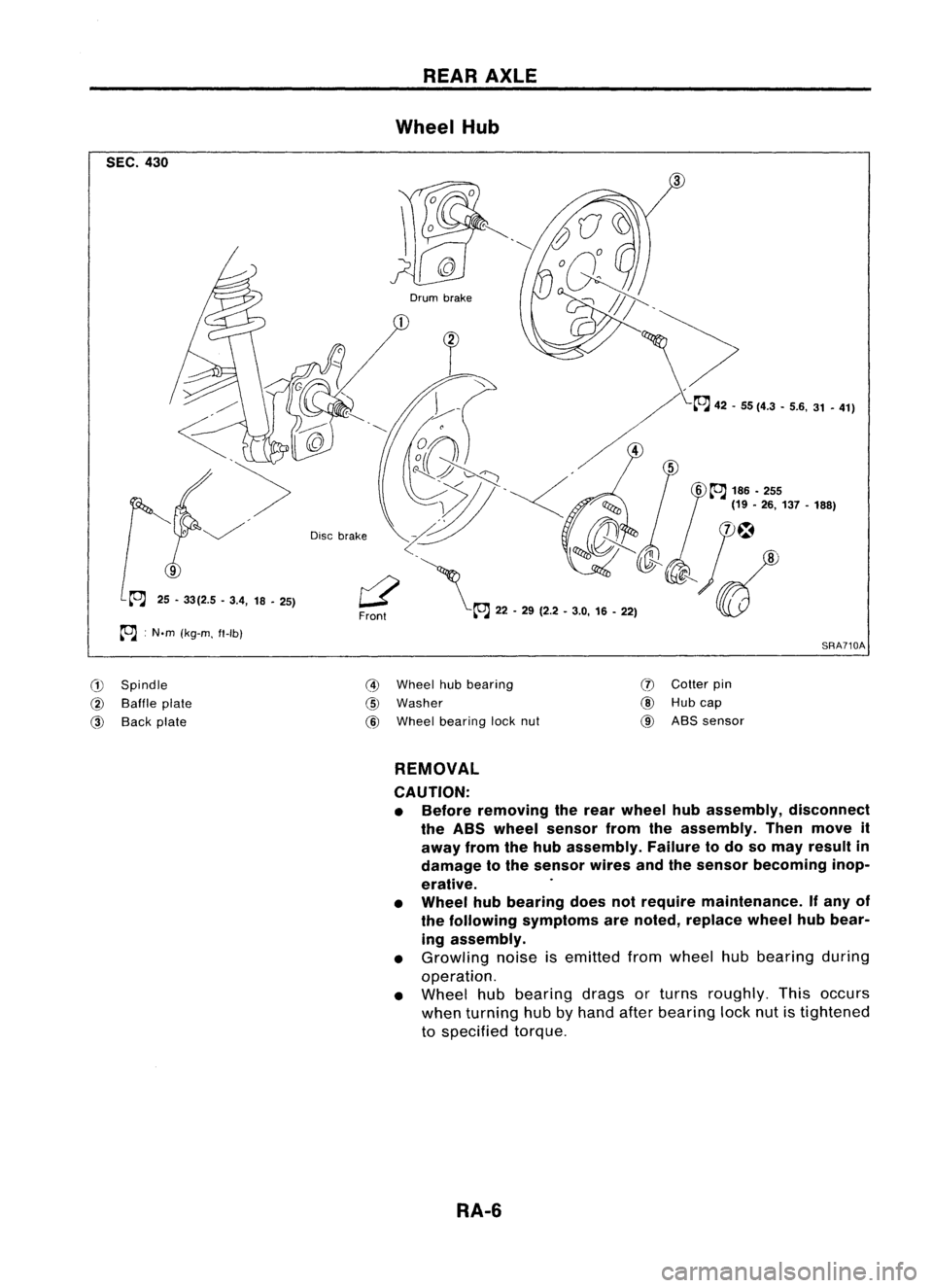
Wheel Hub
SEC. 430
SRA710A
6
~
186 •255
(19 •26, 137 -188)
Drum
brake
r2'\
Front ~22-29 (2.2 •3.0, 16-22)
Disc
brake
25 -33(2.5 -3.4, 18-25)
~ :N.m (kg-m. ft-Ib)
G)
Spindle
@
Baffle plate
@
Back plate
@
Wheel hubbearing
@
Washer
@
Wheel bearing locknut
(J)
Cotter pin
@
Hubcap
@
ABS sensor
REMOVAL
CAUTION:
• Before removing therear wheel hubassembly, disconnect
the ABS wheel sensor fromtheassembly. Thenmove it
away fromthehub assembly. Failuretodo somay result in
damage tothe sensor wiresandthesensor becoming inop-
erative.
• Wheel hubbearing doesnotrequire maintenance. Ifany of
the following symptoms arenoted, replace wheelhubbear-
ing assembly.
• Growling noiseisemitted fromwheel hubbearing during
operation.
• Wheel hubbearing dragsorturns roughly. Thisoccurs
when turning hubbyhand afterbearing locknutistightened
to specified torque.
RA-6
Page 1616 of 1701
REARSUSPENSION
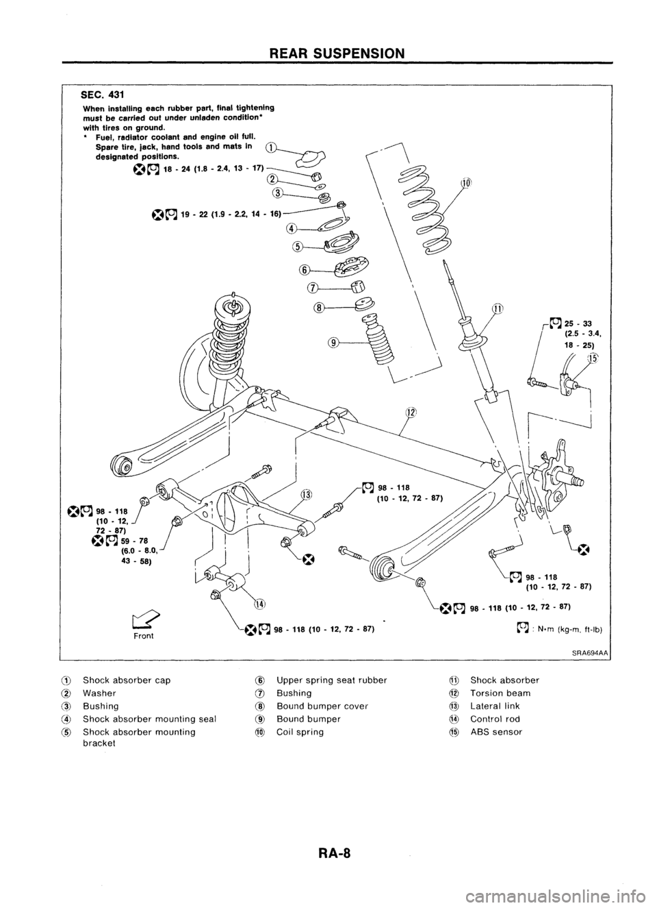
SEC. 431
~:N'm (kg-m. fl-Ib)
L'~
~;.;
~~.4,
18 •25)
~'
\ \ i---J
~~ ~
- ~98•118 (
I~ / 110-12,72-87) ~-~~~
@
~
"
\..-~
~ ~;:;:Y ~ '-~.
--...~~ ~~98-118
~ (10-12, 72•87)
~~A
98-118 (10-12, 72-87)
When
installing eachrubber part,finaltightening
must becarried outunder unladen condition"
with tires onground.
" Fuel, radiator coolantandengine allfull.
Spare tire,jack, handtools andmats In~
designated positions. ~
~~ 18.24(1.8.2.4, 13-17)~
~
~A
19•22 (1.9 -2.2, 14•16)~
~
~
~
:\\
\--/
Front
SRA694AA
(1)
Shock absorber cap
@
Washer
@
Bushing
@
Shock absorber mounting seal
@
Shock absorber mounting
bracket
@
Upper spring seatrubber
(J)
Bushing
@
Bound bumper cover
@
Bound bumper
@J
Coilspring
Q!J
Shock absorber
@
Torsion beam
@
Lateral link
Q4)
Control rod
@)
ABSsensor
RA-8
Page 1617 of 1701
SRA696A
SRA697A
S
Control rod
Lateral link
~H";""I"
ITorsion
beam
SRA698AREAR
SUSPENSION
Removal andInstallation
CAUTION:
• Before removing therear suspension assembly,disconnect
the ABS wheel sensor fromtheassembly. Failuretodo so
may result indamage tothe sensor wiresandthesensor
becoming inoperative.
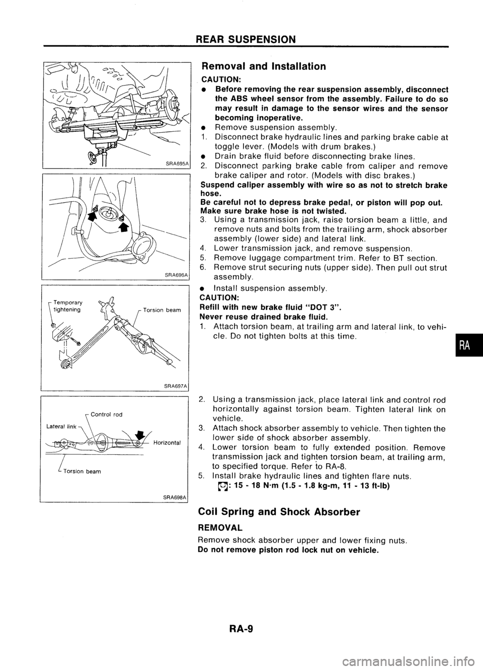
• Remove suspension assembly.
1. Disconnect brakehydraulic linesandparking brakecableat
toggle lever.(Models withdrum brakes.)
• Drain brake fluidbefore disconnecting brakelines.
2. Disconnect parkingbrakecablefromcaliper andremove
brake caliper androtor. (Models withdiscbrakes.)
Suspend caliperassembly withwire soasnot tostretch brake
hose.
Be careful nottodepress brakepedal, orpiston willpop out.
Make surebrake hoseisnot twisted.
3. Using atransmission jack,raise torsion beamalittle, and
remove nutsandbolts fromthetrailing arm,shock absorber
assembly (lowerside)andlateral link.
4. Lower transmission jack,andremove suspension.
5. Remove luggagecompartment trim.Refer toBT section.
6. Remove strutsecuring nuts(upper side).Thenpulloutstrut
assembly.
• Install suspension assembly.
CAUTION: Refill withnewbrake fluid"DOT
3".
Never reusedrained brakefluid.
1. Attach torsion beam,attrailing armandlateral link,tovehi-
cle. Donot tighten boltsatthis time.
2. Using atransmission jack,place lateral linkand control rod
horizontally againsttorsionbeam.Tighten laterallinkon
vehicle.
3. Attach shockabsorber assembly tovehicle. Thentighten the
lower sideofshock absorber assembly.
4. Lower torsion beamtofully extended position.Remove
transmission jackandtighten torsion beam,attrailing arm,
to specified torque.RefertoRA-8.
5. Install brakehydraulic linesandtighten flarenuts.
~: 15-18 N'm (1.5.1.8 kg-m,11-13 ft-Ib)
Coil Spring andShock Absorber
REMOVAL
Remove shockabsorber upperandlower fixing nuts.
Do not remove pistonrodlock nutonvehicle.
RA-9
•