relay NISSAN ALMERA N15 1995 Owner's Manual
[x] Cancel search | Manufacturer: NISSAN, Model Year: 1995, Model line: ALMERA N15, Model: NISSAN ALMERA N15 1995Pages: 1701, PDF Size: 82.27 MB
Page 348 of 1701
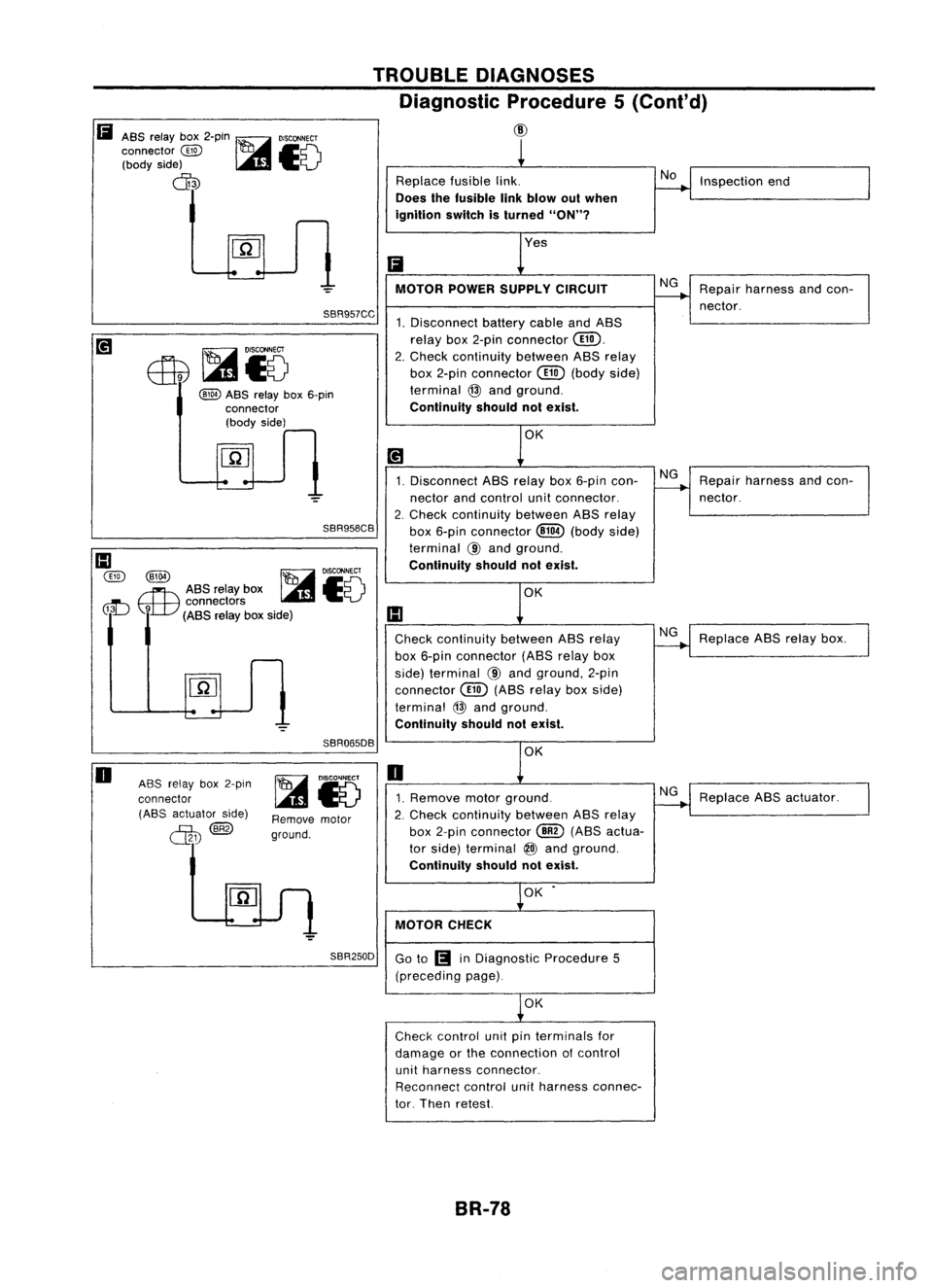
TROUBLEDIAGNOSES
Diagnostic Procedure5(Conl'd)
CID
Ii
ASS relay box2-pin ~
DISCONNECT
connector
@
=
1c0,
(body side)
V
cD
SBR957CC
@)
ASS relay box6-pin
connector (body side)
SBR958CB
III
@
@El ~
DISCONNECT
rrt\
ASSrelay box
~c;"1
\J.tV
connectors
-';;V
0U
9
(ASSrelayboxside) Replace
fusiblelink.
Does thefusible linkblowout when
ignition switchisturned
"ON"?
Ii
MOTOR POWERSUPPLVCIRCUIT
1. Disconnect batterycableandASS
relay box2-pin connector
@.
2. Check continuity betweenASSrelay
box 2-pin connector
@
(body side)
terminal @and ground.
Continuity shouldnotexist.
1. Disconnect ASSrelay box6-pin con-
nector andcontrol unitconnector.
2. Check continUity betweenASSrelay
box 6-pin connector @E)(body side)
terminal
@
and ground.
Continuity shouldnotexist.
OK
Check continuity betweenASSrelay
box 6-pin connector (ABSrelaybox
side) terminal @and ground, 2-pin
connector
@
(ASS relay boxside)
terminal @and ground.
Continuity shouldnotexist. No
NG
NG
NG
Inspection
end
Repair harness andcon-
nector.
Repair harness andcon-
nector.
Replace ASSrelay box.
J
o
ASSrelay box2-pin
connector (ASS actuator side)
~@
L1J.1J
SBR065DB
Remove motor
ground. OK
o
1. Remove motorground.
2. Check continuity betweenASSrelay
box 2-pin connector
@)
(ASS actua-
tor side) terminal
@)
and ground.
Continuity shouldnotexist. NG
Replace ASSactuator.
OK
MOTOR CHECK
SBR250D Goto
n!II
inDiagnostic Procedure5
(preceding page).
OK
Check control unitpinterminals for
damage orthe connection ofcontrol
unit harness connector.
Reconnect controlunitharness connec-
tor. Then retest.
BR-78
Page 349 of 1701
Fa
ASS relay box2-pin
DISCONNECT
connector
@~~~
(body side)
I..lI&I
~V
ctD
TROUBLE
DIAGNOSES
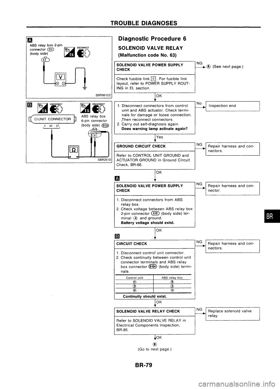
Diagnostic Procedure6
SOLENOID VALVERELAY
(Malfunction codeNo.63)
SOLENOID VALVEPOWER SUPPLY
CHECK
Check fusible link
@].
Forfusible link
layout, refertoPOWER SUPPLY ROUT-
ING inEL section.
NG
@
(See nextpage.)
~Io
( C/UNIT CONNECTOR
P
2 .30 .37
.
SBR961CC
ASS relay box
6-pin connector
(body side)
@W
Efe
OK
1. Disconnect connectors fromcontrol
unit andASS actuator. Checktermi-
nals fordamage orloose connection.
.Then reconnect connectors.
2. Carry outself-diagnosis again.
Does warning lampactivate again?
Yes
No
Inspection end
GROUND CIRCUITCHECK
Refer toCONTROL UNITGROUND and
SBR251D
ACTUATOR GROUNDinGround Circuit
Check, SR-66.
OK
SOLENOID VALVEPOWER SUPPLY
CHECK
1. Disconnect connectors fromASS
relay box.
2. Check voltage between ASSrelay box
2-pin connector
@
(body side)ter-
minal
@
and ground.
Battery voltage shouldexist.
CIRCUIT CHECK
1. Disconnect controlunitconnector.
2. Check continuity betweencontrolunit
connector terminalsandASS relay
box connector
@ill
(body side)termi-
nals. Repair
harness andcon-
nectors.
Repair harness andcon-
nector.
Repair harness andcon-
nectors.
•
Control unit
3T
ABS
relay box
Xi
@ @
Continuity shouldexist.
OK
SOLENOID VALVERELAY CHECK
Refer toSOLENOID VALVERELAY in
Electrical Components Inspection,
SR-85.
OK
@
(Go tonext page.)
BR-79
Replace
solenoid valve
relay.
Page 350 of 1701
~i5
TROUBLE
DIAGNOSES
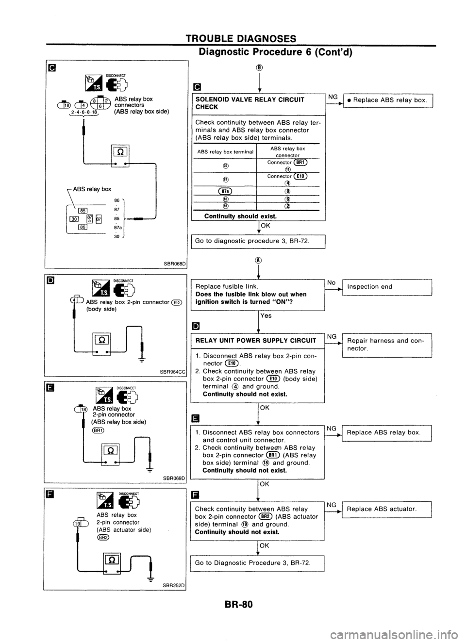
Diagnostic Procedure6
(Co nt'd)
(!)
1
~ ASSrelaybox
LI!ID
c:!D~
connectors
,2.4.~.8.18,
(ASSrelayboxside)
SOLENOID
VALVERELAY CIRCUIT
CHECK
NG
•Replace ASSrelay box.
Check continuity betweenASSrelay ter-
minals andASS relay boxconnector
(ASS relayboxside) terminals.
~SS relaybox
~
:~
}
[]QJ ~~
85
00
87a
30
ABS
relay boxterminal
87a
85
@
Continuity shouldexist.
OK
I
Go todiagnostic procedure3,SR-72.
SBR068D
I;]
~i5
Replace
fusiblelink. No
Inspection end
Does thefusible linkblowout when
GD
ASSrelay box2-pin connector
@
Ignition switchisturned
"ON"?
(body side)
Yes
I;]
[Q]
RELAYUNIT POWER SUPPLY CIRCUIT
NG
Repair harness andcon-
nector.
1. Disconnect ASSrelay box2-pin con-
-=-
nector@.
SBR964CC
2.
Check continuity betweenASSrelay
box 2-pin connector @(body side)
~i5
terminal
@
and ground.
Continuity shouldnotexist.
c1!D
ASS
relay box
OK
2-pin connector
Ii
(ASS relayboxside)
@ED
1.Disconnect ASSrelay boxconnectors NG
Replace ASSrelay box.
and control unitconnector.
2. Check continuity betwee"llASSrelay
box 2-pin connector
@
(ASS relay
box side) terminal
@
and ground.
-=-
Continuity
shouldnotexist.
SBR069D OK
Ii
~io
Ii
Check continuity betweenASSrelay NG
Replace ASSactuator.
@[)
ABS
relay box
box2-pin connector
@
(ASS actuator
2-pin connector
side)terminal
@
and ground.
(ABS actuator side)
Continuityshouldnotexist.
@
OK
Go toDiagnostic Procedure3,SR-72.
':"
SBR252D
BR-80
Page 353 of 1701

TROUBLEDIAGNOSES
Diagnostic Procedure10
SYMPTOM: Longstopping distance
Disconnect ABSrelay box6-pin connec- No
tor and check whether stopping dis-
tance isstill long.
Perform Preliminary Checkandair
bleeding. Go
to
IiJ
inDiagnostic
Procedure 11.SR-83.
Note: Stopping distancemaybelarger thanvehicles without
ABS when roadcondition isslippery.
Diagnostic Procedure11
SYMPTOM: Unexpected pedalaction
m
Check brakepedalstroke. Isstroke
excessively
large?
No
Disconnect ASSrelay box6-pin connec-
tor and check whether brakeiseffec-
SBR540A tive.
Yes
Ensure warning lampremains offwhile
driving.
OK
CHECK WHEEL SENSOR.
1. Check wheelsensor connector for
terminal damageorloose connec-
tion.
2. Perform wheelsensor mechanical
check. Refer to
IiJ
inDiagnostic Procedure
4, BR-75.
OK
Check control unitpinterminals for
damage orthe connection ofcontrol
unit harness connector.
Reconnect controlunitharness connec-
tor. Then retest.
BR-83
Yes
Perform Preliminary
Check. refertoSR-65.
Perform Preliminary
Check. refertoSR-65.
Carry outself-diagnosis.
Refer toBR-53 (Europe)
or SR-56 (Except
Europe).
Repair.
•
Page 355 of 1701
TROUBLEDIAGNOSES
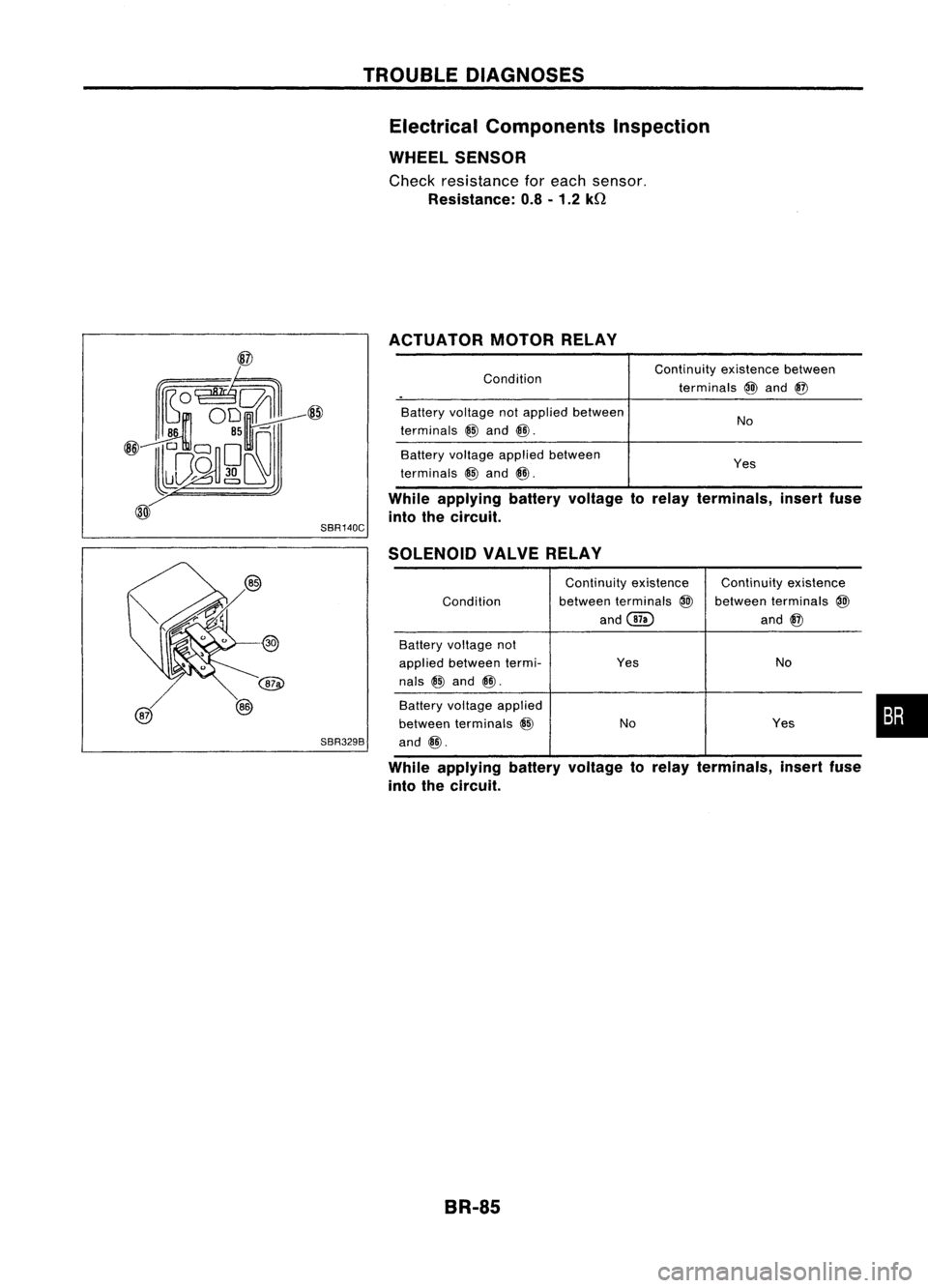
Electrical Components Inspection
WHEEL SENSOR
Check resistance foreach sensor.
Resistance: 0.8-1.2 kQ
ACTUATOR MOTORRELAY
While applying batteryvoltage torelay terminals, insertfuse
into thecircuit.
Condition
Battery voltage notapplied between
terminals
@
and
@.
Battery voltage applied between
terminals
@
and
@.
SBR140C
Continuity
existencebetween
terminals
@
and
@
No
Yes
SBR329B SOLENOID
VALVERELAY
Continuity existence Continuityexistence
Condition between
terminals
@
between terminals
@
and@ and
@
Battery voltage not
applied between termi- Yes
No
nals
@
and
@.
Battery voltage applied
between terminals
@
No Yes
and
@.
While applying batteryvoltage torelay terminals, insertfuse
into thecircuit.
BR-85
•
Page 373 of 1701
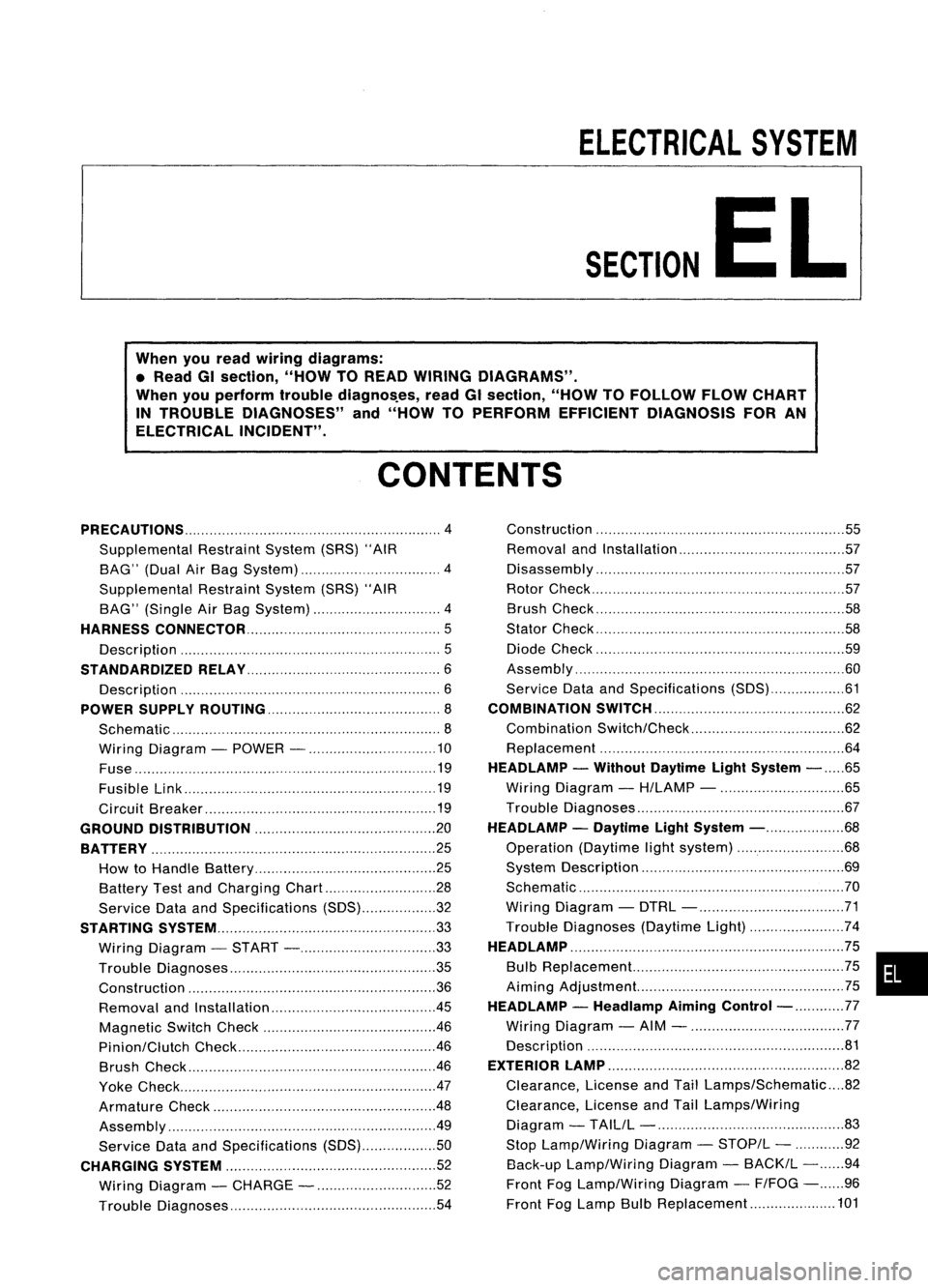
ELECTRICALSYSTEM
SECTION
EL
When youread wiring diagrams:
• Read GIsection, "HOWTOREAD WIRING DIAGRAMS".
When youperform troublediagnos.es, readGIsection, "HOWTOFOllOW FLOWCHART
IN TROUBLE DIAGNOSES" and"HOW TOPERFORM EFFICIENT DIAGNOSIS FORAN
ELECTRICAL INCIDENT".
CONTENTS
PRECAUTIONS 4
Supplemental RestraintSystem(SRS)"AIR
BAG" (DualAirBag System) 4
Supplemental RestraintSystem(SRS)"AIR
BAG" (Single AirBag System) 4
HARNESS CONNECTOR 5
Description 5
STANDARDIZED RELAy 6
Description 6
POWER SUPPLY ROUTING 8
Schematic 8
Wiring Diagram -POWER - 10
Fuse 19
Fusible Link 19
Circuit Breaker 19
GROUND DISTRIBUTION 20
BATTERy 25
How toHandle Battery 25
Battery TestandCharging Chart.. 28
Service DataandSpecifications (SOS) 32
STARTING SySTEM
33
Wiring Diagram -START - 33
Trouble Diagnoses 35
Construction 36
Removal andInstallation .45
Magnetic SwitchCheck .46
Pinion/Clutch Check 46
Brush Check 46
Yoke Check 47
Armature Check 48
Assembly .49
Service DataandSpecifications (SDS) 50
CHARGING SYSTEM 52
Wiring Diagram -CHARGE - 52
Trouble Diagnoses 54Construction
55
Removal andInstallation 57
Disassembly 57
Rotor Check 57
Brush Check 58
Stator Check 58
Diode Check 59
Assembly 60
Service DataandSpecifications (SDS) 61
COMBINATION SWITCH 62
Combination Switch/Check 62
Replacement 64
HEADLAMP -Without Daytime lightSystem -65
Wiring Diagram -H/LAMP - 65
Trouble Diagnoses 67
HEADLAMP -Daytime lightSystem - 68
Operation (Daytimelightsystem) 68
System Description 69
Schematic 70
Wiring Diagram -DTRL - 71
Trouble Diagnoses (DaytimeLight) 74
HEADLAMP 75
Bulb Replacement... 75•
Aiming Adjustment. 75
HEADLAMP -Headlamp Aiming
Control- 77
Wiring Diagram -AIM - 77
Description 81
EXTERIOR LAMP 82
Clearance, LicenseandTail Lamps/Schematic 82
Clearance, LicenseandTail Lamps/Wiring
Diagram -TAILIL - 83
Stop Lamp/Wiring Diagram-STOP/L - 92
Back-up Lamp/Wiring Diagram-BACK/L -94
Front FogLamp/Wiring Diagram-F/FOG -96
Front FogLamp BulbReplacement 101
Page 377 of 1701

Packing(Water-proof type)
HARNESS
CONNECTOR
Description
HARNESS CONNECTOR
• Allharness connectors havebeen modified toprevent accidental loosenessordisconnection.
• The connector canbedisconnected bypushing orlifting thelocking section.
CAUTION: Do not pull theharness whendisconnecting theconnector.
[Example]
LIFT PUSH
PUSH
PUSH
(For combination meted
EL-5
PUSH
(For relay)
SEL769D
•
Page 378 of 1701

STANDARDIZEDRELAY
Description
NORMAL OPEN,NORMAL CLOSEDANDMIXED TYPERELAYS
Relays canmainly bedivided intothree types: normal open,normal closedandmixed typerelays.
MIXED TYPERELAY
Does note:>
flow. Flows
.
•
Flows.
NORMAL
CLOSEDRELAY
=
I
=
I
0
0
SW 1
BATIERY SW
1
BATIERY
Does not Does
not
flow.
Q
flow.
Q
=
Flows.
t
L
I
SW
1
BATIERY BATIERY
NORMAL
OPENRELAY
Does not
U.
flow.
e:>
=
u.
9
~
(J)
I
BATIERY
Flows .
•
Z
0
:s:
L
(J)
SW1
BATIERY
SEL881H
TYPE OFSTANDARDIZED RELAYS
1M1T
1
Make
1 Transfer
2M
1M.1B
2
Make
.................. 1Make 1Break
r~~-~.~_._- -~--_.-_.." ..__ ._-~- _.. ----------- -------~.- -.----.-----~----
1M
1M
2M
(ftj
,
,
..
"
2M
r---~--- .-------------
; 1T
r-~~- -~.-----.- ---- ....
1T I
(/ -',\ I
~.. --_\_~- ~---- j
iM.1B
1B
SEL882H
EL-6
Page 379 of 1701

51ANDARDIZED RELAY
Description (Cont'd)
Type Outer
view
CircuitConnector
symbol
and connection Case
color
•
GRAY
BLUE
BROWN
=
=
2M 1T
BLACK
1M
1M.1B
The arrangement ofterminal numbers onthe actual relaysmaydiffer fromthose shown above.
SEL661TA
EL-7
Page 381 of 1701

POWERSUPPLY ROUTING
Schematic (Cont'd)
l5A~
F/FOG
20A
@J
LOAD,DEF
lOA
[8J
ABS,SToP/L
lOA
[ill
TURN
FICO, A!CCUT,
HEATER, A!e
HEATER, A!e
7.5A@Q]
lOA
@]
l5A
[ill
INT/L
GLOW, AIM,BUZZER,
HORN, AUDIO, NATS
ILL, AUDIO
WIP/R
ACCESSORY
RELAY
20A
[ill
lOA ~
l5A ~ HORN
WIPER
MIRROR, DEF
HLC
20A []]
•
LOAD,
DEF
LOAD, MIL,BUZZER, WINDOW,
SROOF, DEF,NATS
LKUP, AIT,BACK/L,
METER, WARN
TURN
ABS
H/SEAT
H02S
F/PUMP, AIRREG
SRS
SRS
PGC/V, EGRC/V, AAC/V,VTC,
COOL/F, LOAD,GLOW,PLA,
FCUT, A/C,START, DTRL,DEF
3A
IE]
lOA
[ill
lOA
[ill
lOA ~
l5A
@]
7.
5A
[ill
n
IGNITION
U
RELAY
TAIL. F/FoG
LOAD, AIM,TAIL, F/FO~
ILL, BUZZER
RHO
models
eo engine
SR engine
SR engine A/Tmodels
and COengine
For Europe andIsrael
Except
@
LHD models without
daytime lightsystem
Except
@
LHo models with
daytime lightsystem
Without daytime lightsystem
With single airbag system
With dualairbag system
@
@
@
@
@
@
@
@
@
@
@
@)
HEL096
EL-9