stop start NISSAN ALMERA N15 1995 Owner's Manual
[x] Cancel search | Manufacturer: NISSAN, Model Year: 1995, Model line: ALMERA N15, Model: NISSAN ALMERA N15 1995Pages: 1701, PDF Size: 82.27 MB
Page 414 of 1701

STARTINGSYSTEM
Construct"
IOn
(Cont'd)
U;it: mm(in)
[iJ:
N.m(k
B(8J:
Hih- g.m, in-Ib)
9 temperature grease.
pOint
@
Plate thickness'
~.25 (...... ;
ijJ
25...
. 50 (0'0197)\~
b
3
(0.25.'0.45 2
9
•1.7. 39.1)
7 8 •
iji...
7.1
IiiiI .,
0
(0.4'•
'.72
"'" '.1•7.'
s;i:
39.1•02 ')'
(0 ••
2.
'.77
@
ijJ
10-12 .
(8JB ~
':>
87.104)
<,\\:~'
~ IOI!Ei!@ ,
~., Jtlj)~
EIl@ .
I~~~
6 ,,,'
Q)
@
@
@
@
@
(j)
Sleeve
bea.
ring
Gear case
Stopper cr
P'
Ip
p~n!on stopper
mlon assembl
Internal gY
, ear
ShIft lever
@
@
@)
@
@
@
@
Plate
Packing
PI~netary gear
Adjusting plate
Magnetic swith
Packing cassembly
Yoke
Armature
Bush
(+)
Brush spring
Brush holder
Bearing
Rear cover
SEC. 233
S114-806
MEL675EA
iji:
N.m (k
m
tj:f"
g-m,in-Ib)
\!:y'
Hlgh-tem
greas p,erature
e
POint
EL-42
Page 416 of 1701

STARTINGSYSTEM
Construction (Cont'd)
@Plate thickness:
0.25 (0.0098)
0.50 (0.0197)
SEC.
233
M2T49282
SEL526QB
CD
Gear
casemetal
@
Shift lever
@
Yoke
@
Gear case
(J)
Holder
@
Brush
(+)
@
Stopper clip
@
Armature
@
Brush spring
@
Pinion stopper
@
Adjusting plate
@
Brush (-)
@
Pinion assembly
@)
Magnetic switchassembly
@
Rear cover
SEC. 233
S114-570B
Dustcover (Adjusting Plate
1)
Plate thickness:
~ 6.4-7.8 0.5(0.020)
(0.65 -0.80, 56.4.69.4) 0.8(0.031)
~onnector stayset Torsion sprrng\
Dust cover
00
0Jl
0
0
Gear casemetal
m
@
Unit :mm (in)
~: N.m
(kg-m, in-Ib)
m
(8J:
High.temperature greasepoint Magnetic
switchassembly
r~7.4 -
9.8 (0.75 -1.00,65.1 .86.8)
~4.9 -
6.4
(0.50 -0.65, 43.4-56.4)
E-ring
Rear cover metal
m
@
Brush
H
Brush
(+)
MEL674E
EL-44
Page 421 of 1701

[
"T"
,
,
I
-L.
Type 1
Type 2
Type 3
Clearance
"
!2 "
SEL026Z
,.
~"'ti"g
pl."
~ ~
~o'IJ
III III
A:iusting plate
,.~
~.
Adjusting plate
SEL029Z STARTING
SYSTEM
Assembly
Apply high-temperature greasetolubricate thebearing, gears
and frictional surfacewhenassembling thestarter.
Carefully observethefollowing instructions.
PINION PROTRUSION LENGTHADJUSTMENT
With pinion driven outbymagnetic switch,pushpinion backto
remove slackandmeasure clearance''£'' betweenthefront
edge ofthe pinion andthepinion stopper.
Clearance
"-E":
Refer to50S
(EL-SO).
• Not inthe specified value.., Adjust byadjusting plate.
EL-49
•
Page 422 of 1701

STARTINGSYSTEM
Service DataandSpecifications (SDS)
STARTER
S114-766A M1T72087A
M1T77281S114-769A S114-630M3T37783 M2T62071A S13-305S13-331M2T61871A
Type HITACHIMITSUBISHI HITACHI
MITSUBISHI HITACHIMITSUB-
ISHI
Reduction Non-reduction
Reduction
Europe
Applied model
GAengines
CD20
A/T MIT
System voltage
V
12
No-load Terminal voltage
V
11.0 11511.0
Less than
50-75 Less
than
Lessthan60 Less
than
Lessthan140 Less
than
Current A
85 85105110
More than Morethan More
Morethan More
than Morethan
Revolution rpm
2,950 3,000
-4,000
2,950than
6,500 4,030More
than3,900
4,100
7,000
Minimum diameterof 28.0
28.8(1.134) 28.0
39.0
31.4(1.236) 35.5(1.398) 31.4
commutator mm(in) (1,102) (1,102)(1.535) (1236)
Minimum length
10.5 10.511.0
11.5(0.453) 11.0
(0.433) 11.5
of brush mm(in) (0.413) 12.0
(0.472)
(0.413)(0.433) (0.453)
16.2 14.7
-17.7 17.7
-
13.7-25.5
Brush spring tension
(1.65, 13.7
-25.5
(1.5-1.8, 21.6
13.7-25.5 28.4
-34.3 (2.90 -
(1.4 -2.6,
N (kg, Ib)
3.64) (1.4
-2.6, 3.1-5.7)
3.3-4.0) (1.8
-2.2, (1.4-2.6, 3.1-5.7) 3.50,
6.38-7.71)
3.1-5.7)
4.0 -4.9)
Clearance between
Lessthan Less
Less
bearing metaland
-
than0.2
-
than
0.2
-
armature shaftmm(in) 0.2
(0.008)
(0.008) (0.008)
Clearance
'T'
0.3-2.5 0.5
-2.0 0.3-2.0 0.3
-0.8
between pinionfront
(0.012- 0.5
-2.0 0.3-2.5
(0.020- (0.012
-(0.012 -
- -
edge andpinion
0.098)(0.020
-0.079) (0.012
-0.098)
0.079) 0.079)0.031)
stopper mm
(in)
Movement
'T'
in 0.5
-2.0 0.3
-1.5
height ofpinion
-
(0.020
-
-
-
(0.012
-
assembly mm(in) 0.079)0.059)
EL-50
Page 423 of 1701

STARTINGSYSTEM
Service DataandSpecifications (SOS)(Cont'd)
M1T72985A S114-806S114-800A
MOT80281ZC
I
MOT80281 M2T49282
S114-568A
I
S114-570B M2T48681
Type MITSUB-
HITACHI MITSUBISHI HITACHIMITSUB-
ISH I ISHI
Reduction Non-reduction
Australia RHD
Except Europe andAustralia
Applied model GA
engines
SR20DE
I
A/T
M/T
AIT
System voltage
V
12
No-load Terminal voltage
V
11.0 11.5
Current A50-75 Less
than90 Less
than
Lessthan60 Less
than
53 53
3,000 - More
.
Revolution rpm
4,000 than
More
than2,750 Morethan6,000
2,700
Minimum diameterof 28.8
280(1.102) 28.8(1.134) 314
28.0(1.102) 314
commutator mm(in) (1.134)
(1.236)
(1236)
Minimum length 12.0
10.5(0413) 7.0
(0.276) 11.5
90(0.354) 11.5
of brush mm(in) (0472) (0453)
(0453)
Brush spring tension 13.7
-25.5
12.7-17.7 11.77-23.53 13.7
-25.5
9.8-13.7 137
-25.5
(14 -2.6, (14
-2.6, (1.4-2.6,
N (kg, Ib)
3.1-5.7) (1.3
-1.8, 2.9-4.0) (1.2-24, 2.6-5.3)
3.1-5.7) (1.0
-14, 2.2-31)
3.1.5.7)
Clearance between
bearing metalandarma- Lessthan0.2(0.008)
ture shaft mm(in)
Clearance"
C"
0.5-2.0 0.5
-2.0
between pinionfront
(0.020- 0.3
-25
05-2.0 (0.020 -0.079) 0.3-2.5 (0.012 -0.098) (0.020-
edge andpinion
0.079)(0.012
-0.098)
0.079)
stopper mm
(in)
Movement
'T'
in
heigh\. atpinion
-
assembly
mm(in)
EL-51
•
Page 440 of 1701
HEADLAMP-Daytime LightSystem -
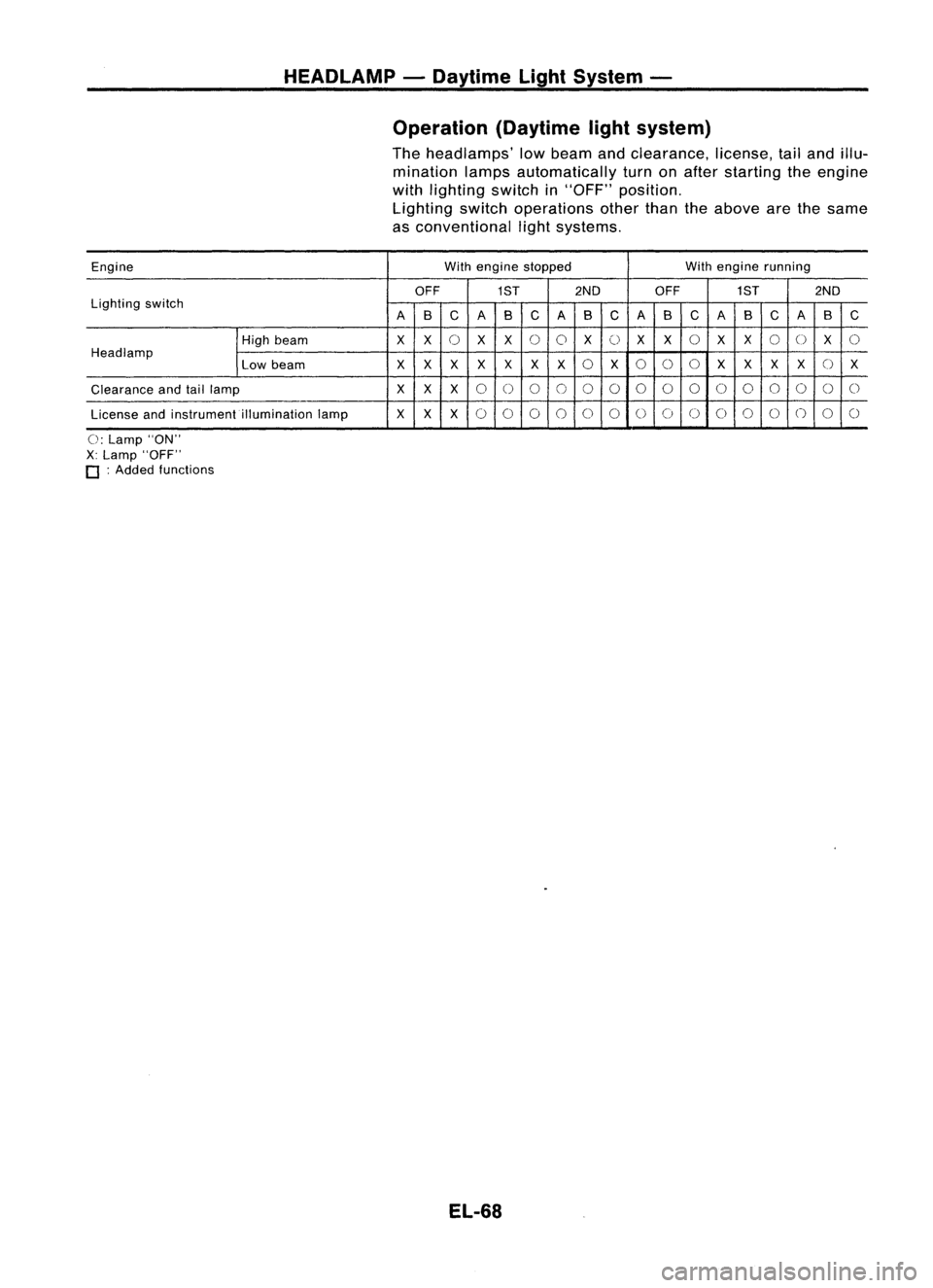
Operation (Daytimelightsystem)
The headlamps' lowbeam andclearance, license,tailand illu-
mination lampsautomatically turnonafter starting theengine
with lighting switchin"OFF" position.
Lighting switchoperations otherthantheabove arethesame
as conventional lightsystems.
Engine With
engine stopped Withengine running
OFF
1ST2ND
OFF
1ST2ND
Lighting switch
B
C
A
B
C
B
C
A
B
C
B
C
A
B
C
A AA
High beam
XX
0
X
X
0
0
X
0
X
X
0
XX
0
0
X
0
Headlamp
0
0
()
0
()
Low beam
X
XX
XX
X
X
X
XXXX X
Clearance andtaillamp
X
XX
0
0
0
0
00
0
0
0
0
00
0
0
0
License andinstrument illumination lamp
X
XX
0 0
0
0
0
0
0
0 00
0
0()
0
0
0: Lamp "ON"
X: Lamp "OFF"
o :
Added functions
EL-68
Page 446 of 1701
HEADLAMP-Daytime LightSystem -
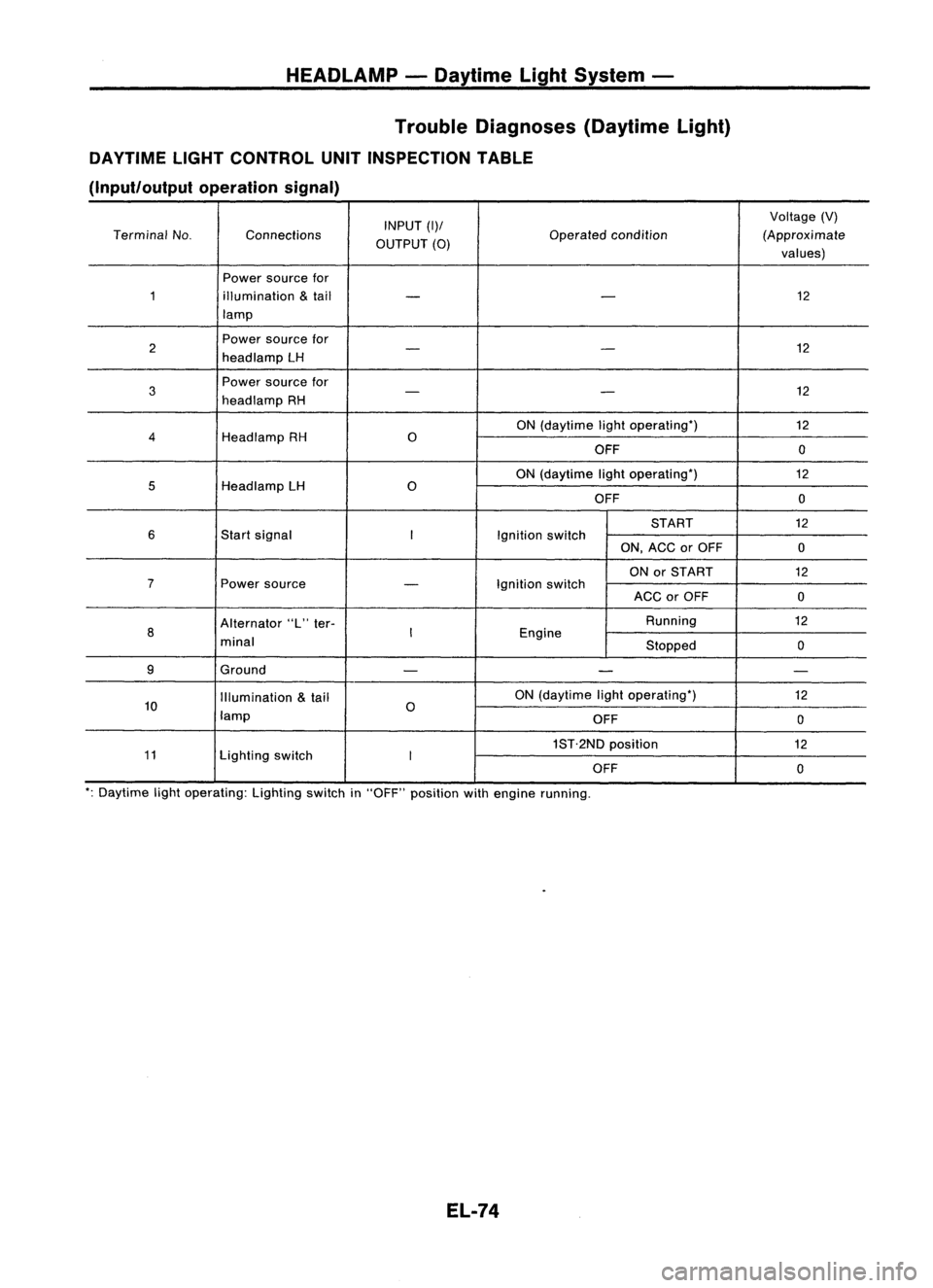
Trouble Diagnoses (DaytimeLight)
DAYTIME LIGHTCONTROL UNITINSPECTION TABLE
(Input/output operationsignal)
INPUT
(1)/
Voltage
(V)
Terminal No. Connections
OUTPUT
(0)
Operated
condition (Approximate
values)
Power source for
1 illumination
&
tail
- -
12
lamp
2 Power
source for
12
- -
head lamp LH
3
Power
source for
12
-
-
head lamp RH
ON(daytime lightoperating')
12
4
HeadlampRH
0
OFF 0
ON (daytime lightoperating') 12
5
HeadlampLH
0
OFF 0
START 12
6
Startsignal
I
Ignitionswitch
ON,ACC orOFF
0
ON orSTART
12
7
Powersource
-
Ignition
switch
ACCorOFF
0
Alternator "L"ter- Running
12
8
I
Engine
minal Stopped0
9 Ground
- - -
Illumination
&
tail ON
(daytime lightoperating')
12
10 lamp
0
OFF 0
1ST.2ND position
12
11 Lightingswitch
I
OFF 0
': Daytime lightoperating: Lightingswitchin"OFF" position withengine running.
EL-74
Page 453 of 1701

HEADLAMP-Headlamp AimingControl -
Reversing
relay
Thermistor
Reversing
relay
Thermistor
Reversing
relay
::- Thermistor
+
BATIERY
A o
1
2
3
SEL465M
+
BATIERY
o
1
2
3
SEL364P
+
BATIERY
o
1
2
3
SEL365P Description
CIRCUIT OPERATION
[Example]
Aiming switch
"0"
• When theaiming switchisset to"0", themotor willnotstart.
This isbecause thepower terminals arepositioned atthe
nonconductive sectionofthe sensor's rotaryunit.
Aiming switch
"0"
-t
"1"
• When theaiming switchismoved from"0"to"1", thesen-
sor's conductive sectionactivates therelay. Power issup-
. plied through therelay tothe motor. Theheadlamps will
then move inthe "DOWN" direction.
• The motor continues torotate whiletherotary unitofthe
sensor movesfrompoint Ato point B.
• The power terminals willthen bepositioned atthe noncon-
ductive section, disconnecting thepower tothe motor. The
motor willthen stop.
Aiming switch"1"
-t
"0"
• When theaiming switchismoved from"1"to"0", thesen-
sor's conductive sectionactivates therelay. Power issup-
plied through therelay tothe motor. Themotor willrotate
to move theheadlamps inthe "UP" direction.
• When therotary unitofthe sensor movesfrompoint Bto
point A,the motor willstop.
EL-81
•
Page 523 of 1701

Ohmmeter- + WARNING
LAMPSANDBUZZER
Oil Pressure SwitchCheck
Oil pressure
Continuity
kPa (bar, kg/cm
2,
psi)
More than10-20
NO
Engine
start
(0.10-0.20, 0.1-0.2, 1.4-2.8)
Less than10-20
YES
Engine
stop
(0.10-0.20, 0.1-0.2, 1.4-2.8)
SEL748K
Test lamp 3.4WON
\ ,I
"
/
Ballery
Test lamp 3.4W OFF
~0
CD
Ballery
Gasoline MEL623D
SEL901F
Check
thecontinuity betweentheterminals ofoil pressure
switch andbody ground.
Fuel Warning LampSensor Check
• Itwill take ashort timeforthe bulb tolight.
Diode Check
• Check continuity usinganohmmeter.
• Diode isfunctioning properlyiftest results areasshown in
the figure atleft.
NOTE:
Specification mayvary depending onthe type oftester. Before
performing thisinspection, besure torefer tothe instruction
manual forthe tester tobe used.
• Diodes forwarning lampsarebuilt intothecombination
meter printed circuit.
Refer to"Combination Meter"(EL-127).
Warning BuzzerUnit
• Seat beltwarning lampiscontrolled bythe warning buzzer
unit.
Refer to"Warning Buzzer"(EL-152).
EL-151
•
Page 551 of 1701
.WIPER ANDWASHER
SEL244P Headlamp
WiperMotorCheck
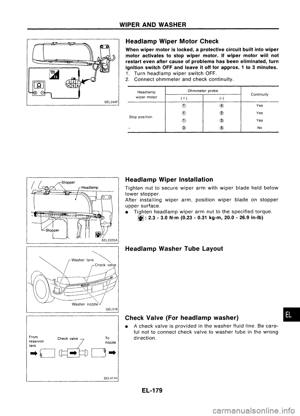
When wiper motor islocked, aprotective circuitbuiltintowiper
motor activates tostop wiper motor. Ifwiper motor willnot
restart evenaftercause ofproblems hasbeen eliminated, turn
ignition switchOFFandleave itoff for approx. 1to 3minutes.
1. Turn headlamp wiperswitch OFF.
2. Connect ohmmeter andcheck continuity.
Headlamp Ohmmeter
probe
Continuity
wiper motor
(+)
H
(!) @
Yes
(!)
@
Yes
Stop position
(!)
CID
Yes
.
CID
@)
No
From
.. 0
c~'..
~'fo
reservoir
tank GEL018
To
nozzle
0"
SEL411H Headlamp
WiperInstallation
Tighten nuttosecure wiperarmwith wiper bladeheldbelow
lower stopper.
After installing wiperarm,position wiperbladeonstopper
upper surface.
• Tighten headlamp wiperarmnuttothe specified torque.
~ :2.3 -3.0 N'm (0.23 -0.31 kg-m, 20.0-26.9 in-Ib)
Headlamp WasherTubeLayout
Check Valve(Forheadlamp washer)
• Acheck valveisprovided inthe washer fluidline.Becare-
ful not toconnect checkvalvetowasher tubeinthe wrong
direction.
EL-179
•