key NISSAN ALMERA N15 1995 Owner's Guide
[x] Cancel search | Manufacturer: NISSAN, Model Year: 1995, Model line: ALMERA N15, Model: NISSAN ALMERA N15 1995Pages: 1701, PDF Size: 82.27 MB
Page 1109 of 1701
TROUBLEDIAGNOSES
Quick-glow System
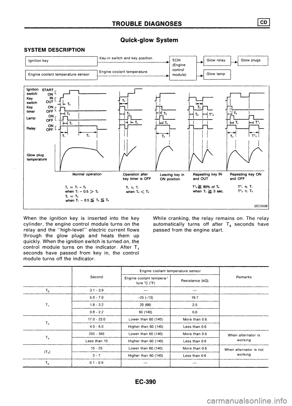
SYSTEM DESCRIPTION
Ignition key
Engine coolant temperature sensorKey-in
switch andkeyposition
Engine coolant temperature
ECM
(Engine
control
module) Glow
relay
Glow lamp Glow
plugs
Ignition START[~
~
switch
~~[ I
11
I
1iI
Key
~
switch OUT
-II-
T,
I
!
I
I-l
Key ONe
n
Hn
JTl-
.1"l....!:.1L-
~
timer
OFF
Ir1
To
I
UL
HTo
HT'o
Lamp ON
[
..Lfl
o~~
I
I-.J
TL
I
~
I
I-l
TL
I
I
I
I
I
HTL
I-l
T'L
Relay OFF
[j
I_
L-
r--L
.f"l.-.JL
~
T.
"'
II
I
II
~
1r;,1
I II I
I,
Glow plug
temperature
Normaloperation
Operationafter
key timer isOFF Leaving
keyin
ON position Repeating
keyIN
and OUT Repeating
keyON
and OFF
TL
=
T,-T,
when T,-0.5 >T,
TL
= T,
when T,-0.5 ~T,
;a;
To
TL
=.
T,
when To
<
T, T'o
~80% ofTo
when T.
5':
3sec.
T',
=.
T,
T',
=.
T,
SEC550B
When theignition keyisinserted intothekey
cylinder, theengine control module turnsonthe
relay andthe"high-level" electriccurrentflows
through theglow plugs andheats themup
quickly. Whentheignition switchisturned on,the
control module turnsonthe indicator. AfterT
1
seconds havepassed fromkeyin,the control
module turnsoffthe indicator. While
cranking, therelay remains on.The relay
automatically turnsoffafter T
4
seconds have
passed fromtheengine start.
Engine coolant temperature sensor
Second Enginecoolant tempera-' Remarks
ture 'C('F) Resistance
(kQ)
To
3.1
-3.9
- -
5.0 -7.0 -25(-13)
19.7
T,
1.8
-3.2
20(68)
2.5
0.8 -2.2 60(140)
0.6
17.0 -23.0
Lowerthan
60(140)
Morethan
0.6
T
3
40-6.0
Higherthan
60(140)
Lessthan
0.6
255 -345
Lowerthan
60(140)
Morethan
0.6
Whenalternator is
T
4
working
Less than
10
Higherthan
60(140)
Lessthan
0.6
15 -25
Lowerthan
60(140)
Morethan
0.6
Whenalternator isnot
(T
4)
working
3 -7
Higherthan
60(140)
Lessthan
0.6
T
5
0.1-0.9
- -
EC-390
Page 1110 of 1701
TROUBLEDIAGNOSES
Quick-glow System(Cont'd)
DESCRIPTION
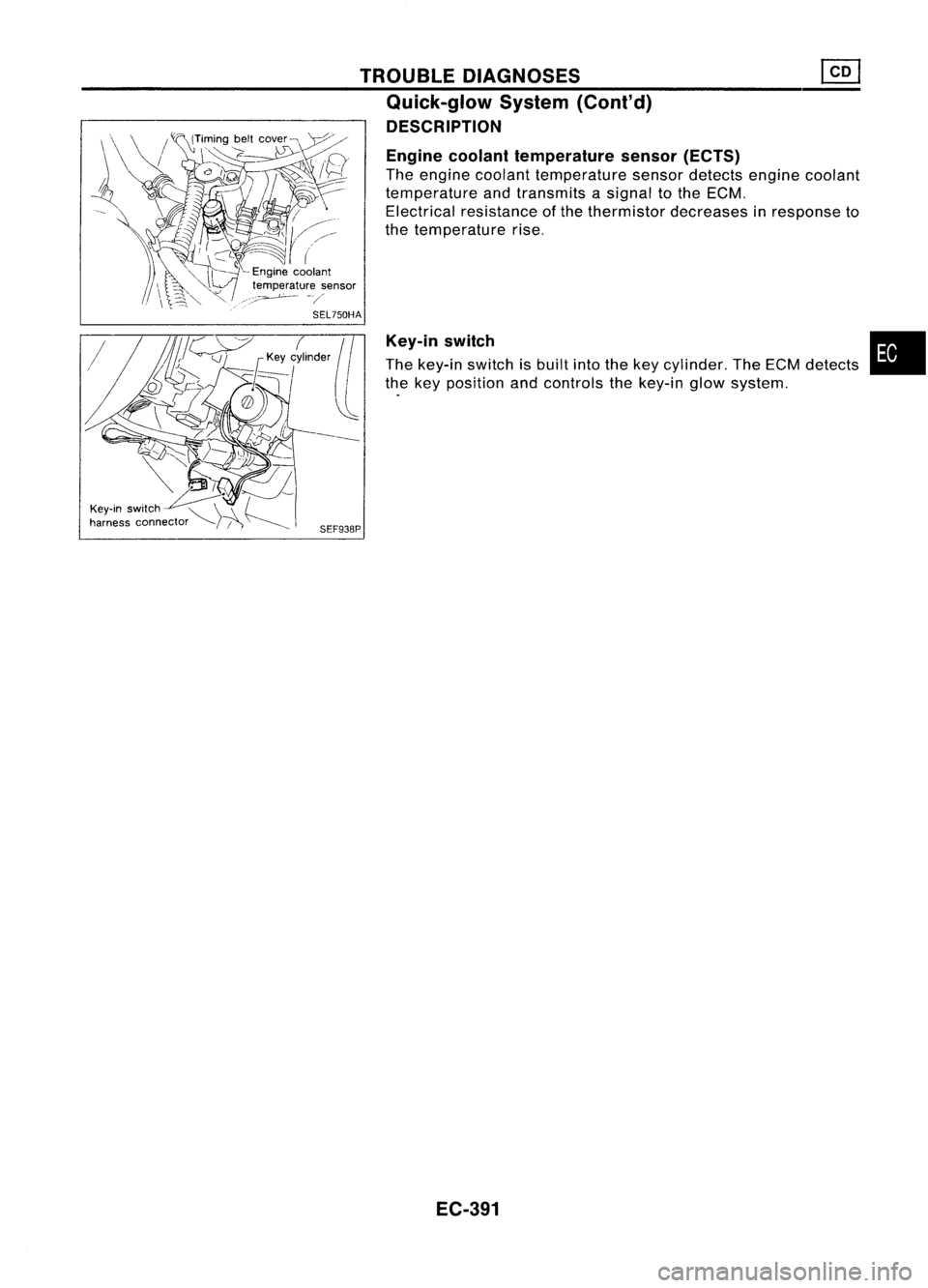
Engine coolant temperature sensor(ECTS)
The engine coolant temperature sensordetects enginecoolant
temperature andtransmits asignal tothe ECM.
Electrical resistance ofthe thermistor decreases inresponse to
the temperature rise.
Key-in switch
The key-in switch isbuilt intothekey cylinder. TheECM detects
the key position andcontrols thekey-in glowsystem.
SEF938P
EC-391
•
Page 1112 of 1701
![NISSAN ALMERA N15 1995 Owners Guide TROUBLEDIAGNOSES
Quick-glow System(Cont'd)
•
GLOW
PLUG
(E213)
R
ctJ@
~~
R
I
R
Q
(b):
LHDmodels
<E:>:
RHOmodels
EC-GLDW-02
Refer toEL-POWER.
75A
IT]
!'e"
(ENGINE
CONTR](/img/5/57349/w960_57349-1111.png "NISSAN ALMERA N15 1995 Owners Guide TROUBLEDIAGNOSES
Quick-glow System(Cont'd)
•
GLOW
PLUG
(E213)
R
ctJ@
~~
R
I
R
Q
(b):
LHDmodels
<E:>:
RHOmodels
EC-GLDW-02
Refer toEL-POWER.
75A
IT]
!'e\"
(ENGINE
CONTR")
TROUBLEDIAGNOSES
Quick-glow System(Cont'd)
•
GLOW
PLUG
(E213)
R
ctJ@
~~
R
I
R
Q
(b):
LHDmodels
RHOmodels
EC-GLDW-02
Refer toEL-POWER.
75A
IT]
!'e"
(ENGINE
CONTROL
MODULE)
(M39)
W/L
B/R
1--~
I
W!L B/R
11!11~II~e~y
~m>
~
1!:i=Jll!:i=!J~
W/R R
I
~1
W/R W/R
CHID ~ I~ICHID
W/R W/R
tJ
I
W/R
IL@JI
G/R
+f
W/L W/L
m
rA,
~(E10f)
CHID I~I
I~ICHID
W/L W!L
tJ
I
W/L
1001
BATT
FUSE
BLOCK
(JIB)
(106)
7.5A
1241
I
BATTERY
I
•
. ------.
~ffij
10.
91
P
I
P
~1
KEY-IN
IN SWITCH
OUT--
@
~
BR/Y
I
~~
BR/Y BR/Y
(E10f) .~ ~(EiOf)
CHID
I~I
I~ICHID
BR/Y BR/Y
t-t
I
BR/Y
00 KEY
~ (E115)
[IIg]
W
~---------------~
I I
:Fnm>~~~~:
:rnJ
G
@J
W
l.9J
W:
, ,
-----------------
Refer
tolast page
(Foldout page).
HEC089
EC-393
Page 1114 of 1701
TROUBLEDIAGNOSES
Quick-glow System(Cont'd)
@
CHECK COMPONENTS NG
(Glow relay, Glowplug,Engine coolant
temperature sensor,Key-inswitch, Igni-
tion switch).
Refer to"Component Inspection"(EC-
397).
OK
Disconnect andreconnect harnesscon-
nectors inthe circuit. Thenretest.
Trouble isnot fixed.
Check ECMpinterminals fordamage or
the connection ofECM harness connec-
tor. Reconnect ECMharness connector
and retest. Replace
malfunctioning
component(s).
•
BATIERY [
Voltage
OV
Ignition
key
START
[
ON
IN [
OUT
,
,
,
I
,
JL
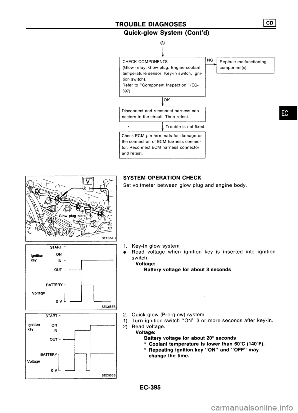
SEC5558SYSTEM
OPERATION CHECK
Set voltmeter betweenglowplugandengine body.
1. Key-in glowsystem
• Read voltage whenignition keyisinserted intoignition
switch.
Voltage: Battery voltage forabout 3seconds
Ignition
key
BATIERY [
Voltage
OV
SEC5568
2.
Quick-glow (Pre-glow)system
1) Turn ignition switch"ON"3or more seconds afterkey-in.
2) Read voltage.
Voltage: Battery voltage forabout 20*seconds
*
Coolant temperature islower than60°C(140°F).
* Repeating ignitionkey"ON" and"OFF" may
change thetime.
EC-395
Page 1115 of 1701
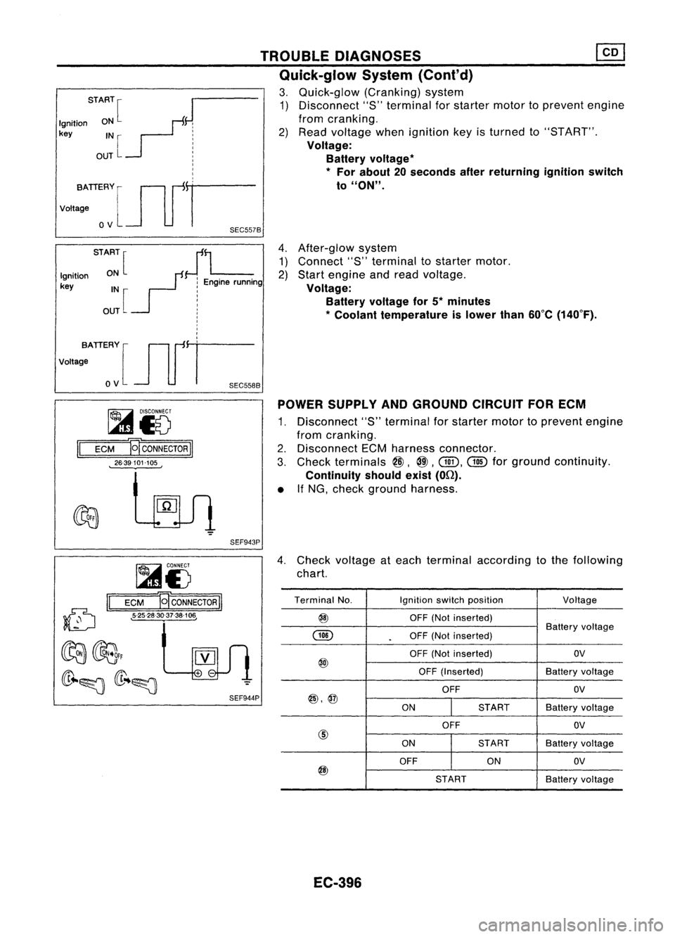
4.After-glow system
1) Connect "8"terminal tostarter motor.
2) Start engine andread voltage.
Voltage: Battery voltage for5*minutes
* Coolant temperature islower than60°C(140°F).
TROUBLE
DIAGNOSES
Quick-glow System(Cont'd)
3. Quick-glow (Cranking)system
1) Disconnect "S"terminal forstarter motortoprevent engine
from cranking.
2) Read voltage whenignition keyisturned to"8T ART".
Voltage: Battery voltage
*
*
For about 20seconds afterreturning ignitionswitch
to
"ON".
START
[
J
Ignition ON
F:
key IN
r- j
OUT
L :
I
I
I
vo,,:TIERYlJlfr
o
V
SEC557B
STA:~[
JL
Ignition
r:
Enginerunning
key IN :
OUT [
!
I
I
,
I
,
votta;ATIERY [Jlfi=
o
V
SEC558B
~i5
II
ECM E
CONNECTOR
II
26-39101-105 POWER
SUPPLY ANDGROUND CIRCUITFORECM
1. Disconnect "S"terminal forstarter motortoprevent engine
from cranking.
2. Disconnect ECMharness connector.
3. Check terminals
@,
@.
Gill.
@
forground continuity.
Continuity shouldexist(On).
• IfNG, check ground harness.
SEF943P
(D
II
~i5
ECM B
CONNECTOR
II
• 5-25-28-30-37-38-106,
4.
Check voltage ateach terminal according tothe following
chart.
Terminal No. Ignitionswitchposition
Voltage
@
OFF(Notinserted)
GID
Battery
voltage
.
OFF
(Notinserted)
OFF (Not inserted) OV
@
OFF(Inserted) Batteryvoltage
OFF OV
@,@
ONSTARTBatteryvoltage
OFF OV
@
ONSTART
Batteryvoltage
OFF ONOV
@
STARTBatteryvoltage
EC-396
Page 1116 of 1701
TROUBLEDIAGNOSES ~
Quick-glow System(Cont'd)
• If
NG.
check component partsandtheir related harness
according tothe following chart.
Parts which should bechecked
Terminal Fuse Glowin-
No. Battery IFusible Glow
Key-in Ignition
dicatorHarness
link relay
switch switch
bulb
@
XX
X
@
X
X X X
@
XX
X X
@,@
XX XX
@
XX X
X X
@
X
X XX
COMPONENT INSPECTION
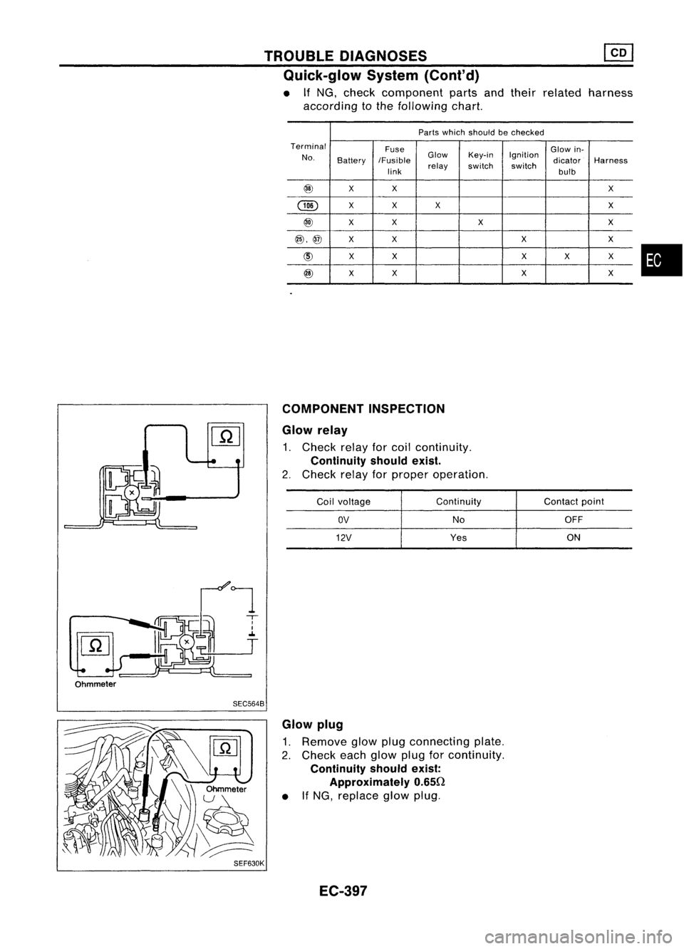
Glow relay
1. Check relayforcoil continuity.
Continuity shouldexist.
2. Check relayforproper operation.
Coil voltage Continuity
Contactpoint
OV
NoOFF
12V
Yes ON
•
Ohmmeter SEC5648
SEF630K Glow
plug
1. Remove glowplugconnecting plate.
2. Check eachglow plugforcontinuity.
Continuity shouldexist:
Approximately 0.650
• IfNG, replace glowplug.
EC-397
Page 1117 of 1701
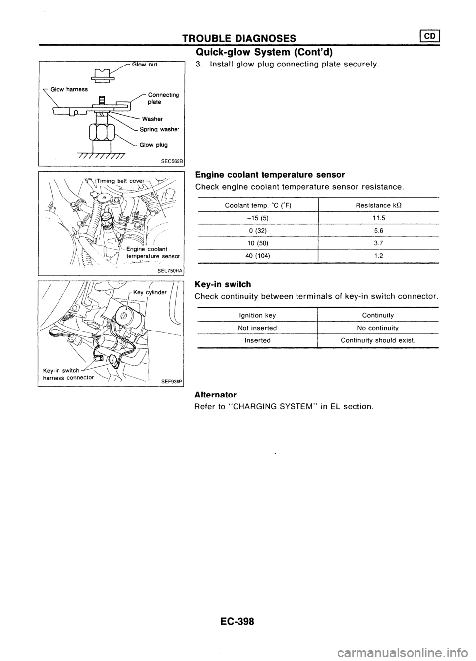
SEC5658Enginecoolant temperature sensor
Check engine coolant temperature sensorresistance.
Key-in switch
Check continuity betweenterminals ofkey-in switch connector.
11.5
5.6
3.7
1.2
Resistance
kfl
Continuity
No continuity
Continuity shouldexist.
Ignition
key
Not inserted
Inserted
Coolant
temp.°C('F)
-15 (5)
0(32)
10 (50)
40 (104)
TROUBLE
DIAGNOSES
Quick-glow System(Cont'd)
3. Install glowplugconnecting platesecurely.
Connecting
plate
Spring washer
~GIOwnut
Glow harness
Alternator
Refer to"CHARGING SYSTEM"inEL section.
EC-398
Page 1202 of 1701
TIMINGCHAIN
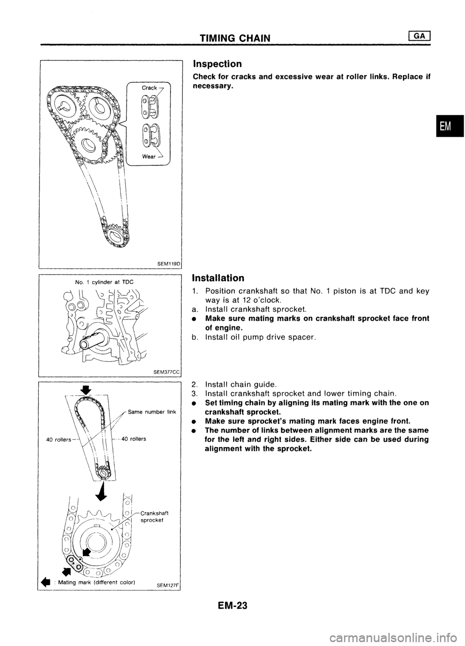
Inspection
Check forcracks andexcessive wearatroller links.Replace if
necessary.
•
SEM1190
No. 1cylinder atTDC
Installation
1. Position crankshaft sothat No.1piston isat TOC andkey
way isat 12 o'clock.
a. Install crankshaft sprocket.
• Make suremating marksoncrankshaft sprocketfacefront
of engine.
b. Install oilpump drivespacer.
SEM377CC
--40
rollers
2.
Install chainguide.
3. Install crankshaft sprocketandlower timing chain.
• Settiming chainbyaligning itsmating markwiththeone on
crankshaft sprocket.
• Make suresprocket's matingmarkfaces engine front.
• The number oflinks between alignment marksare thesame
for the leftand ri.Qht sides. Eithersidecanbeused during
alignment withthesprocket.
SEM127F
/
Same number link
///
40 rollers-
• :Mating mark(different color)
EM-23
Page 1226 of 1701
![NISSAN ALMERA N15 1995 Owners Guide CYLINDERBLOCK
SEC. 110.120
ij]
6.3•8.3
(0.641 •0.851, 55.6-73.9)
I]
to;J
83.5 •93.3
(8.51 -9.51,
61.6 •68.8)
f]
to.J
93.3 •103.1 (9.51-10.51, 68.8-76.0)
to;J :
N.
m
(kg-m, ft-Ib)
~](/img/5/57349/w960_57349-1225.png "NISSAN ALMERA N15 1995 Owners Guide CYLINDERBLOCK
SEC. 110.120
ij]
6.3•8.3
(0.641 •0.851, 55.6-73.9)
I]
to;J
83.5 •93.3
(8.51 -9.51,
61.6 •68.8)
f]
to.J
93.3 •103.1 (9.51-10.51, 68.8-76.0)
to;J :
N.
m
(kg-m, ft-Ib)
~")
CYLINDERBLOCK
SEC. 110.120
ij]
6.3•8.3
(0.641 •0.851, 55.6-73.9)
I]
to;J
83.5 •93.3
(8.51 -9.51,
61.6 •68.8)
f]
to.J
93.3 •103.1 (9.51-10.51, 68.8-76.0)
to;J :
N.
m
(kg-m, ft-Ib)
~ :N.m (kg-m, in-Ib)
~ :Apply liquidgasket.
f] :
Lubricate withnew engine oil.
SEM238F
•
CD
Oillevel gauge guide
@
Cylinder block
@
Rear oilseal retainer
@
Rear oilseal
@
Rear plate
@
Flywheel
(J)
Rear lower plate
@
Drive plate
*: Applies toGA 16DE without VTC,14DE.
@
Drain plug
@)
Buffer plate
@
Topring
@
2ndring (Only Europe models*)
@
Oilring
@
Piston
@
Snap ring
@
Piston pin
EM-47
@
Connecting rod
@
Connecting rodbearing
@)
Connecting rodcap
@l
Key
@
Main bearing
@
Thrust bearing
@
Crankshaft
@
Main bearing cap
Page 1253 of 1701
![NISSAN ALMERA N15 1995 Owners Guide
@
~c
t':'
CO',
M''''',mwk
Mating markC
~!
56
coli'" ~
t..
coli."
CD
Mating mark
SEM500E TIMING
CHAIN
[]K]
Installation (Cont'd)
2. Positio](/img/5/57349/w960_57349-1252.png "NISSAN ALMERA N15 1995 Owners Guide
@
~c
t':'
CO',
M''''',mwk
Mating markC
~!
56
coli'\" ~
t..
coli.\"
CD
Mating mark
SEM500E TIMING
CHAIN
[]K]
Installation (Cont'd)
2. Positio")
@
~c
t':'
CO',
M''''',mwk
Mating markC
~!
56
coli'" ~
t..
coli."
CD
Mating mark
SEM500E TIMING
CHAIN
[]K]
Installation (Cont'd)
2. Position crankshaft sothat No.1 piston isset atTOG andkey
way isat 12 o'clock. Fittiming chainoncrankshaft sprocket,
aligning themating marks.
• Mating markcolorontiming chain.
eD
Gold
@,
CID:
Silver
3. Install timing chainandtiming chainguides.
4. Before installing frontcover, remove alltraces ofliquid
gasket frommating surface usingascraper.
• Also remove tracesofliquid gasket frommating surface of
cylinder block.
5. Apply acontinuous beadofliquid gasket tomating surface
of front cover.
• Use Genuine LiquidGasket orequivalent.
• Besure toinstall newfront oilseal inthe right direction.
Refer toEM-82.
EM-74