clock NISSAN ALMERA N15 1995 Service Manual
[x] Cancel search | Manufacturer: NISSAN, Model Year: 1995, Model line: ALMERA N15, Model: NISSAN ALMERA N15 1995Pages: 1701, PDF Size: 82.27 MB
Page 50 of 1701

DISASSEMBLY
J!in plug
1.
Drain ATFthrough drainplug.
SAT007D
2.Remove torqueconverter.
3. Check torque converter one-wayclutchusingcheck toolas
shown atleft.
a. Insert checktoolintothegroove ofbearing supportbuiltinto
one-way clutchouterrace.
b. While fixingbearing supportwithcheck tool,rotate one-way
clutch spline usingflat-bladed screwdriver.
c. Check innerracerotates clockwise only.Ifnot, replace
torque converter assembly.
/
SAT009D
One-way
clutch
~:e2
/ I
;,cr~~ar~ /
-
~
/
Bend awire anduse
it as acheck tool.
.----:-
Approx. 3.0(0.118)
[Bend a1.5 (0.059) die..
wire Inhall.]
Outer race
g
....
Unit: mm(in)
..
2
:
Approx.
15 (0.59)
4.Remove oilcharging pipeandoilcooler tube.
SAT586H AT-50
Page 299 of 1701

SBR023DREAR
DISCBRAKE
Pad Replacement
WARNING:
Clean brakepadswithavacuum dustcollector tominimize the
hazard ofairborne particles orother materials.
CAUTION:
• When cylinder bodyisopen, donot depress brakepedal,
otherwise pistonwillpop out.
• Becareful nottodamage pistonbootorget oilonrotor.
Always replace shimswhenreplacing pads.
• Ifshims arerusted orshow peeling ofrubber coat,replace
them withnewshims.
• Itis not necessary toremove connecting boltexcept for
disassembly orreplacement ofcaliper assembly. Inthis
case, suspend cylinderbodywithwire soas nol tostreich
brake hose
• Carefully monitorbrakefluidlevel because brakefluidwill
return toreservoir whenpushing backpiston.
1. Remove mastercylinder reservoir cap.
2. Remove brakecablelockspring.
3. Remove cableguide fromcaliper assembly.
4. Disconnect cable.
5. Remove lockspring frombrake hose.Thenremove brake
hose from bracket.
6. Remove lowerpinbolt.
7. Open cylinder bodyupward. Thenremove padretainers,
and inner andouter shims.
Standard padthickness:
10 mm (0.39 in)
Pad wear limit:
1.5 mm (0.059 in)
•
Commercial
service tool
SBR868C
8.
When installing newpads, pushpiston intocylinder bodyby
turning pistonclockwise.
Carefully monitorbrakefluidlevel because brakefluidwill
return toreservoir whenpushing backpiston.
BR-29
Page 301 of 1701

((I
~i
i
U
Commercial service tool
SBR025D
SBR646
SBR868C! SBR889 REAR
DISCBRAKE
Removal
WARNING:
Clean brakepadswithavacuum dustcollector tominimize the
hazard ofairborne particles orother materials.
1. Remove
parkingbrakecablelockplate.
2. Remove torquemember fixingboltsandconnecting bolt.
It is not necessary toremove connecting boltexcept fordisas-
sembly orreplacement ofcaliper assembly. Inthis case, sus-
pend caliper assembly withwire soas not tostretch brake
hose.
Disassembly
1. Remove pistonbyturning itcounterclockwise withsuitable
long nose pliers orcommercial
service
tool.
2. Remove snapringfrom piston withsuitable pliersand
remove adjusting nut.
•
3. Disassemble cylinderbody.
a. Pry offsnap ringwith suitable pliers,thenremove spring
cover, spring andseat.
b. Remove snapring,then remove keyplate, pushrod,rod
and strut.
BR-31
Page 305 of 1701

8. Insert piston sealintogroove oncylinder body.
9. With piston bootfitted topiston, insertpiston bootinto
groove oncylinder bodyandfitpiston byturning itcl")
SBR646REAR
DISCBRAKE
Assembly (Cont'd)
8. Insert piston sealintogroove oncylinder body.
9. With piston bootfitted topiston, insertpiston bootinto
groove oncylinder bodyandfitpiston byturning itclock-
wise withlong nose pliers, orsuitable tool.
Commercial
service
1001
SBR868C
10.Fittoggle lever,return spring andcable guide.
Installation
CAUTION:
• Refill withnewbrake fluid"DOT 3"or"DOT
4".
• Never reusedrained brakefluid.
• Donot mix different typesofbrake fluids(DOT3,DOT
4).
1. Install caliper assembly.
2. Install brakehosetocaliper securely.
3. Install allparts andsecure allbolts.
4. Bleed air.Refer to"Bleeding Procedure", BR-6.
BR-35
•
Page 374 of 1701

Front FogLamp Aiming Adjustment.. 101
Rear FogLamp/Wiring Diagram-R/FOG -102
Turn Signal andHazard Warning Lamps/
Schematic 106
Turn Signal andHazard Warning
Lamps/Wiring Diagram")
CONTENTS(Conl'd.)
Front FogLamp Aiming Adjustment.. 101
Rear FogLamp/Wiring Diagram-R/FOG -102
Turn Signal andHazard Warning Lamps/
Schematic 106
Turn Signal andHazard Warning
Lamps/Wiring Diagram-TURN - 107
Turn Signal andHazard Warning
Lamps/Trouble Diagnoses 113
Combination FlasherUnitCheck 113
Bulb Specifications 114
INTERIOR LAMP 115
Illumination/Schematic 115
Illumination/Wiring Diagram-ILL - 116
Interior, Spot,Trunk Room andLuggage
Room Lamps/Wiring Diagram-INT/L - 122
Bulb Specifications 126
METER ANDGAUGES 127
Combination Meter 127
Speedometer, Tachometer,Temp.andFuel
Gauges/Wiring Diagram-METER - 129
Inspection/Fuel GaugeandWater
Temperature Gauge 133
Inspection/Tachometer 134
Inspection/Speedometer andVehicle Speed
Sensor 135
Fuel Tank Gauge UnitCheck 137
Thermal Transmitter Check 137
Vehicle SpeedSensor SignalCheck 137
WARNING LAMPSANDBUZZER 138
Warning Lamps/Schematic 138
Warning Lamps/Wiring Diagram-WARN -139
Oil Pressure SwitchCheck 151
Fuel Warning LampSensor Check 151
Diode Check 151
Warning BuzzerUnit... 151
Warning Buzzer/System Description 152
Warning Buzzer/Wiring Diagram
- BUZZER - 154
Components Inspection-Warning Buzzer 157
WIPER ANDWASHER 160
Front Wiper andWasher/System Description160
Front Wiper andWasher/Wiring Diagram
- WIPER - 162
Front Wiper Amplifier Check 166
Front Wiper Installation andAdjustment.. 166
Front Wiper Linkage 167
Front Washer NozzleAdjustment... 168
Front Washer TubeLayout 168
Rear Wiper andWasher/System Description169Rear
Wiper andWasher/Wiring Diagram
- WIP/R - 171
Rear Wiper Amplifier Check 175
Rear Wiper Installation andAdjustment.. 175
Rear Washer NozzleAdjustment 175
Rear Washer TubeLayout.. 176
Check Valve(forrear washer) 176
Headlamp WiperandWasher/Wiring Diagram
- HLC - 177
Headlamp WiperMotorCheck 179
Headlamp WiperInstallation 179
Headlamp WasherTubeLayout.. 179
Check Valve(Forheadlamp washer) 179
POWER WINDOW 180
System Description 180
Schematic 183
Wiring Diagram -WINDOW - 185
Trouble Diagnoses 197
POWER DOORLOCK 198
System Description 198
Schematic 200
Wiring Diagram -D/LOCK - 202
Trouble Diagnoses -Type 1(For Europe and
Austral ia) 212
Trouble Diagnoses -Type 2(Except for
Europe andAustralia) 216
POWER DOORMIRROR 220
Wiring Diagram -MIRROR - 220
ELECTRIC SUNROOF 224
Wiring Diagram -SROOF - 224
HORN, CIGARETTE LIGHTERANDCLOCK 226
Wiring Diagram -HORN - 226
REAR WINDOW DEFOGGER ANDDOOR
MIRROR DEFOGGER 230
System Description (Formodels withdaytime
light system) 230
Wirin.g Diagram -DEF - 231
Filament Check 235
Fi lament Repai
r
236
AUDIO ANDANTENNA 237
Audio/System Description 237
Wiring Diagram -AUDIO - 238
Radio FuseCheck 243
Location ofAntenna 243
Antenna RodReplacement.. 243
HEATED SEAT 245
Wiring Diagram -H/SEAT - 245
NATS (Nissan Anti-Theft System) 247
System Description 247
System Composition 247
Page 391 of 1701

POWERSUPPLY ROUTING
OK BlownFuse
• Iffuse isblown, besure toeliminate causeofproblem
before installing newfuse.
• Use fuse ofspecified rating.Neverusefuse ofmore than
specified rating.
• Donot partially installfuse;always insertitinto fuse holder
properly.
• Remove fuseforclock ifvehicle isnot used foralong period
of time.
ime (sec.)
100
50
20
10
8
5
CEL083
Fusible Link
A melted fusible linkcan bedetected byvisual inspection.
If
its
condition isquestionable, usecircuit testerortest lamp.
CAUTION:
• Iffusible linkshould melt,itis possible thatcritical circuit
(power supplyorlarge current carrying circuit)isshorted.
In such acase, carefully checkandeliminate causeofprob-
lem.
• Never wrapoutside offusible linkwith vinyl tape.
Important: Neverletfusible linktouch anyother wiring har-
ness orvinyl orrubber parts.
Circuit Breaker
For example, whencurrent is30A, thecircuit isbroken within8
to 20 seconds.
Circuit breakers areused inthe following systems.
• Power window
• Power doorlock
• Electric sunroof
SBF284E
EL-19
•
Page 393 of 1701
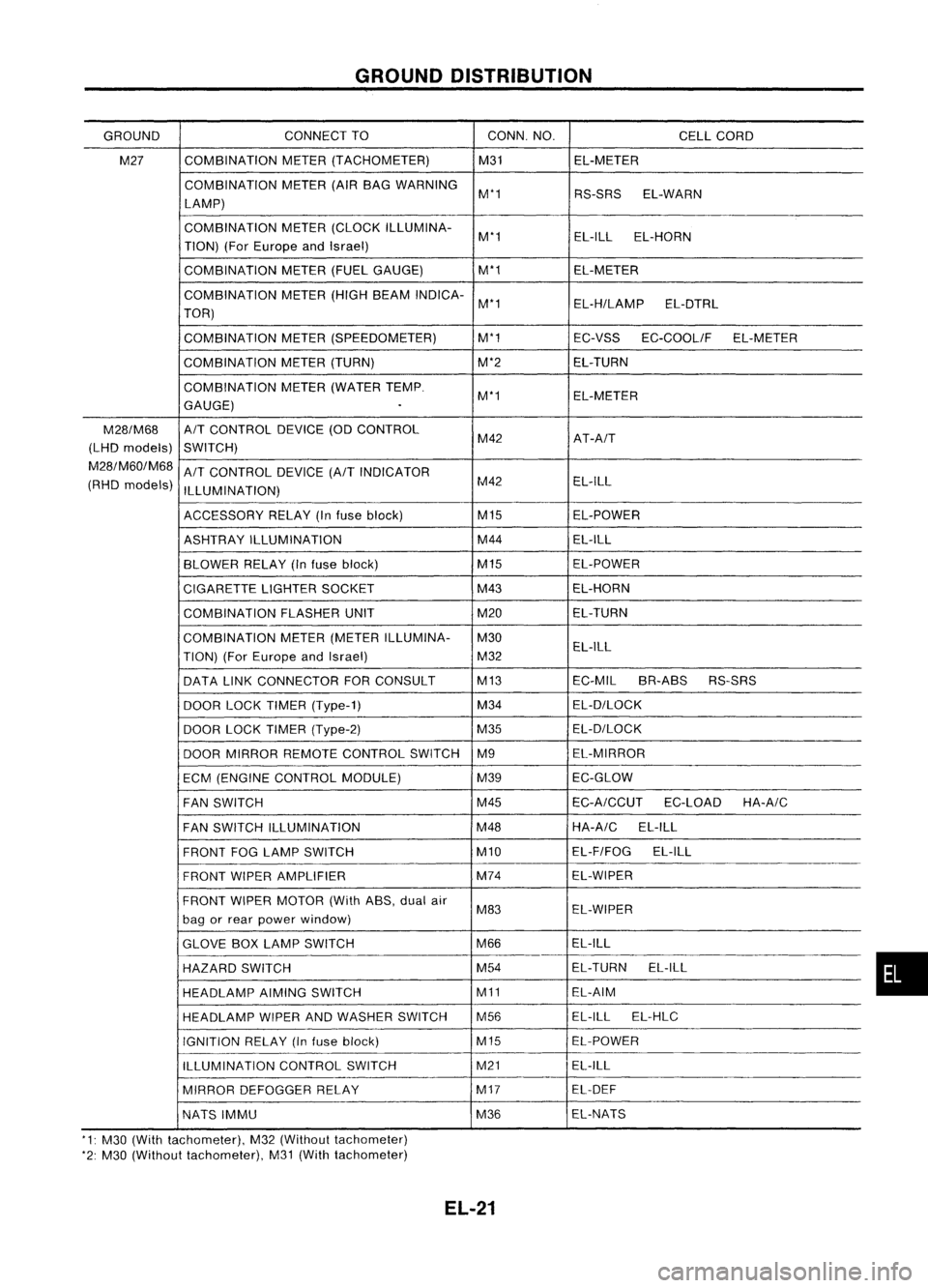
GROUNDDISTRIBUTION
GROUND CONNECT
TO CONN.NO.
CELLCORD
M27 COMBINATION
METER(TACHOMETER) M31EL-METER
COMBINATION METER(AIRBAG WARNING
M'1 RS-SRSEL-WARN
LAMP)
COMBINATION METER(CLOCK ILLUMINA-
M'1 EL-ILL
EL-HORN
TION) (ForEurope andIsrael)
COMBINATION METER(FUELGAUGE) M'1
EL-METER
COMBINATION METER(HIGHBEAM INDICA-
M'1 EL-H/LAMPEL-DTRL
TOR)
COMBINATION METER(SPEEDOMETER) M'1
EC-VSSEC-COOLIF EL-METER
COMBINATION METER(TURN) M'2EL-TURN
COMBINATION METER(WATER TEMP.
M'1 EL-METER
GAUGE)
.
M28/M68
A/T
CONTROL DEVICE(ODCONTROL
(LHD models)
SWITCH) M42
AT-A/T
M28/M60/M68
A/T
CONTROL DEVICE
(A/T
INDICATOR
(RHD models)
ILLUMINATION) M42
EL-ILL
ACCESSORY RELAY(Infuse block) M15
EL-POWER
ASHTRAY ILLUMINATION M44
EL-ILL
BLOWER RELAY(Infuse block) M15
EL-POWER
CIGARETTE LIGHTERSOCKET M43
EL-HORN
COMBINATION FLASHERUNIT M20EL-TURN
COMBINATION METER(METER ILLUMINA- M30
TION) (ForEurope andIsrael) M32EL-ILL
DATA LINKCONNECTOR FORCONSULT M13
EC-MILBR-ABS RS-SRS
DOOR LOCKTIMER (Type-1) M34
EL-D/LOCK
DOOR LOCKTIMER (Type-2) M35EL-D/LOCK
DOOR MIRROR REMOTE CONTROL SWITCHM9 EL-MIRROR
ECM (ENGINE CONTROL MODULE) M39EC-GLOW
FAN SWITCH M45
EC-A/CCUT
EC-LOADHA-A/C
FAN SWITCH ILLUMINATION M48HA-A/C
EL-ILL
FRONT FOGLAMP SWITCH M10EL-F/FOG
EL-ILL
FRONT WIPERAMPLIFIER M74
EL-WIPER
FRONT WIPERMOTOR (WithASS,dualair
M83 EL-WIPER
bag orrear power window)
GLOVE BOXLAMP SWITCH M66EL-ILL
HAZARD SWITCH M54
EL-TURN
EL-ILL
HEADLAMP AIMINGSWITCH M11EL-AIM
HEADLAMP WIPERANDWASHER SWITCH M56 EL-ILL
EL-HLC
IGNITION RELAY(Infuse block) M15EL-POWER
ILLUMINATION CONTROLSWITCH M21
EL-ILL
MIRROR DEFOGGER RELAY M17
EL-DEF
NATS IMMU M36EL-NATS
'1: M30 (With tachometer), M32(Without tachometer)
'2: M30 (Without tachometer), M31(With tachometer)
EL-21
•
Page 447 of 1701

Bulbcover
SEL995K HEADLAMP
Bulb Replacement
The headlamp isasemi-sealed beamtypewhich usesa
replaceable halogenbulb.Thebulb canbereplaced fromthe
engine compartment sidewithout removing theheadlamp body.
• Grasp onlytheplastic basewhen handling thebulb. Never
touch theglass envelope.
1. Disconnect thebattery cable.
2. Disconnect theharness connector fromtheback sideofthe
bulb.
3. Turn thebulb retaining ringcounterclockwise until
it
is free
from theheadlamp reflector,andthen remove it.
4. Pull offthe rubber cap.
5. Remove theheadlamp bulbcarefully. Donot shake orrotate
the bulb when removing it.
6. Install inthe reverse orderofremoval.
CAUTION:
• Do not leave headlamp reflector withoutbulbforalong
period oftime. Dust,moisture, smoke,etc.entering head-
lamp bodymayaffect theperformance ofthe head lamp.
Remove headlamp bulbfrom thehead lamp reflector just
before areplacement bulbisinstalled.
Bulb Specifications
Item
Semi-sealed beam
High/Low Wattage
(W)
60/55
f>
to
3 21 0
~ nOD
o
SEL226PAiming
Adjustment
When performing headlamp aiming adjustment, useanaiming
machine, aimingwallscreen orheadlamp tester.Aimers
should beingood repair, calibrated andoperated inaccor-
dance withrespective operationmanuals.
If any aimer isnot available, aimingadjustment canbedone as
follows:
For details, refertothe regulations inyour owncountry.
CAUTION:
• Keep alltires inflated tocorrect pressures.
• Place vehicle andtester onone and same flatsurface.
• See thatvehicle isunloaded (exceptforfull levels of
coolant, engineoiland fuel, andspare tire,jack andtools).
Have thedriver orequivalent weightplaced indriver's seat.
CAUTION: •
Be sure aiming switchisset to
"0"
when performing aiming
adjustment onvehicles equipped withheadlamp aiming con-
trol.
EL-75
Page 473 of 1701

GEL001EXTERIOR
LAMP
Front FogLamp BulbReplacement
The front foglamp isasemi-sealed beamtypewhich usesa
replaceable halogenbulb.
• Grasp onlytheplastic basewhen handling thebulb. Never
touch theglass envelope.
1. Disconnect thebattery cable.
2. Disconnect theharness connector fromtheback sideofthe
bulb.
3. Turn thebulb retaining ringcounterclockwise untilitis free
from thefront foglamp reflector, andthen remove it.
4. Pull offthe rubber cap.
5. Remove thefront foglamp bulbcarefully. Donot shake or
rotate thebulb when removing it.
6. Install inthe reverse orderofremoval.
CAUTION:
.' Donot leave frontfoglamp reflector withoutbulbforalong
period oftime. Dust, moisture, smoke,etc.entering frontfog
lamp bodymayaffect theperformance ofthe front foglamp.
Remove frontfoglamp bulbfrom thefront foglamp reflec-
tor just before areplacement bulbisinstalled.
Front FogLamp Aiming Adjustment
Before performing aimingadjustment, makesureofthe follow-
ing.
a. Keep alltires inflated tocorrect pressure.
b. Place vehicle onlevel ground.
c. See thatvehicle isunloaded (exceptforfull levels of
coolant, engineoiland fuel, andspare tire,jack, andtools).
Have thedriver orequivalent weightplaced indriver's seat.
Adjust aiming byturning theadjusting screw.
EL-101
•
Page 487 of 1701

INTERIORLAMP
ilium ination/Schematic
DL
COMPACT
DISKDECK ILLUMINATION
FAN
SWITCH ILLUMINATION
HEADLAMP WIPERANDWASHER SWITCH
ILLUMINA TION
HAZARD SWITCH ILLUMINATION
EI
REAR FOGLAMP SWITCH
ILLUMINA TION
rl
Q)
ro
Q)
L
E
(J)
.rl
H
Q)
+J
E
>
L
D
.rl
ro
Q)
Q)
C
+J
D
+J
ra ra
>
Q)
L
ra
+J
E
(J)
Q)
D
::J
0
H
Q
0
.c
0
.c .c
U
D
L
+J
+J
m
c
::J
.rl
.rl
+J
ro
lLJ
3E
3E
Q) Q)
.c
(J)
Q)
L
(J)+J (J)+J
e
+J
..-;
Q
0
r-l(/)
r-1(J)
W
.rl
Q)
0
'<-
OJ> OJ>
-!
3
D
L
D(J)
D(J)
0
::J
+J
0
0
+J(J)
E
lLJ
Q
E+J E+J
Q..-;
OJ .c
.c
OJ OJ
0
L
UOOlOOlU
D
I
0
X
I.r-l
I-rl
X
0
a:
LL
lLJ
---1.---1
---1.---1
W
L:
@@@)~
e
~@
II
GLOVE BOXLAMP GLOVEBOX
LAMP SWITCH
REAR WINDOW DEFOGGER SWITCH
ILLUMINA TION
CLOCK
•
ILLUMINA
TION
ILLUMINATION
CONTROL SWITCH
METER
FRONT FOGLAMP SWITCH
ILLUMINATION
EE
lLJ
L:
Hf-
I-If-
>-cc:JH
«HZ
O-!~
RADIO
ILLUMINATION
METER
lLJ
UJ
~
LL AIT
INDICATOR ILLUMINATION
ASHTRAY
ILLUMINATION
COMBINATION METER
I
I-
U
Z Ilf-
Occ:JL:H
a:O«3:
LLLL-!UJ
lLJ
UJ
~
LL
>-
a:
lLJ
f-
f-
«
m
I
U
f-
H
3:
UJ
Z
ZO
o
HL
f-O
H
ZU
cc:JU
H«
HEL060
EL-115