gas type NISSAN ALMERA N15 1995 Service Manual
[x] Cancel search | Manufacturer: NISSAN, Model Year: 1995, Model line: ALMERA N15, Model: NISSAN ALMERA N15 1995Pages: 1701, PDF Size: 82.27 MB
Page 191 of 1701

__________ PRECAUTIONS ___________
BODYALIGNMENT _
Precautions ForHandling HighStregth Steel Engine
Compartment
__ MEASURMENT POINTS__
Unit:mm
Front side
SBT088
Traction direction: ...
Not
recommended
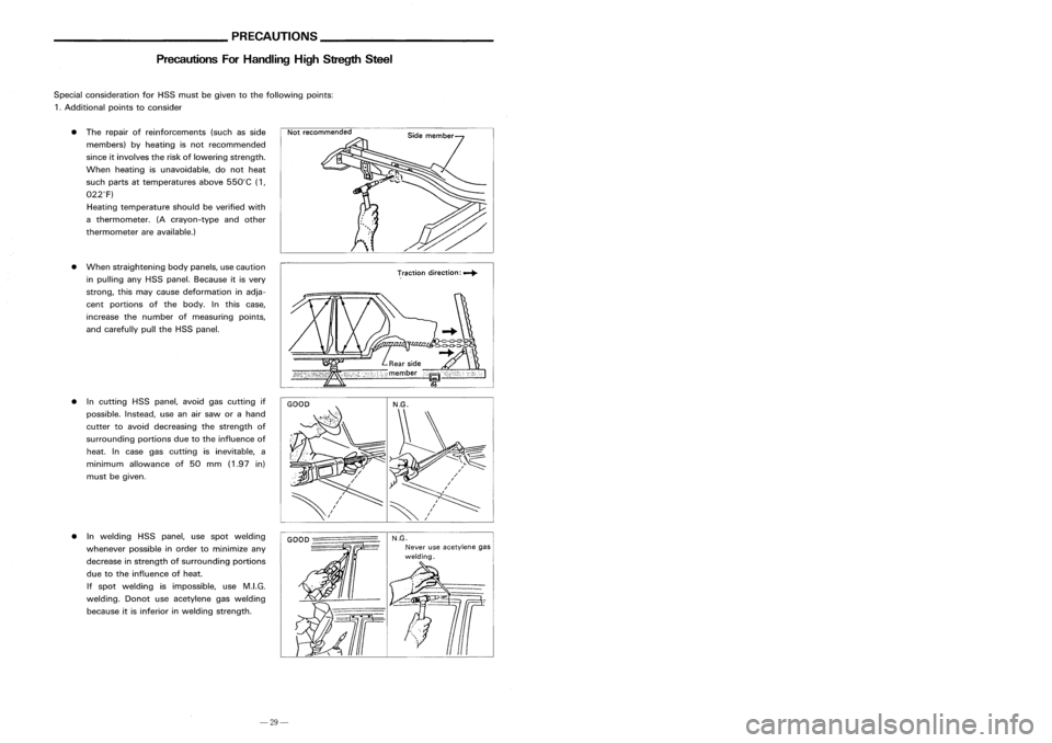
• The repair ofreinforcements (suchasside
members) byheating isnot recommended
since itinvolves theriskoflowering strength.
When heating isunavoidable, donot heat
such parts attemperatures above550°C (1,
022°F)
Heating temperature shouldbeverified with
a thermometer. (Acrayon-type andother
thermometer areavailable.)
• When straightening bodypanels, usecaution
in pulling anyHSS panel. Because itis very
strong, thismay cause deformation inadja-
cent portions ofthe body. Inthis case,
increase thenumber ofmeasuring points,
and carefully pulltheHSS panel.
Special
consideration forHSS must begiven tothe following points:
1 .Additional pointstoconsider
• Incutting HSSpanel, avoidgascutting if
possible. Instead,useanairsaw orahand
cutter toavoid decreasing thestrength of
surrounding portionsduetothe influence of
heat. Incase gascutting isinevitable, a
minimum allowance of50 mm (1.97 in)
must begiven.
SBT090
Radiator
coresupport lower
•
(b)
11
dia.
SBT094
• Inwelding HSSpanel, usespot welding
whenever possibleinorder tominimize any
decrease instrength ofsurrounding portions
due tothe influence ofheat.
If spot welding isimpossible, useM.LG.
welding. Donotuseacetylene gaswelding
because itis inferior inwelding strength.
GOOD
-================
N.G.
Never useacetylene .gas
welding.
Radiator
coresupport uppercenter
SBT091
-29-
-16-
Page 204 of 1701
__________ PRECAUTIONS ___________
BODYALIGNMENT _
Precautions ForHandling HighStregth Steel Engine
Compartment
__ MEASURMENT POINTS__
Unit:mm
Front side
SBT088
Traction direction: ...
Not
recommended
• The repair ofreinforcements (suchasside
members) byheating isnot recommended
since itinvolves theriskoflowering strength.
When heating isunavoidable, donot heat
such parts attemperatures above550°C (1,
022°F)
Heating temperature shouldbeverified with
a thermometer. (Acrayon-type andother
thermometer areavailable.)
• When straightening bodypanels, usecaution
in pulling anyHSS panel. Because itis very
strong, thismay cause deformation inadja-
cent portions ofthe body. Inthis case,
increase thenumber ofmeasuring points,
and carefully pulltheHSS panel.
Special
consideration forHSS must begiven tothe following points:
1 .Additional pointstoconsider
• Incutting HSSpanel, avoidgascutting if
possible. Instead,useanairsaw orahand
cutter toavoid decreasing thestrength of
surrounding portionsduetothe influence of
heat. Incase gascutting isinevitable, a
minimum allowance of50 mm (1.97 in)
must begiven.
SBT090
Radiator
coresupport lower
•
(b)
11
dia.
SBT094
• Inwelding HSSpanel, usespot welding
whenever possibleinorder tominimize any
decrease instrength ofsurrounding portions
due tothe influence ofheat.
If spot welding isimpossible, useM.LG.
welding. Donotuseacetylene gaswelding
because itis inferior inwelding strength.
GOOD
-================
N.G.
Never useacetylene .gas
welding.
Radiator
coresupport uppercenter
SBT091
-29-
-16-
Page 274 of 1701
GG94310000or
commercial equivalent
SBR820BA
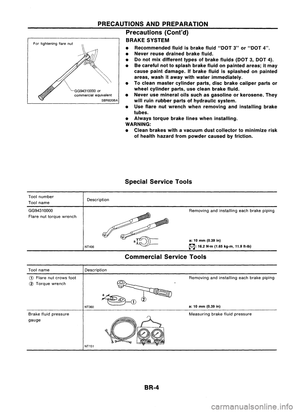
For
tightening flarenut
Tool number
Tool name
PRECAUTIONS
ANDPREPARATION
Precautions (Conl'd)
BRAKE SYSTEM
• Recommended fluidisbrake fluid"DOT 3"or"DOT 4".
• Never reusedrained brakefluid.
• Donot mix different typesofbrake fluids (DOT3,DOT 4).
• Becareful nottosplash brakefluidonpainted areas;itmay
cause paintdamage. Ifbrake fluidissplashed onpainted
areas, washitaway withwater immediately.
• Toclean master cylinder parts,discbrake caliper partsor
wheel cylinder parts,useclean brake fluid.
• Never usemineral oilssuch asgasoline orkerosene. They
will ruin rubber partsofhydraulic system.
• Use flare nutwrench whenremoving andinstalling brake
tubes.
• Always torquebrakelineswhen installing.
WARNING:
• Clean brakes withavacuum dustcollector tominimize risk
of health hazard frompowder causedbyfriction.
Special Service Tools
Description
GG9431 0000
Flare nuttorque wrench
NT406
Removing
andinstalling eachbrake piping
a: 10 mm (0.39 in)
~: 16.2N'm(1.65 kg-m, 11.9f1-lb)
Commercial ServiceTools
Description
Tool name
CD
Flare nutcrows foot
@ Torque wrench
Brake fluidpressure
gauge
NT360
NT151
Removing
andinstalling eachbrake piping
a: 10 mm (0.39 in)
Measuring brakefluidpressure
BR-4
Page 392 of 1701
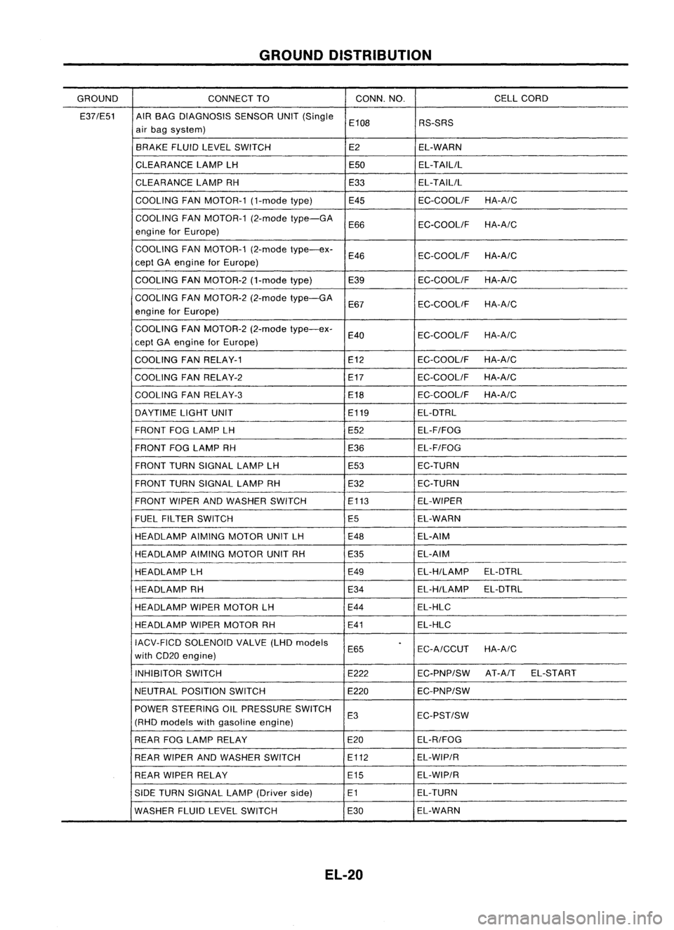
GROUNDDISTRIBUTION
GROUND CONNECTTO CONN.
NO. CELLCORD
E37/E51 AIRBAG DIAGNOSIS SENSORUNIT(Single
E108 RS-SRS
air bag system)
BRAKE FLUIDLEVEL SWITCH E2EL-WARN
CLEARANCE LAMPLH E50EL-TAILIL
CLEARANCE LAMPRH E33EL-TAILIL
COOLING FANMOTOR-1 (1-modetype) E45 EC-COOLIFHA-A/C
COOLING FANMOTOR-1 (2-modetype-GA
E66 EC-COOLIF
HA-A/C
engine forEurope)
COOLING FANMOTOR-1 (2-modetype-ex-
E46 EC-COOLIF
HA-A/C
eept GAengine forEurope)
COOLING FANMOTOR-2 (1-modetype)
E39 EC-COOLIFHA-A/C
-
COOLING FANMOTOR-2 (2-modetype-GA
E67 EC-COOLiF
HA-A/C
engine forEurope)
COOLING FANMOTOR-2 (2-modetype-ex-
E40 EC-COOLIFHA-A/C
eept GAengine forEurope)
COOLING FANRELAY-1 E12
EC-COOLIFHA-A/C
COOLING FANRELAY-2 E17
EC-COOLIFHA-A/C
COOLING FANRELAY-3 E18EC-COOLIF
HA-A/C
DAYTIME LIGHTUNIT E119EL-DTRL
FRONT FOGLAMP LH E52EL-F/FOG
FRONT FOGLAMP RH
E36EL-F/FOG
FRONT TURNSIGNAL LAMPLH E53EC-TURN
FRONT TURNSIGNAL LAMPRH E32EC-TURN
FRONT WIPERANDWASHER SWITCH E113
EL-WIPER
FUEL FILTER SWITCH
E5EL-WARN
HEADLAMP AIMINGMOTOR UNITLH E48
EL-AIM
HEADLAMP AIMINGMOTOR UNITRH E35 EL-AIM
HEADLAMP LH E49EL-H/LAMP
EL-DTRL
HEADLAMP RH E34EL-H/LAMP
EL-DTRL
HEADLAMP WIPERMOTOR LH E44
EL-HLC
HEADLAMP WIPERMOTOR RH E41EL-HLC
IACV-FICD SOLENOID VALVE(LHDmodels
.
E65 EC-A/CCUTHA-A/C
with CD20 engine)
INHIBITOR SWITCH E222EC-PNP/SWAT-A
IT EL-START
NEUTRAL POSITION SWITCH E220EC-PNP/SW
POWER STEERING OILPRESSURE SWITCH
E3 EC-PST/SW
(RHO models withgasoline engine)
REAR FOGLAMP RELAY E20EL-R/FOG
REAR WIPER ANDWASHER SWITCH E112EL-WIP/R
REAR WIPER RELAY E15EL-WIP/R
SIDE TURN SIGNAL LAMP(Driver side) E1 EL-TURN
WASHER FLUIDLEVEL SWITCH E30EL-WARN
EL-20
Page 523 of 1701

Ohmmeter- + WARNING
LAMPSANDBUZZER
Oil Pressure SwitchCheck
Oil pressure
Continuity
kPa (bar, kg/cm
2,
psi)
More than10-20
NO
Engine
start
(0.10-0.20, 0.1-0.2, 1.4-2.8)
Less than10-20
YES
Engine
stop
(0.10-0.20, 0.1-0.2, 1.4-2.8)
SEL748K
Test lamp 3.4WON
\ ,I
"
/
Ballery
Test lamp 3.4W OFF
~0
CD
Ballery
Gasoline MEL623D
SEL901F
Check
thecontinuity betweentheterminals ofoil pressure
switch andbody ground.
Fuel Warning LampSensor Check
• Itwill take ashort timeforthe bulb tolight.
Diode Check
• Check continuity usinganohmmeter.
• Diode isfunctioning properlyiftest results areasshown in
the figure atleft.
NOTE:
Specification mayvary depending onthe type oftester. Before
performing thisinspection, besure torefer tothe instruction
manual forthe tester tobe used.
• Diodes forwarning lampsarebuilt intothecombination
meter printed circuit.
Refer to"Combination Meter"(EL-127).
Warning BuzzerUnit
• Seat beltwarning lampiscontrolled bythe warning buzzer
unit.
Refer to"Warning Buzzer"(EL-152).
EL-151
•
Page 703 of 1701
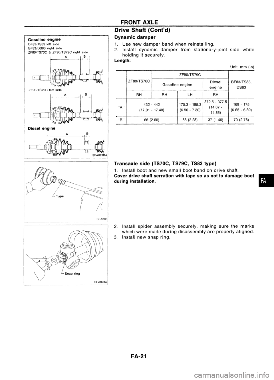
Gasolineengine
DF83/TS83 leftside
BF83/DS83 rightside
ZF80/TS70C
&
ZF90/TS79C rightside
A
B_1
.":JJ.Ci
ZF90/TS79C leftside
SFA800FRONT
AXLE
Drive Shaft(Cont'd)
Dynamic damper
1. Use new damper bandwhen reinstalling.
2. Install dynamic damperfromstationary-joint sidewhile
holding itsecurely.
Length:
Unit:mm(in)
ZF90/TS79C
ZF80/TS70C DieselBF83/TS83,
Gasoline engine
engineDS83
RH RH LHRH
372.5 -377.5
169-175
432 -442 175.3
-185.3
"A"
(17.01-17.40) (6.90
-7.30) (14.67
-
(6.65-6.89)
14.86)
"B"
66(2.60) 58(2.28) 37(1.46) 70(2.76)
Transaxle side(TS70C, TS79C,TS83type)
1. Install bootandnew small bootband ondrive shaft.
Cover driveshaftserration withtape soas not todamage boot•
during installation.
2. Install spider assembly securely.makingsurethemarks
which weremade during disassembly areproperly aligned.
3. Install newsnap ring.
FA-21
Page 722 of 1701
CONTENTS(Cont'd.)
TROUBLE DIAGNOSIS FORDTC
43 309
Throttle Position Sensor 309
TROUBLE DIAGNOSIS FORNON-DETECTABLE
ITEMS
314
Vehicle SpeedSensor (VSS) 314
Start Signal 317
Exhaust GasRecirculation (EGR)Valveand
EVAP Canister PurgeControl 319
Injector 324
Fuel Pump 327
Idle AirControl Valve(IACV)-Air Regulator 332
Idle AirControl Valve(IACV) -Auxiliary Air
Control (AAC)Valve :335
Idle AirControl Valve(IACV)-FICD Solenoid
Valve '"339
Cooling FanControl 343
Power Steering OilPressure Switch 354
Park/Neutral PositionSwitch 357
Heated Oxygen Sensor(H02S) 362
Torque
Converter
ClutchSolenoid Valve 367
Malfunction IndicatorLamp(MIL)
&
Data Link
Connector (DLC)forCONSULT 370
CD
INJECTION SYSTEM
371
VE.TYPE INJECTION PUMP
372
Removal 372
Installation 373
Adjustment 374
INJECTION NOZZLE
376
Removal andInstallation 376
Disassembly 376
Inspection 377
Cleaning 377
Assembly 378
Test andAdjustment 379
FUEL
SYSTEM CHECK
381
Priming PumpCheck 381
Fuel CutSolenoid Valve 381
CRANKCASE VENTILATION SYSTEM
382
Ventilation Hose 382
ENGINE ANDEMISSION CONTROLOVERALL
SYSTEM
383
Component PartsLocation 383
System Diagram 384
Circuit Diagram ,385
System Chart. 386
TROUBLE DIAGNOSES
387
ECM Terminals andReference Values 387
Quick-glow System 390
Partial LoadAdvance (PLA)Control 399
Cooling FanControl 404
Air Conditioner CutControl 413
Fuel CutControl 416
GA
SERVICE DATAANDSPECIFICATIONS
(505).417
General Specifications 417
Inspection andAdjustment.. 417
SR
SERVICE DATAANDSPECIFICATIONS
(505).418
General Specifications 418
Inspection andAdjustment.. .418
CD
SERVICE DATAANDSPECIFICATIONS
(505).419
VE-type Injection Pump 419
Injection Nozzle 419
•
When youread wiring diagrams:
• Read GIsection, "HOWTOREAD WIRING DIAGRAMS" .
• See Elsection, "POWER SUPPLYROUTING" forpower distribution circuit.
When youperform troublediagnoses, readGIsection, "HOWTOFOllOW FLOWCHART INTROU-
BLE DIAGNOSES" and"HOW TOPERFORM EFFICIENT DIAGNOSIS FORANELECTRICAL INCIDENT".
Page 1165 of 1701
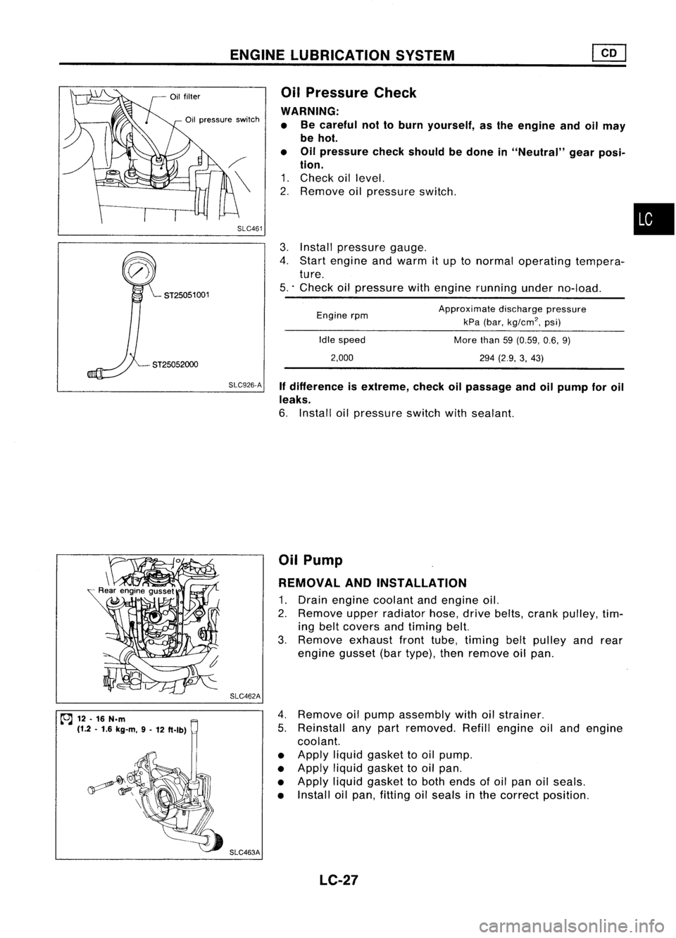
ENGINELUBRICATION SYSTEM
SLC926.A Ifdifference isextreme, checkoilpassage andoilpump foroil
leaks.
6. Install oilpressure switchwithsealant.
ST25052000
3.
Install pressure gauge.
4. Start engine andwarm itup tonormal operating tempera-
ture.
5 .. Check oilpressure withengine running underno-load.
•
Approximate dischargepressure
kPa (bar,
kg/cm
2,
psi)
More than59(0.59, 0.6,9)
294 (2.9, 3,43)
Idle
speed
2,000
Engine
rpm
Oil
Pressure Check
WARNING: • Becareful nottoburn yourself, asthe engine andoilmay
be hot.
• Oilpressure checkshould bedone in"Neutral" gearposi-
tion.
1. Check oillevel.
2. Remove oilpressure switch.
SLC461
Oil
pressure switch
ST25051 001
~ 12.16 N.m
(1.2 .1.6 kg-m, 9-
12 ft.lb) SLC462A
SLC463A Oil
Pump
REMOVAL ANDINSTAllATION
1. Drain engine coolant andengine oil.
2. Remove upperradiator hose,drivebelts, crank pulley, tim-
ing belt covers andtiming belt.
3. Remove exhaustfronttube, timing beltpulley andrear
engine gusset(bartype), thenremove oilpan.
4. Remove oilpump assembly withoilstrainer.
5. Reinstall anypart removed. Refillengine oiland engine
coolant.
• Apply liquidgasket tooil pump.
• Apply liquidgasket tooil pan.
• Apply liquidgasket toboth ends ofoil pan oilseals.
• Install oilpan, fitting oilseals inthe correct position.
LC-27
Page 1360 of 1701
PRECAUTIONS
Engine Oils(ConI' d)
• Wash withsoap andwater toensure alloil isremoved (skin
cleansers andnailbrushes willhelp). Preparations contain-
ing lanolin replace thenatural skinoilswhich havebeen
removed.
• Donot use gasoline, kerosine, dieselfuel,gasoil,thinners
or solvents forcleaning skin.
• If
skin disorders develop,obtainmedical advicewithout
delay.
• Where practicable, degreasecomponents priortohandling.
• Where thereisarisk ofeye contact, eyeprotection should
be worn, forexample, chemicalgogglesorface shields; in
addition aneye wash facility should beprovided.
ENVIRONMENTAL PROTECTIONPRECAUTIONS
Burning usedengine oilinsmall space heaters orboilers can
be recommended onlyforunits ofapproved design.Theheat-
ing system mustmeettherequirements ofHM Inspectorate of
Pollution forsmall burners ofless than 0.4MW. Ifin doubt check
with theappropriate localauthority and/ormanufacturer ofthe
approved appliance.
Dispose ofused oiland used oilfilters through authorized
waste disposal contractors tolicensed wastedisposal sites,or
to the waste oilreclamation trade.Ifin doubt, contact thelocal
authority foradvice ondisposal facilities.
It is illegal topour used oilontothe ground, downsewers or
drains, orinto water courses.
The regulations concerningthepollution ofthe environment
will vary between regions.
Precautions forFuel
GASOLINE ENGINE:
For Europe
Unleaded gasolineofat least 95octane (RON)
CAUTION: Do not use leaded gasoline. Usingleaded gasoline willdamage
the catalytic converter.
Except Europe
Unleaded gasolineofat least 91octane (RON)
DIESEL ENGINE*:
Diesel fuelofat least 50cetane
If two types ofdiesel fuelareavailable, usesummer or
winter fuelproperly according tothe following temperature
conditions.
• Above -rc(20°F) Summer typediesel fuel.
• Below
-rc
(20°F) Wintertypediesel fuel.
CAUTION:
• Donot use home heating oil,gasoline, orother alternate
fuels inyour diesel engine. Theuseofthose cancause
engine damage.
• Donot use summer fuelattemperature below_7°C(20°F).
The cold temperatures willcause waxtoform inthe fuel. As
a result, itmay prevent theengine fromrunning smoothly.
• Donot add gasoline orother alternate fuelstodiesel fuel.
GI-6
Page 1405 of 1701

PRECAUTIONSANDPREPARATION
Precautions forWorking withHFC-134a (R-134a)
WARNING:
• CFC-12 (R-12)refrigerant andHFC-134a (R-134a)refrigerant arenotcompatible. Theserefrigerants
must never bemixed, eveninthe smallest amounts. Ifthe refrigerants aremixed, compressor fail-
ure islikely tooccur .
• Use only specified lubricantforthe HFC-134a (R-134a)
A/C
system andHFC-134a (R-134a)compo-
nents. Iflubricant otherthanthatspecified isused, compressor failureislikely tooccur .
• The specified HFC-134a (R-134a)lubricant rapidlyabsorbs moisture fromtheatmosphere. Thefol-
lowing handling precautions mustbeobserved:
a: When removing refrigerant components fromavehicle, immediately cap(seal) thecomponent
to minimize theentry ofmoisture fromtheatmosphere.
b: When installing refrigerant components toavehicle, donot remove thecaps (unseal) untiljust
before connecting thecomponents. Connectallrefrigerant loopcomponents asquickly aspos-
sible tominimize theentry ofmoisture intosystem.
c: Only usethespecified lubricantfr.omasealed container. Immediately resealcontainers of
lubricant. Withoutpropersealing, lubricant willbecome moisture saturated andshould notbe
used.
d: Avoid breathing
A/C
refrigerant andlubricant vaporormist. Exposure mayirritate eyes,nose
and throat. Remove R-134afromthe
A/C
system, usingcertified serviceequipment meeting
requirements ofSAE J2210 (R-134a recycling eqUipment), orJ2209 (R-134a recovery equipment).
If accidental systemdischarge occurs,ventilate workareabefore resuming service.Additional
health andsafety information maybeobtained fromrefrigerant andlubricant manufacturers.
e: Do not allow lubricant (Nissan
A/C
System OilType S)tocome incontact withstyrofoam parts.
Damage mayresult.
GeneralRefrigerant Precautions
WARNING:
• Donot release refrigerant intotheair. Use approved recoverylrecycling equipmenttocapture the
refrigerant everytimeanair conditioning systemisdischarged.
• Always weareyeand hand protection (gogglesandgloves) whenworking withanyrefrigerant or
air conditioning system.
• Donot store orheat refrigerant containersabove52°C(125°F).
• Donot heat arefrigerant containerwithanopen flame; ifcontainer warmingisrequired, placethe
bottom ofthe container inawarm pailofwater.
• Donot intentionally drop,puncture, orincinerate refrigerant containers.
• Keep refrigerant awayfromopen flames: poisonous gaswillbeproduced ifrefrigerant burns.
• Refrigerant willdisplace oxygen,therefore becertain towork inwell ventilated areastoprevent
suffocation.
• Donot introduce compressed airtoany refrigerant containerorrefrigerant component.
HA-3
•