relay NISSAN ALMERA N15 1995 Service Manual
[x] Cancel search | Manufacturer: NISSAN, Model Year: 1995, Model line: ALMERA N15, Model: NISSAN ALMERA N15 1995Pages: 1701, PDF Size: 82.27 MB
Page 279 of 1701
CONTROLVALVE
Proportioning Valve
INSPECTION
CAUTION:
• Carefully monitorbrakefluidlevel atmaster cylinder.
• Use new brake fluid"DOT 3"or"DOT 4".
• Donot mix different typesofbrake fluids(DOT3,DOT 4).
• Becareful nottosplash brakefluidonpainted areas;itmay
cause paintdamage. Ifbrake fluidissplashed onpaint
areas, washitaway withwater immediately.
• Depress pedalslowly whenraising frontbrake pressure.
• Check rearbrake pressure 2seconds afterfront brake pres-
sure reaches specified value.
• For models withABS disconnect harnessconnectors from
ABS actuator relaybefore checking.
1.
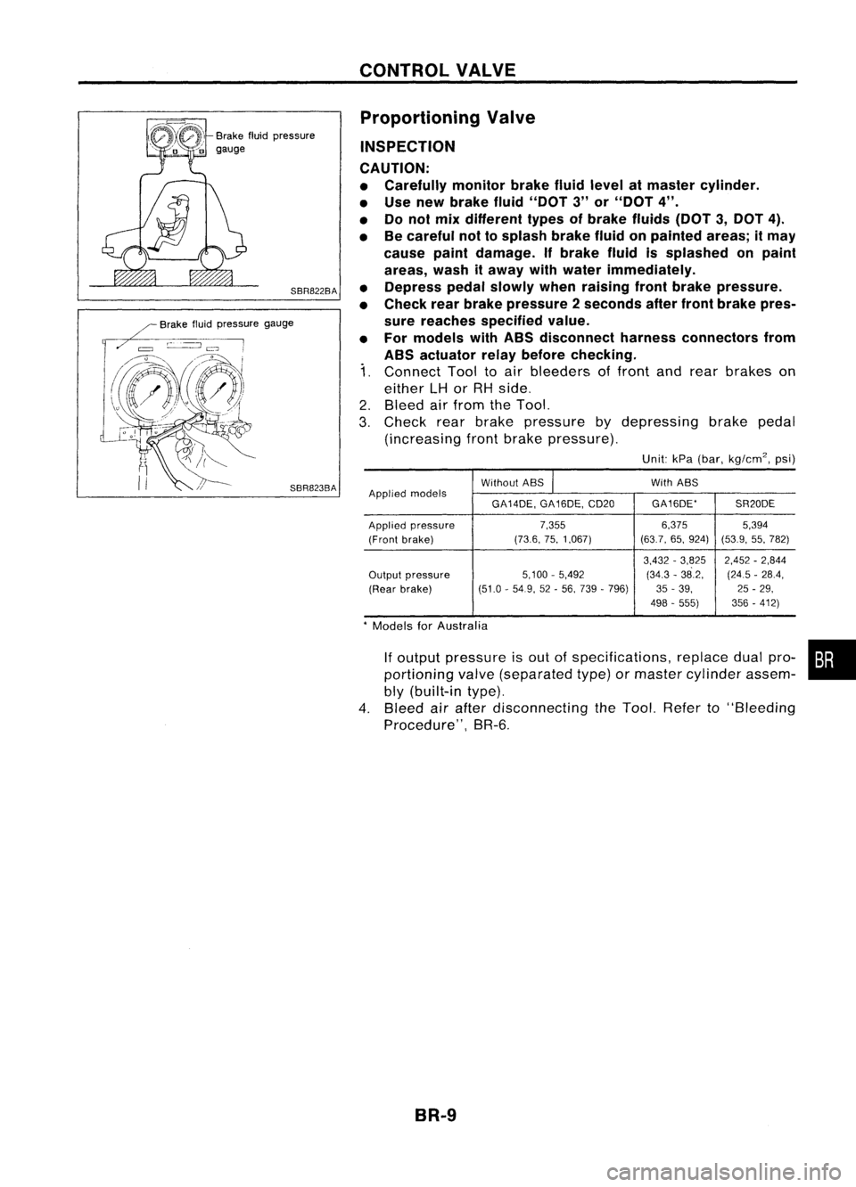
Connect Tooltoair bleeders offront andrear brakes on
either
LH
or
RH
side.
2. Bleed airfrom theTool.
3. Check rearbrake pressure bydepressing brakepedal
(increasing frontbrake pressure).
Unit:kPa(bar, kg/cm
2,
psi)
Without ABS
I
With
ABS
Applied models
GA14DE,GA16DE,CD20 GA16DE'
SR20DE
Applied pressure 7.3556.375
5,394
(Front brake) (73.6,
75,1,067) (63.7,65,924)
(53.9,55,782)
3,432 -3,825 2,452-2,844
Output pressure 5,100
-5,492 (34.3-38.2, (245-28.4,
(Rear brake) (51.0
-54.9, 52-56, 739 -796) 35-39, 25-29,
498 -555) 356-412)
*
Models forAustralia
If
output pressure isout ofspecifications, replacedualpro- •••
portioning valve(separated type)ormaster cylinder assem-
bly (built-in type).
4. Bleed airafter disconnecting theTool. Refer to"Bleeding
Procedure", BR-5.
BR-9
Page 309 of 1701

ANTI-LOCKBRAKESYSTEM
System Components
Dual proportioning
valve
Rearwheel sensors
For LHD models, controlunit
is located onthe opposite side.
SBR048DB
Control unit
s::';o~'~W.
r
I .I
Tooth~ Sensorrotor
/ ~m~f onetooth
v:~-- System
Description
SENSOR
The sensor unitconsists ofagear-shaped sensorrotoranda
sensor element. Theelement contains abar magnet around
which acoil iswound. Thesensor isinstalled onthe back side
of the brake rotor.Sine-wave currentisgenerated bythe sen-
sor asthe wheel rotates. Thefrequency andvoltage increase(s) •
as the rotating speedincreases. :•
V: Induced electromotive force
SBR124B
SBR049DA CONTROL
UNIT
The control unitcomputes thewheel rotating speedbythe sig-
nal current sentfrom thesensor. Thenitsupplies aDC current
to the actuator solenoid valve.Italso controls ON-OFFopera-
tion ofthe valve relayandmotor relay.Ifany electrical malfunc-
tion should bedetected inthe system, thecontrol unitcauses
the warning lamptolight up.Inthis condition, theASS willbe
deactivated bythe control unit,andthevehicle's brakesystem
reverts tonormal operation.
BR-39
Page 312 of 1701
,ryside
linder prima
From master cy ndaryside
r
der seco
master cyIn
From
RHO
cc:J
11-15 .11)
(1.1 .
1.5, 8
~ Front
LHO
ASS
relay
box
ground
Actuator
cable
---------~~~~~:A~K~EirS;V~S~T~EWo.M;(c:O;;~'diij)I----
ANTI-LOCK
BRdInstallation (Cont
Removal an
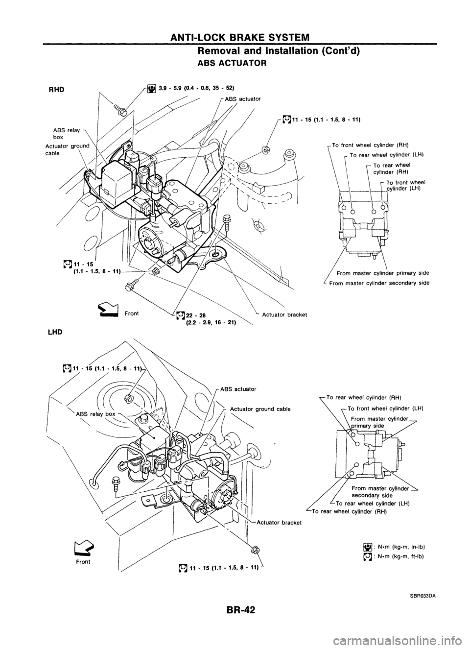
ABS ACTUATOR
heelcylinder (RH)
To rear
W
clinder (LH)
f ntwheel y
To ro
aster cylinder
From m
primary side
aster cylinder
From m 'de
secondary
Sl
(LH)
Wheel cylinder
To rear
W
heel cylinder (RH)
To
rear
(kg-m.in-Ib)
r.ii1
'N.m
IX! '
(kg-m. ft-Ib)
cc:J:
N.m
SBR033DA
BR-42
Page 313 of 1701

ANTI-LOCKBRAKESYSTEM
Removal andInstallation (Cont'd)
1. Disconnect batterycable.
2. Drain brake fluid.Refer toSR-5.
3. Discharge airconditioner refrigerant.RefertoHA section
("R-134a ServiceProcedure", "SERVICEPROCEDURES").
4. Disconnect allconnectors fromASSrelay bracket.
5. Remove mounting boltforrelay bracket.
6. Remove ASSrelay boxwith bracket.
7. Remove airconditioner low-pressure tubes.RefertoHA
section, ("Refrigerant Lines","SERVICE PROCEDURES") .
8. Disconnect brakepipesandmove awayfromactuator.
It is not necessary toremove thesepipesfromvehicle.
9. Remove/loosen mountingnutsbetween actuatorand
bracket.
BR-43
•
Page 314 of 1701

ANTI-LOCKBRAKESYSTEM
Removal andInstallation (Cont'd)
10. Draw outASS actuator asshown.
ASS
actuator
SBR039D CAUTION:
After installation, payattention tothe following points:
• Refill brake fluidandbleed air.Refer to"CHECK AND
ADJUSTMENT", BR-5and"AIR BLEEDING", BR.6,respec-
tively.
• Charge airconditioner refrigerant.RefertoHA section,
("R-134a ServiceProcedure", "SERVICEPROCEDURES").
• The installation procedureisthe reverse ofremoval.
ASS
actuator
_-=--=--=--=--_-_-\,_~
""'~t"
b"ok.,
SBR040D
ABSRELAYS
1. Disconnect batterycable.
2. Remove ASSrelay cover.
BR-44
Page 321 of 1701

ANTI-LOCKBRAKESYSTEM
Wiring Diagram -ABS -(ConI' d)
SR-ASS-07
I
BAT.ERY
I
rJ:~~30A
LtJw LtJm
Refer
to
EL-POWER. SOLENOID
VALVE
RELAY
CONTROL
(-)
1
3:
I
LG/R MOTOR
RELAY
MONITOR
~
L
MOTOR
RELAY
CONTROL
(+)
~
Y
MOTOR
RELAY
CONTROL
(-)
4=U
G/R
ABS
CONTROL
UNIT
~
BR Y
tt
J
t
.
Precedin
g{ ~
-
page
-
B
rg.~~, ~
L/B~
tttt
•
t
BR LIBLG/R
LY
Y G/R
ffi
n=fo]
rh
m
n=f3n
m
rrf1iJ
*
-----<
@>
@ @
@)
SOLENOID
I:
~
)
~
MOTOR
VALVE
I
?
RELAY
RELAY
(lli)
I@
@
@>
I@
~
ABS
RELAY •
BOX :.
UQ)
~)
~----------------------~
I
: UQ)
I
(411'3)
GY
I
~~
~B
Refer
tolast page
(Foldout page).
~----------------------~
BR-51
HBRDDa
Page 322 of 1701
TROUBLEDIAGNOSES
Contents
How toPerform TroubleDiagnoses forQuick andAccurate Repair SR-52
Self-diagnosis SR-53
CONSULT BR-58
CONSULT Inspection Procedure BR-59
Component PartsandHarness Connector Location BR-64
Preliminary Check BR-65
Ground CircuitCheck BR-66
Circuit Diagram forQuick Pinpoint Check BR-67
Diagnostic Procedure1Warning lampdoes notcome on BR-68
Diagnostic Procedure2Warning lampstays on BR-69
Diagnostic Procedure3ABS actuator solenoid valve BR-72
Diagnostic Procedure 4Wheel sensor orrotor BR-74
Diagnostic Procedure5Motor relayormotor BR-76
Diagnostic Procedure6Solenoid valverelay BR-79
Diagnostic Procedure7Power supply BR-81
Diagnostic Procedure 8Control unit BR-82
Diagnostic Procedure9Pedal vibration andnoise BR-82
Diagnostic Procedure10Long stopping distance BR-83
Diagnostic Procedure11Unexpected pedalaction BR-83
Diagnostic Procedure12ABS does notwork BR-84
Diagnostic Procedure13ABS works frequently BR-84
Electrical Component Inspection BR-85
How toPerform TroubleDiagnoses forQuick
and Accurate Repair
INTRODUCTION
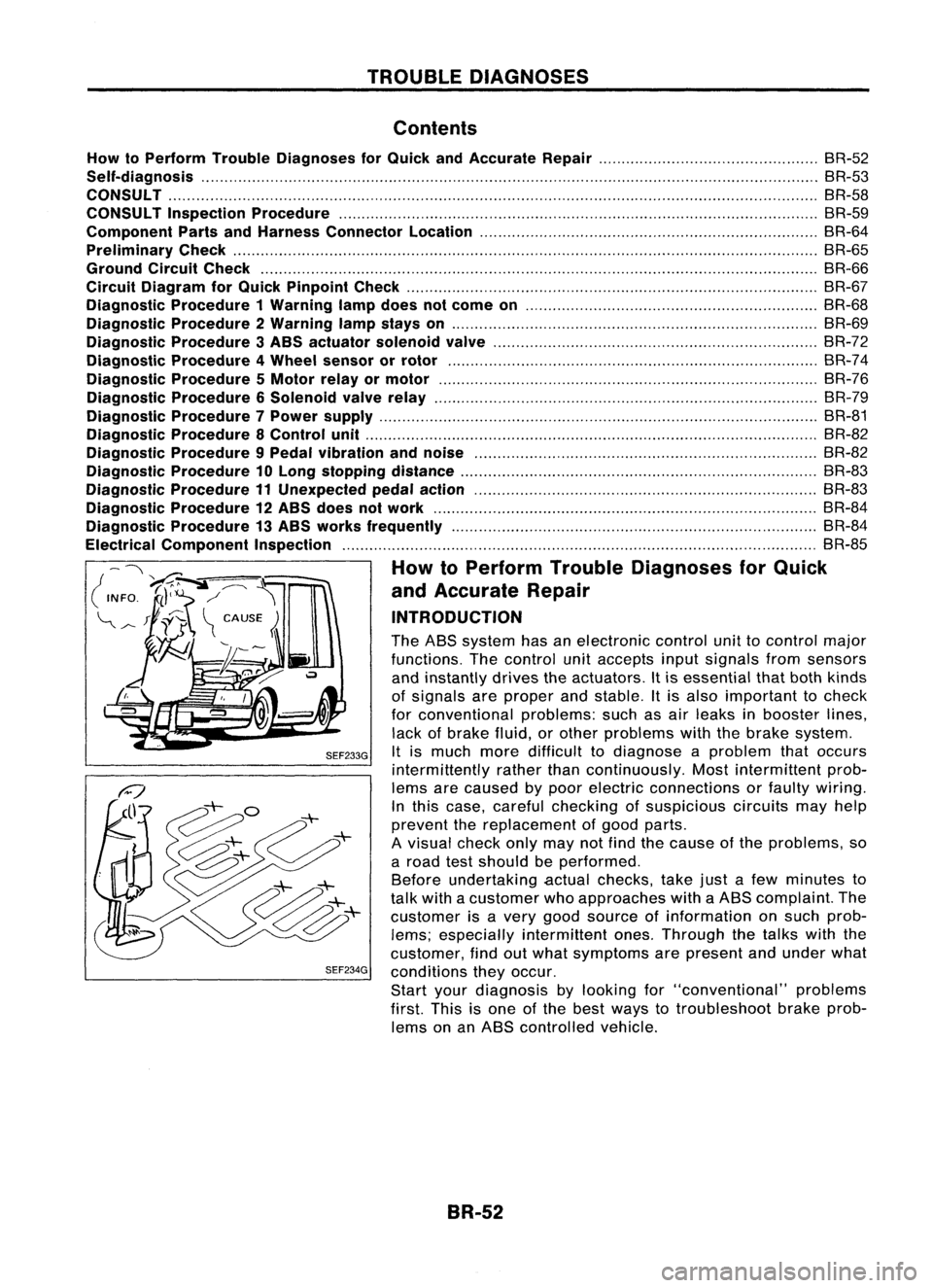
The ABS system hasanelectronic controlunittocontrol major
functions. Thecontrol unitaccepts inputsignals fromsensors
and instantly drivestheactuators. Itis essential thatboth kinds
of signals areproper andstable. Itis also important tocheck
for conventional problems:suchasair leaks inbooster lines,
lack ofbrake fluid,orother problems withthebrake system.
SEF233G
Itis much moredifficult todiagnose aproblem thatoccurs
intermittently ratherthancontinuously. Mostintermittent prob-
lems arecaused bypoor electric connections orfaulty wiring.
In this case, careful checking ofsuspicious circuitsmayhelp
prevent thereplacement ofgood parts.
A visual checkonlymaynotfind thecause ofthe problems, so
a road testshould beperformed.
Before undertaking actualchecks, takejustafew minutes to
talk with acustomer whoapproaches withaABS complaint. The
customer isavery good source ofinformation onsuch prob-
lems; especially intermittent ones.Through thetalks withthe
customer, findoutwhat symptoms arepresent andunder what
SEF234G
conditions theyoccur.
Start yourdiagnosis bylooking for"conventional" problems
first. Thisisone ofthe best ways totroubleshoot brakeprob-
lems onanABS controlled vehicle.
BR-52
Page 325 of 1701

TROUBLEDIAGNOSES
Self-diagnosis (ForEurope) (Cont'd)
MALFUNCTION CODE/SYMPTOM CHART
Code No.
Malfunctioningpart Diagnostic
procedure
(No. ofwarning lampflashes)
45
Actuator
frontleftoutlet solenoid valve
3
46
Actuator
frontleftinlet solenoid valve
3
41
Actuator
frontrightoutlet solenoid valve
3
42
Actuator
frontrightinletsolenoid valve
3
51
Actuator
rearright outlet solenoid valve
3
52
Actuatorrearright inletsolenoid valve
3
55
Actuator
rearleftoutlet solenoid valve
3
56
Actuator
rearleftinlet solenoid valve
3
25
Frontleftsensor (open-circuit)
4
26
Front
leftsensor (short-circuit)
4
21
Frontrightsensor (open-circuit)
4
22
Front
rightsensor (short-circuit)
4
35
Rearleftsensor (open-circuit)
4
36
Rear
leftsensor (short-circuit)
4
31
Rearrightsensor (open-circuit)
4
32
Rearrightsensor (short-circuit)
4
18
Sensorrotor
4
61
Actuatormotorormotor relay
5
63
Solenoidvalverelay
6
57
Powersupply (Lowvoltage)
7
71
Controlunit
8
Control unitpower supply circuit
Warning lampstays onwhen igni-Warning
lampbulbcircuit
tion switch isturned on Control
unitorcontrol unitconnector
2
Solenoid valverelaystuck
Power supply forsolenoid valverelaycoil
Warning lampstays on,during
Controlunit
-
self-diagnosis
Warning lampdoesnotcome onFuse, warning lampbulborwarning lampcircuit
1
when ignition switchisturned onControl unit
Warning lampdoes notcome on
Control unit
during self-diagnosis
-
Pedal vibration andnoise
-
9
Long stopping distance
-
10
Unexpected pedalaction
-
11
ABS does notwork
-
12
ABS works frequently
-
13
BR-55
•
Page 328 of 1701

TROUBLEDIAGNOSES
CONSULT
CONSULT APPLICATION TOASS
ITEM SELF-DIAGNOSTIC
DATAMONITOR ACTIVETEST
RESULTS
Front rightwheel sensor
XX
-
Front leftwheel sensor
XX
-
Rear rightwheel sensor
XX
-
Rear leftwheel sensor
XX
-
Stop lamp switch
-
X
-
Front rightinletsolenoid valve
XXX
Front rightoutlet solenoid valve
X
XX
Front leftinlet solenoid valve
XXX
Front leftoutlet solenoid valve
XX
X
Rear rightinletsolenoid valve
XX
X
Rear leftinlet solenoid valve
XXX
Rear rightoutlet solenoid valve
X
XX
Rear leftoutlet solenoid valve
X
X
.X
Actuator solenoid valverelay
XX
-
Actuator motorrelay
(ABS MOTOR isshown onthe Data Monitor
X
XX
screen.)
ABS warning lamp
-
X
-
Battery voltage
XX
-
X: Applicable
-; Not applicable
ECU partnumber mode
Ignore theECU partnumber displayed inthe ECU PART NUMBER MODE.Refertoparts catalog toorder
the ECU.
BR-58
Page 330 of 1701

TROUBLEDIAGNOSES
CONSULT Inspection Procedure(Conl'd)
SELF-DIAGNOSTIC RESULTSMODE
Diagnostic item
Diagnosticitemisdetected when... Diagnostic
procedure
FR RH SENSOR
•Circuit forfront rightwheel sensor isopen.
4
[OPEN] (Anabnormally highinput voltage isentered.)
FR LH SENSOR
•Circuit forfront leftwheel sensor isopen.
4
[OPEN] (Anabnormally highinput voltage isentered.)
RR RHSENSOR
•Circuit forrear right sensor isopen.
4
[OPEN] (Anabnormally highinput voltage isentered.)
RR LHSENSOR
•Circuit forrear leftsensor isopen.
4
[OPEN] (Anabnormally highinput voltage isentered.)
FR RH SENSOR
•Circuit forfront rightwheel sensor isshorted.
4
[SHORT] (Anabnormally lowinput voltage isentered.)
FR LH SENSOR
•Circuit forfront leftwheel sensor isshorted.
4
[SHORT] (Anabnormally lowinput voltage isentered.)
RR RH SENSOR
•Circuit forrear right sensor isshorted.
4
[SHORT] (Anabnormally lowinput voltage isentered.)
RR LHSENSOR
•Circuit forrear leftsensor isshorted.
4
[SHORT] (Anabnormally lowinput voltage isentered.)
ABS SENSOR
•Teeth damage onsensor rotororimproper installation ofwheel sensor.
4
[ABNORMAL SIGNAL]
(Abnormalwheelsensor signalisentered.)
FR RH INABS SOL
•Circuit forfront rightinletsolenoid valveisopen.
3
[OPEN] (Anabnormally lowoutput voltage isentered.)
FR LH INABS SOL
•Circuit forfront leftinlet solenoid valveisopen.
3
[OPEN] (Anabnormally lowoutput voltage isentered.)
RR RH INABS SOL
•Circuit forrear right inletsolenoid valveisopen.
3
[OPEN] (Anabnormally lowoutput voltage isentered.)
RR LHINABS SOL
•Circuit forrear leftinlet solenoid valveisopen.
3
[OPEN] (Anabnormally lowoutput voltage isentered.)
FR RH INABS SOL
•Circuit forfront rightinletsolenoid valveisshorted.
3
[SHORT] (Anabnormally highoutput voltage isentered.)
FR LH INABS SOL
•Circuit forfront leftinlet solenoid valveisshorted.
3
[SHORT] (Anabnormally highoutput voltage isentered.)
RR RH INABS SOL
•Circuit forrear right inletsolenoid valveisshorted.
3
[SHORT] (Anabnormally highoutput voltage isentered.)
RR LHINASS SOL
•Circuit forrear leftinlet solenoid valveisshorted.
3
[SHORT] (Anabnormally highoutput voltage isentered.)
FR RH OUT ABSSOL
•Circuit forfront rightoutlet solenoid valveisopen.
3
[OPEN] (Anabnormally lowoutput voltage isentered.)
FR LH OUT ASS SOL
•Circuit forfront leftoutlet solenoid valveisopen.
3
[OPEN] (Anabnormally lowoutput voltage isentered.)
RR RH OUT ASSSOL
•Circuit forrear right outlet solenoid valveisopen.
3
[OPEN] (Anabnormally lowoutput voltage isentered.)
RR LHOUT ABSSOL
•Circuit forrear leftoutlet solenoid valveis.open.
3
[OPEN] (Anabnormally lowoutput voltage isentered.)
FR RH OUT ASSSOL
•Circuit forfront rightoutlet solenoid valveisshorted.
3
[SHORT] (Anabnormally highoutput voltage isentered.)
FR LH OUT ABSSOL •Circuit forfront leftoutlet solenoid valveisshorted.
3
[SHORT] (Anabnormally highoutput voltage isentered.)
RR RHOUT ABSSOL •Circuit forrear right outlet solenoid valveisshorted.
3
[SHORT] (Anabnormally highoutput voltage isentered.)
RR LHOUT ASSSOL •Circuit forrear leftoutlet solenoid valveisshorted.
3
[SHORT] (Anabnormally highoutput voltage isentered.)
ABS ACTUATOR RELAY
•Actuator solenoid valverelayisON, even control unitsends offsignal.
6
[FAILURE] •Actuator solenoid valverelayisOFF, even control unitsends onsignal.
ABS MOTOR
•Circuit foractuator motorisopen orshorted.
5
[FAILURE] •Actuator motorrelayisstuck.
BATTERY VOLT
•Power source voltage supplied toABS control unitisabnormally low. 7
[VB-LOW]
CONTROL UNIT •Function ofcalculation inASS control unithasfailed.
8
BR-50