jump start NISSAN ALMERA N15 1995 Service Manual
[x] Cancel search | Manufacturer: NISSAN, Model Year: 1995, Model line: ALMERA N15, Model: NISSAN ALMERA N15 1995Pages: 1701, PDF Size: 82.27 MB
Page 397 of 1701

SEL711EBATTERY
CAUTION:
• If
itbecomes necessary tostart theengine withabooster
battery andjumper cables, usea12-volt booster battery.
• After connecting batterycables, ensurethatthey aretightly
clamped tobattery terminals forgood contact.
• Never adddistilled waterthrough thehole used tocheck
specific gravity.
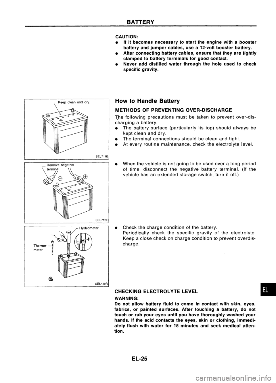
How toHandle Battery
METHODS OFPREVENTING OVER-DISCHARGE
T.he following precautions mustbetaken toprevent over-dis-
charging abattery.
• The battery surface (particularly itstop) should always be
kept clean anddry.
• The terminal connections shouldbeclean andtight.
• Atevery routine maintenance, checktheelectrolyte level.
SEL459R
•
When thevehicle isnot going tobe used overalong period
of time, disconnect thenegative batteryterminal. (Ifthe
vehicle hasanextended storageswitch,turnitoff.)
• Check thecharge condition ofthe battery.
Periodically checkthespecific gravityofthe electrolyte.
Keep aclose check oncharge condition toprevent overdis-
charge.
CHECKING ELECTROLVTELEVEL •
WARNING: Do not allow battery fluidtocome incontact withskin, eyes,
fabrics, orpainted surfaces. Aftertouching abattery, donot
touch orrub your eyes untilyouhave thoroughly washedyour
hands. Ifthe acid contacts theeyes, skinorclothing, immedi-
ately flush withwater for15minutes andseek medical atten-
tion.
EL-25
Page 760 of 1701

•
oxygen
sen-
Europe and
nd Australia
els)
sensor
for Europe
el, and Aus-
T models)
@
II
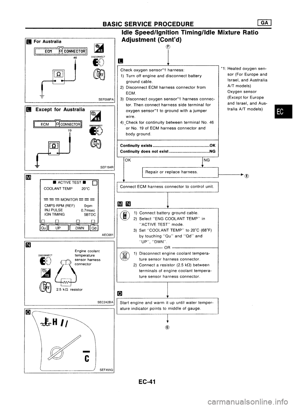
Check oxygen sensor*1 harness: *1:
Heated
1) Turn offengine anddisconnect battery sor
(For
ground cable. Israel,
a
2) Disconnect ECMharness connector from
AIT
mod
ECM. Oxygen
3) Disconnect oxygensensor*1 harnessconnec- (Except
tor. Then connect harness sideterminal for and
Isra
oxygen sensor*1 toground withajumper tralia
AI
wire.
4) .Check forcontinuity betweenterminalNo.46
or No. 19ofECM harness connector and
body ground.
Continuity exists................................................ OK
Continuity doesnotexist .................................. NG
OK lNG
I
Repair orreplace harness.
Connect ECMharness connector tocontrol unit.
~
III
00
1)
Connect batteryground cable.
2) Select "ENGCOOLANT TEMP"in
"ACTIVE TEST"mode.
3) Set "COOLANT TEMP"to20°C (68°F)
by touching "au"and"ad" and
"UP", "DWN".
OR
@
1)
Disconnect enginecoolant tempera-
ture sensor harness connector.
2) Connect aresistor (2.5kQ)between
terminals ofengine coolant tempera-
ture sensor harness connector.
[+]
Start engine andwarm itup until water temper-
ature indicator pointstomiddle ofgauge.
~
BASIC
SERVICE PROCEDURE ~
Idle Speed/Ignition Timing/IdleMixtureRatio
Adjustment (Cont'd)
CD
SEF194R
SEF056PA
~
DISCONNECT
18
~
AEC681
===MONITOR===
CMPS.RPM (REF)
Orpm
INJ PULSE
O.7msec
IGN TIMING 5BTDC
SEC242BA
•
ACTIVE TEST.
0
COOLANT TEMP 20°C
Engine coolant
DISCONNECT
temperature
10
!;j:~:~~'~";"'"
~
00
2.5k
n
resistor
II
ECM
19'
CONNECTOR
II
19
II
For Australia
II
ECM ~CONNECTORII
46
II
Except forAustralia
SEF455Q EC-41
Page 921 of 1701

TROUBLEDIAGNOSIS FORNON-DETECTABLE ITEMS
Valve Timing Control (VTC)(Cant'd)
DIAGNOSTIC PROCEDURE
INSPECTION START
m
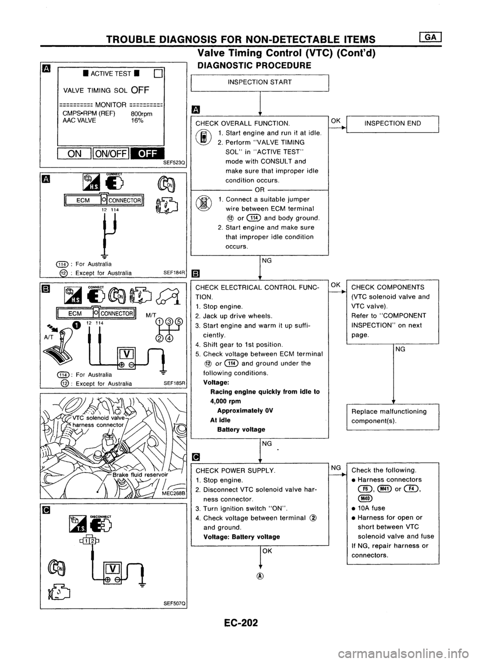
CHECK OVERALL FUNCTION.
~
INSPECTION
END
00
1.
Start engine andrunitat idle.
2. Perform "VALVETIMING
SOL" in"ACTIVE TEST"
mode withCONSULT and
make surethatimproper idle
condition occurs.
OR
00
1.
Connect asuitable jumper
wire between ECMterminal
@
or
@
andbody ground.
2. Start engine andmake sure
that improper idlecondition
occurs.
NG
iii
CHECK ELECTRICAL CONTROLFUNC-OK
CHECK COMPONENTS
TION.
-+
(VTCsolenoid valveand
1. Stop engine. VTC
valve).
2. Jack updrive wheels. Refer
to"COMPONENT
3. Start engine andwarm itup suffi- INSPECTION"
onnext
ciently. page.
4. Shift gearto1st position.
NG
5. Check voltage between ECMterminal
@
or
@
andground underthe
following conditions.
Voltage: Racing engine quickly fromidleto
4,000 rpm
Approximately OV
Replacemalfunctioning
At idle
component(s).
Battery voltage
NG
.
[!J
CHECK POWER SUPPLY. NG
Check thefollowing.
1. Stop engine.
~
•Harness connectors
2. Disconnect VTCsolenoid valvehar- QD,@or@,
ness connector.
@
3. Turn ignition switch"ON". •
10A fuse
4. Check voltage between terminal
@
•
Harness foropen or
and ground. short
between VTC
Voltage: Batteryvoltage
solenoid
valveandfuse
OK If
NG, repair harness or
connectors.
SEF185R
SEF507Q
SEF184R
M/T
~r5 ~
~£)
II
ECM
~CONNECTORII
12 114
~
ON
II
ON/OFF
IEDI
SEF523Q
•
ACTIVE TEST.
0
VALVE TIMING SOL
OFF
==========
MONITOR
==========
CMPS.RPM (REF)800rpm
AAC VALVE 16%
@):
ForAustralia
@:
Except forAustralia
@):
ForAustralia
12 :Except forAustralia
~i)~ID~
II
ECM
NCONNECTORII
A~fl "'"
~
EC-202
Page 966 of 1701
![NISSAN ALMERA N15 1995 Service Manual Heatedoxygen sensor
harness connector BASIC
SERVICE PROCEDURE [][]
Idle Speed/Ignition Timing/IdleMixtureRatio
Adjustment (Cont'd)
@
II
MEF031DB
~io
ECM TIcoNNECTORl1
19
LEn
MEC712B
Check
NISSAN ALMERA N15 1995 Service Manual Heatedoxygen sensor
harness connector BASIC
SERVICE PROCEDURE [][]
Idle Speed/Ignition Timing/IdleMixtureRatio
Adjustment (Cont'd)
@
II
MEF031DB
~io
ECM TIcoNNECTORl1
19
LEn
MEC712B
Check](/img/5/57349/w960_57349-965.png)
Heatedoxygen sensor
harness connector BASIC
SERVICE PROCEDURE [][]
Idle Speed/Ignition Timing/IdleMixtureRatio
Adjustment (Cont'd)
@
II
MEF031DB
~io
ECM TIcoNNECTORl1
19
LEn
MEC712B
Check
heated oxygen sensorharness:
1. Turn offengine anddisconnect batteryground
cable.
2. Disconnect ECMharness connector fromECM.
3. Disconnect heatedoxygen sensorharness con-
nector. Thenconnect harness sideterminal for
heated oxygen sensortoground withajumper
wire.
4. Check forcontinuity betweenterminal
@
ofECM
harness connector andbody ground.
Continuity exists OK
Continuity doesnotexist NG
OK
Repairorreplace harness.
Connect ECMharness connector toECM .
•
OR
1.
Connect batteryground cable.
2. Select "ENGCOOLANT TEMP"in
"ACTIVE TEST"mode.
3. Set "COOLANT TEMP"to20"C (68"F) by
touching "Qu"and"Qd" and"UP",
"DWN".
Disconnect enginecoolant temperature
sensor harness connector.
2. Connect aresistor (2.5kQ)between termi-
nals ofengine coolant temperature sensor
harness connector.
3. Connect batteryground cable.
Ii
AEC681
•
ACTIVE TEST.
0
COOLANT TEMP 20°C
===MONITOR=== CMPS.RPM (REF)
Orpm
INJ PULSE
O.7msec
IGN TIMING 5BTDC
DISCONNFCT
Enginecoolant
10 temperature
sensor
harness connector
~ ~
00
2.5
k0 resistor
Start
engine andwarm itup until engine coolant
temperature indicatorpointstomiddle ofgauge.
(Be sure tostart engine aftersetting "COOLANT
'-- A_E_C6_8-l2
TEMP"orinstalling a2.5 kQresistor.)
Ii
SEF455QEC-247
Page 1379 of 1701

HOWTOPERFORM EFFICIENT DIAGNOSIS FORANELECTRICAL INCIDENT
Circuit Inspection (Cont'd)
Voltage checkmethod
1. Remove theblown fuseanddisconnect allloads (i.e.SW1 open, relaydisconnected andsolenoid •
disconnected) poweredthroughthefuse.
2. Turn theignition keytothe ONorSTART position. Verifybattery voltage atthe B
+
side ofthe fuse
terminal (oneleadonthe B
+
terminal sideofthe fuse block andone lead onaknown goodground).
3. With SW1 open andtheDMM leads across bothfuseterminals, checkforvoltage.
voltage; shortisbetween fuseblock andSW1 (point A).
no voltage; shortisfurther downthecircuit thanSW1.
4. With SW1 closed, relayandsolenoid disconnected andtheDMM leadsacross bothfuseterminals,
check forvoltage.
voltage; shortisbetween SW1andtherelay (point B).
no voltage; shortisfurther downthecircuit thantherelay.
5. With SW1 closed, relaycontacts jumpedwithfused jumper wirecheck forvoltage.
voltage; shortisdown thecircuit ofthe relay orbetween therelay andthedisconnected sole-
noid (point C).
no voltage; retracestepsandcheck power tofuse block.
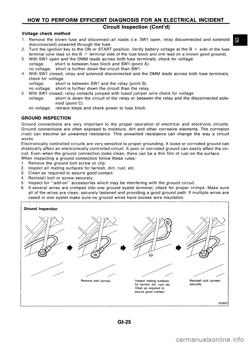
GROUND INSPECTION
Ground connections arevery important tothe proper operation ofelectrical andelectronic circuits.
Ground connections areoften exposed tomoisture, dirtand other corrosive elements. Thecorrosion
(rust) canbecome anunwanted resistance. Thisunwanted resistance canchange theway acircuit
works. Electronically controlledcircuitsarevery sensitive toproper grounding. Aloose orcorroded groundcan
drastically affectanelectronically controlledcircuit.Apoor orcorroded groundcaneasily affectthecir-
cuit. Even when theground connection looksclean, therecanbeathin film ofrust onthe surface.
When inspecting aground connection followtheserules:
1. Remove theground boltscrew orclip.
2. Inspect allmating surfaces fortarnish, dirt,rust, etc.
3. Clean asrequired toassure goodcontact.
4. Reinstall boltorscrew securely.
5. Inspect for"add-on" accessories whichmaybeinterfering withtheground circuit.
6. Ifseveral wiresarecrimped intoone ground eyeletterminal, checkforproper crimps. Makesure
all ofthe wires areclean, securely fastened andproviding agood ground path.Ifmultiple wiresare
cased inone eyelet makesurenoground wireshaveexcess wireinsulation.
Ground Inspection
•
Removeboll(screw).
•
GI-25
Inspect
matingsurfaces
for tarnish. dirt.rust. etc.
Clean asrequired to
assure goodcontact.
•
Reinstallbolt(screw)
securely.
SGI853