set clock NISSAN ALMERA N15 1995 Service Manual
[x] Cancel search | Manufacturer: NISSAN, Model Year: 1995, Model line: ALMERA N15, Model: NISSAN ALMERA N15 1995Pages: 1701, PDF Size: 82.27 MB
Page 305 of 1701
SBR646REAR
DISCBRAKE
Assembly (Cont'd)
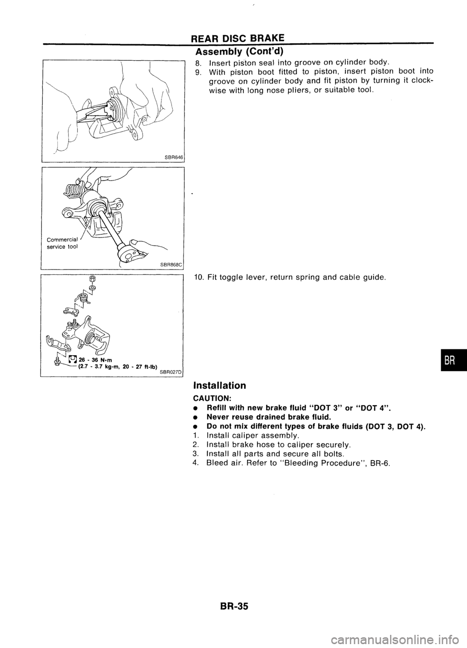
8. Insert piston sealintogroove oncylinder body.
9. With piston bootfitted topiston, insertpiston bootinto
groove oncylinder bodyandfitpiston byturning itclock-
wise withlong nose pliers, orsuitable tool.
Commercial
service
1001
SBR868C
10.Fittoggle lever,return spring andcable guide.
Installation
CAUTION:
• Refill withnewbrake fluid"DOT 3"or"DOT
4".
• Never reusedrained brakefluid.
• Donot mix different typesofbrake fluids(DOT3,DOT
4).
1. Install caliper assembly.
2. Install brakehosetocaliper securely.
3. Install allparts andsecure allbolts.
4. Bleed air.Refer to"Bleeding Procedure", BR-6.
BR-35
•
Page 447 of 1701
Bulbcover
SEL995K HEADLAMP
Bulb Replacement
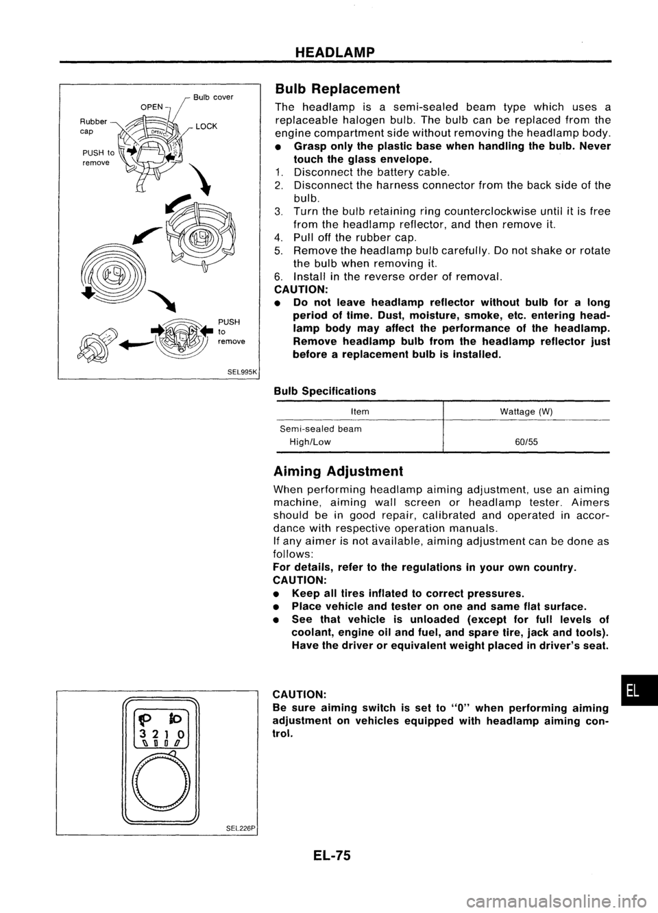
The headlamp isasemi-sealed beamtypewhich usesa
replaceable halogenbulb.Thebulb canbereplaced fromthe
engine compartment sidewithout removing theheadlamp body.
• Grasp onlytheplastic basewhen handling thebulb. Never
touch theglass envelope.
1. Disconnect thebattery cable.
2. Disconnect theharness connector fromtheback sideofthe
bulb.
3. Turn thebulb retaining ringcounterclockwise until
it
is free
from theheadlamp reflector,andthen remove it.
4. Pull offthe rubber cap.
5. Remove theheadlamp bulbcarefully. Donot shake orrotate
the bulb when removing it.
6. Install inthe reverse orderofremoval.
CAUTION:
• Do not leave headlamp reflector withoutbulbforalong
period oftime. Dust,moisture, smoke,etc.entering head-
lamp bodymayaffect theperformance ofthe head lamp.
Remove headlamp bulbfrom thehead lamp reflector just
before areplacement bulbisinstalled.
Bulb Specifications
Item
Semi-sealed beam
High/Low Wattage
(W)
60/55
f>
to
3 21 0
~ nOD
o
SEL226PAiming
Adjustment
When performing headlamp aiming adjustment, useanaiming
machine, aimingwallscreen orheadlamp tester.Aimers
should beingood repair, calibrated andoperated inaccor-
dance withrespective operationmanuals.
If any aimer isnot available, aimingadjustment canbedone as
follows:
For details, refertothe regulations inyour owncountry.
CAUTION:
• Keep alltires inflated tocorrect pressures.
• Place vehicle andtester onone and same flatsurface.
• See thatvehicle isunloaded (exceptforfull levels of
coolant, engineoiland fuel, andspare tire,jack andtools).
Have thedriver orequivalent weightplaced indriver's seat.
CAUTION: •
Be sure aiming switchisset to
"0"
when performing aiming
adjustment onvehicles equipped withheadlamp aiming con-
trol.
EL-75
Page 1093 of 1701
VE-TYPE INJECTION PUMP
SEF779A
Adjustment
INJECTION TIMINGADJUSTMENT (Plunger
lift
adjustment)
Preparation ofcold start device
1. Turn coldstart device linkage clockwise.
2. Set asuitable block[Thickness: about15mm (0.59 in)]
between coldstart device plunger andlinkage rod.
3. Turn crankshaft 2turns clockwise toset the device tonor-
mal position.
Checking
1. Set NO.1 piston atTDC onitscompression stroke.
TDC: Without paintedmark
2. Remove injection tubesandairbleeder onthe back ofinjec-
tion pump.
3. Set dial gauge soitsindicator pointstosomewhere between
1.0 and 2.0mm (0.039 and0.079 in)onthe scale.
4. Turn crankshaft 1turn clockwise andcheck thatdialgauge
indicates thesame value again.
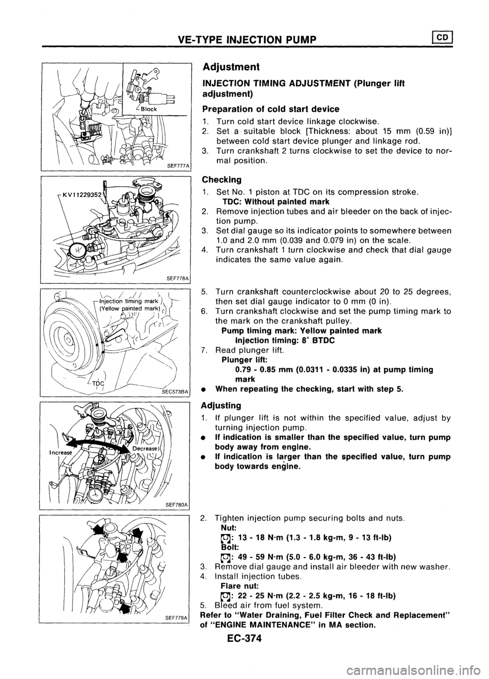
5. Turn crankshaft counterclockwise about20to25 degrees,
then setdial gauge indicator to0mm (0in).
6. Turn crankshaft clockwiseandsetthe pump timing markto
the mark onthe crankshaft pulley.
Pump timing mark:Yellow painted mark
Injection timing:8
0
BTDC
7. Read plunger lift.
Plunger lift:
0.79 -0.85 mm(0.0311 -0.0335 in)atpump timing
mark
• When repeating thechecking, startwithstep 5.
Adjusting
1. Ifplunger liftisnot within thespecified value,adjust by
turning injection pump.
• Ifindication issmaller thanthespecified value,turnpump
body away fromengine.
• Ifindication islarger thanthespecified value,turnpump
body towards engine.
2. Tighten injection pumpsecuring boltsandnuts.
Nut:
~: 13-18 N.m (1.3-1.8 kg-m, 9-13 ft-Ib)
Bolt:
~: 49-59 N.m (5.0-6.0 kg-m, 36-43 ft-Ib)
3. Remove dialgauge andinstall airbleeder withnewwasher.
4. Install injection tubes.
Flare nut:
~: 22-25 N.m (2.2-2.5 kg-m, 16-18 ft-Ib)
5. Bleed airfrom fuelsystem.
Refer to"Water Draining, FuelFilter Check andReplacement"
of "ENGINE MAINTENANCE" inMA section.
EC-374
Page 1202 of 1701
TIMINGCHAIN
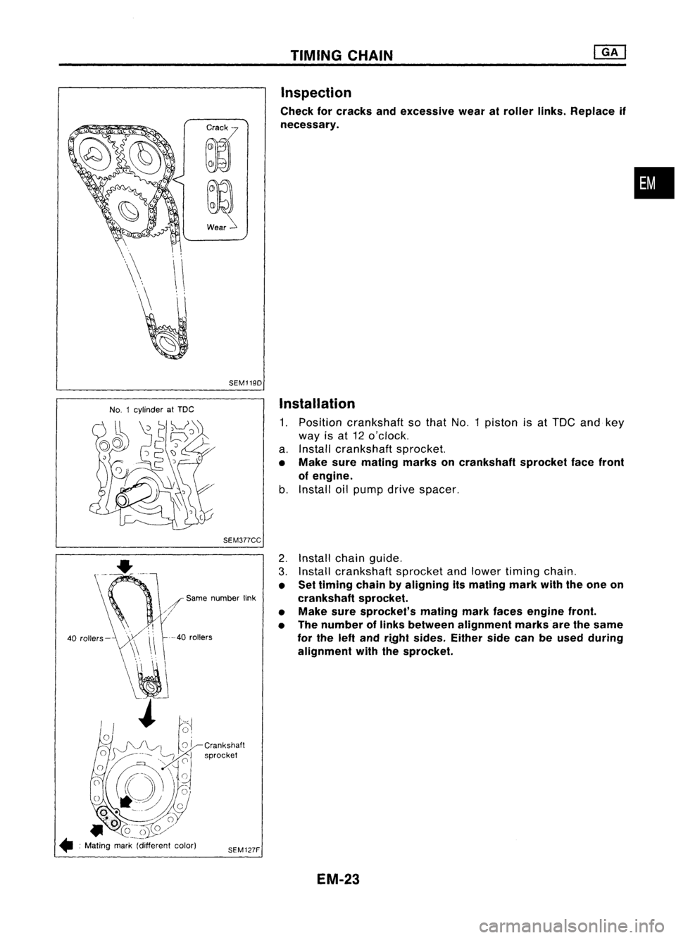
Inspection
Check forcracks andexcessive wearatroller links.Replace if
necessary.
•
SEM1190
No. 1cylinder atTDC
Installation
1. Position crankshaft sothat No.1piston isat TOC andkey
way isat 12 o'clock.
a. Install crankshaft sprocket.
• Make suremating marksoncrankshaft sprocketfacefront
of engine.
b. Install oilpump drivespacer.
SEM377CC
--40
rollers
2.
Install chainguide.
3. Install crankshaft sprocketandlower timing chain.
• Settiming chainbyaligning itsmating markwiththeone on
crankshaft sprocket.
• Make suresprocket's matingmarkfaces engine front.
• The number oflinks between alignment marksare thesame
for the leftand ri.Qht sides. Eithersidecanbeused during
alignment withthesprocket.
SEM127F
/
Same number link
///
40 rollers-
• :Mating mark(different color)
EM-23
Page 1253 of 1701
![NISSAN ALMERA N15 1995 Service Manual
@
~c
t':'
CO',
M''''',mwk
Mating markC
~!
56
coli'" ~
t..
coli."
CD
Mating mark
SEM500E TIMING
CHAIN
[]K]
Installation (Cont'd)
2. Positio NISSAN ALMERA N15 1995 Service Manual
@
~c
t':'
CO',
M''''',mwk
Mating markC
~!
56
coli'" ~
t..
coli."
CD
Mating mark
SEM500E TIMING
CHAIN
[]K]
Installation (Cont'd)
2. Positio](/img/5/57349/w960_57349-1252.png)
@
~c
t':'
CO',
M''''',mwk
Mating markC
~!
56
coli'" ~
t..
coli."
CD
Mating mark
SEM500E TIMING
CHAIN
[]K]
Installation (Cont'd)
2. Position crankshaft sothat No.1 piston isset atTOG andkey
way isat 12 o'clock. Fittiming chainoncrankshaft sprocket,
aligning themating marks.
• Mating markcolorontiming chain.
eD
Gold
@,
CID:
Silver
3. Install timing chainandtiming chainguides.
4. Before installing frontcover, remove alltraces ofliquid
gasket frommating surface usingascraper.
• Also remove tracesofliquid gasket frommating surface of
cylinder block.
5. Apply acontinuous beadofliquid gasket tomating surface
of front cover.
• Use Genuine LiquidGasket orequivalent.
• Besure toinstall newfront oilseal inthe right direction.
Refer toEM-82.
EM-74
Page 1300 of 1701
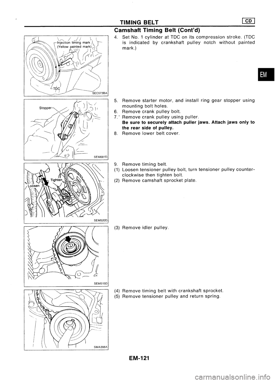
SEM520DSEM515D TIMING
BELT
em
Camshaft TimingBelt(Cont'd)
4. Set NO.1 cylinder atTDC onitscompression stroke.(TDC
is indicated bycrankshaft pulleynotchwithout painted
mark.)
5. Remove startermotor,andinstall ringgear stopper using
mounting boltholes.
6. Remove crankpulley bolt.
7 .. Remove crankpulley usingpuller.
Be sure tosecurely attachpullerjaws.Attach jawsonlyto
the rear sideofpulley.
8. Remove lowerbeltcover.
9. Remove timingbelt.
(1) Loosen tensioner pulleybolt,turntensioner pulleycounter-
clockwise thentighten bolt.
(2) Remove camshaft sprocketplate.
(3) Remove idlerpulley.
(4) Remove timingbeltwith crankshaft sprocket.
(5) Remove tensioner pulleyandreturn spring.
EM-121
•
Page 1303 of 1701
![NISSAN ALMERA N15 1995 Service Manual TIMINGBELT
@[]
Camshaft TimingBelt(Cont'd)
5. Install timing beltwith crankshaft sprocket.
a. Align white linesontiming beltwith punchmarks oncam-
shaft sprocket andcrankshaft sprocket.
b. Poi NISSAN ALMERA N15 1995 Service Manual TIMINGBELT
@[]
Camshaft TimingBelt(Cont'd)
5. Install timing beltwith crankshaft sprocket.
a. Align white linesontiming beltwith punchmarks oncam-
shaft sprocket andcrankshaft sprocket.
b. Poi](/img/5/57349/w960_57349-1302.png)
TIMINGBELT
@[]
Camshaft TimingBelt(Cont'd)
5. Install timing beltwith crankshaft sprocket.
a. Align white linesontiming beltwith punchmarks oncam-
shaft sprocket andcrankshaft sprocket.
b. Point arrow ontiming belttoward beltcover.
6. Install camshaft sprocketplateandsecure screws withlock-
tite.
7. Adjust timing belttension.
1) Loosen tensioner lockbolttoapply tension totiming belt.
2) Rotate crankshaft clockwisetwoturns toapply thespecified
tension totiming belt.
3) Tighten tensioner lockboltwhile holding tensioner pUlley
with hexagon wrench. .
Belt tension:
147.1 :1:24.5 N(15:1:2.5 kg,33.1 :1:5.5 Ib)
SEM520D Injection PumpTiming Belt
~ .N'm (kg-m, in-Ib)
~ :N.m (kg-m, ft-Ib)
SEC.
130-135
~
-"~
.~\(~[-~~' c~1
Timingbelt
?\~-d
(~K.
c
'0
t£
Tensioner spring
J
J
N
0~lJ'00 ~/ Tensioner
t0
J
l\J~.~l:~
'Gl
~')U
r
r~/~
16-21 (1.6 -2.1,12 -15)
It
I
L~0--~ '
~htiJ
JD/~h~J/ "
'SP/
_-z,}) ~A
[/ ......., ....... InJeclion~
.... ~. -;;, pump@J_
• '~~ sprocket~
"fc;,~~-
@ ~
59-
69-.1
Rear camshaft sprocket .~(6.0•7.0,
1m
43-51)
[O;l
87•107
(8.9 -10.9, 64•79)
SEM225F
REMOVAL
1. Set NO.1 cylinder atTDC onitscompression stroke.(TDC
is indicated bycrankshaft pulleynotchwithout painted
mark.)
2. Remove airduct withresonator andtiming beltcover.
EM-124
Page 1304 of 1701
![NISSAN ALMERA N15 1995 Service Manual
InjectionpumppUlley
TIMING
BELT
[fQ]
Injection PumpTiming Belt(Cont'd)
3. Remove timingbelt.
1) Loosen tensioner locknutand turn tensioner clockwise to
free beltfrom tension. Thentemporarily NISSAN ALMERA N15 1995 Service Manual
InjectionpumppUlley
TIMING
BELT
[fQ]
Injection PumpTiming Belt(Cont'd)
3. Remove timingbelt.
1) Loosen tensioner locknutand turn tensioner clockwise to
free beltfrom tension. Thentemporarily](/img/5/57349/w960_57349-1303.png)
InjectionpumppUlley
TIMING
BELT
[fQ]
Injection PumpTiming Belt(Cont'd)
3. Remove timingbelt.
1) Loosen tensioner locknutand turn tensioner clockwise to
free beltfrom tension. Thentemporarily tightentensioner
nut.
2) Remove timingbelt.
INSTAllATION
1. Confirm thatNO.1 piston isset atTDC onitscompression
stroke. (TDCisindicated bycrankshaft pulleynotchwithout
painted mark.)
• Ifinjection pumppulley wasremoved, confirmthatitis
re-installed asillustrated.
Identification ofalignment:
Use mark "A"
2. Set timing belt.
a. Align white linesontiming beltwith punchmarks oncam-
shaft sprocket andinjection pumpsprocket.
b. Point arrow ontiming belttoward beltcover.
3. Adjust belttension.
1) Loosen tensioner locknuttoapply tension totiming belt.
2) Rotate crankshaft clockwisetwoturns.
Do not turn crankshaft bycamshaft sprockets.
3) Tighten tensioner locknutwhile holding tensioner witha
screwdriver.
Belt tension:
147:l:49 N(15:l:5 kg,33:l:11 Ib)
INSPECTION
Refer toINSPECTION in"Camshaft TimingBelt"(EM-122).
INJECTION TIMINGADJUSTMENT
Refer toEC section.
EM-125
•