stop start NISSAN ALMERA N15 1995 Service Manual
[x] Cancel search | Manufacturer: NISSAN, Model Year: 1995, Model line: ALMERA N15, Model: NISSAN ALMERA N15 1995Pages: 1701, PDF Size: 82.27 MB
Page 17 of 1701

Fluidleakage TROUBLE
DIAGNOSES
Preliminary Check(PriortoRoad Testing)
AIT FLUID CHECK
Fluid leakage check
1. Clean areasuspected ofleaking, -for example, mating
surface ofconverter housingandtransmission case.
2. Start engine, applyfootbrake, placeselector leverin"0"
position andwait afew minutes.
3. Stop engine.
4. Check forfresh leakage.
SAT288G
Fluidcondition check
Fluid levelcheck -Refer toMA section (CHASSIS AND
BODY MAINTENANCE).
Fluid
color
Oark orblack withburned odor
Milky pink
Varnished fluid,lighttodark brown
and tacky Suspected
problem
Wear offrictional material
Water contamination
- Road water entering through
filler tubeorbreather
Oxidation
- Over orunder filling
- Overheating
•
Road Testing
Perform roadtests using "Symptom" chart.Refertopage
AT-20.
"P"
POSITION
1. Place selector leverin"P" position andstart engine. Stop
engine andrepeat theprocedure inall positions, including
neutral position.
2. Stop vehicle onaslight upgrade andplace selector leverin
"P" position. Releaseparkingbraketomake surevehicle
remains locked.
"R"
POSITION
1. Manually moveselector leverfrom"P"to"R", andnote
shift quality.
2. Drive vehicle inreverse longenough todetect slippage or
other abnormalities.
"N"
POSITION
1. Manually moveselector leverfrom"R"and"0"to"N" and
note shift quality.
2. Release parkingbrakewithselector leverin"N" position.
Lightly depress accelerator pedaltomake surevehicle
does notmove. (When vehicle isnew orsoon afterclutches
have been replaced, vehiclemaymove slightly. Thisisnot
a problem.)
AT-17
Page 285 of 1701
OKNGBRAKE
BOOSTER
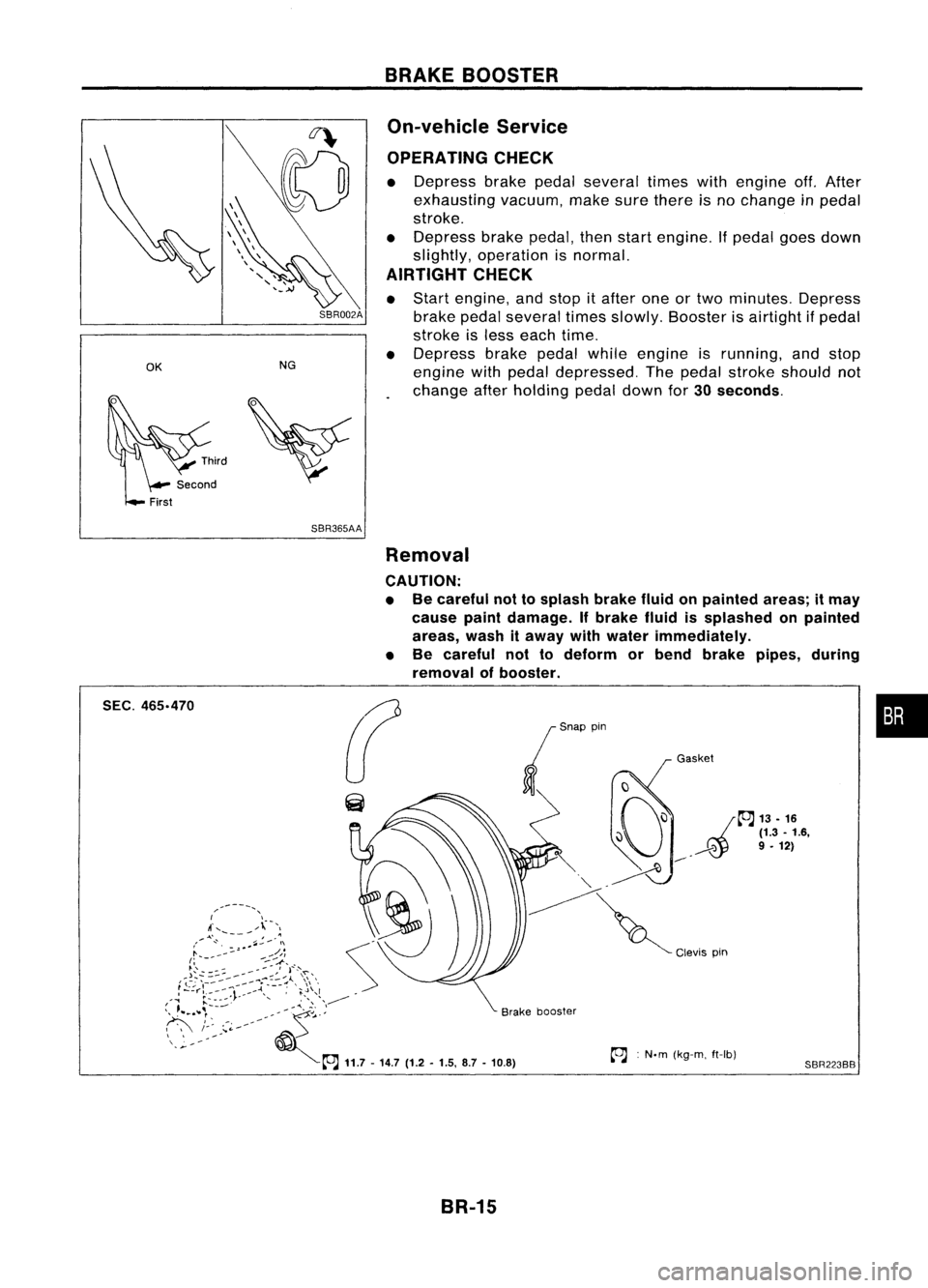
On-vehicle Service
OPERATING CHECK
• Depress brakepedalseveral timeswithengine off.After
exhausting vacuum,makesurethere isno change inpedal
stroke.
• Depress brakepedal, thenstart engine. Ifpedal goesdown
slightly, operation isnormal.
AIRTIGHT CHECK
• Start engine, andstop itafter oneortwo minutes. Depress
SBR002A
brakepedalseveral timesslowly. Booster isairtight ifpedal
stroke isless each time.
• Depress brakepedalwhileengine isrunning, andstop
engine withpedal depressed. Thepedal stroke should not
change afterholding pedaldownfor
30seconds.
SBR365AA Removal
CAUTION:
• Becareful nottosplash brakefluidonpainted areas;itmay
cause paintdamage. Ifbrake fluidissplashed onpainted
areas, washitaway withwater immediately.
• Be careful nottodeform orbend brake pipes, during
removal ofbooster.
SEC.
465.470
BR-15Gasket
~ :N.m (kg-m. ft-Ib)
SBR223BB
•
Page 315 of 1701
ANTI-LOCKBRAKESYSTEM
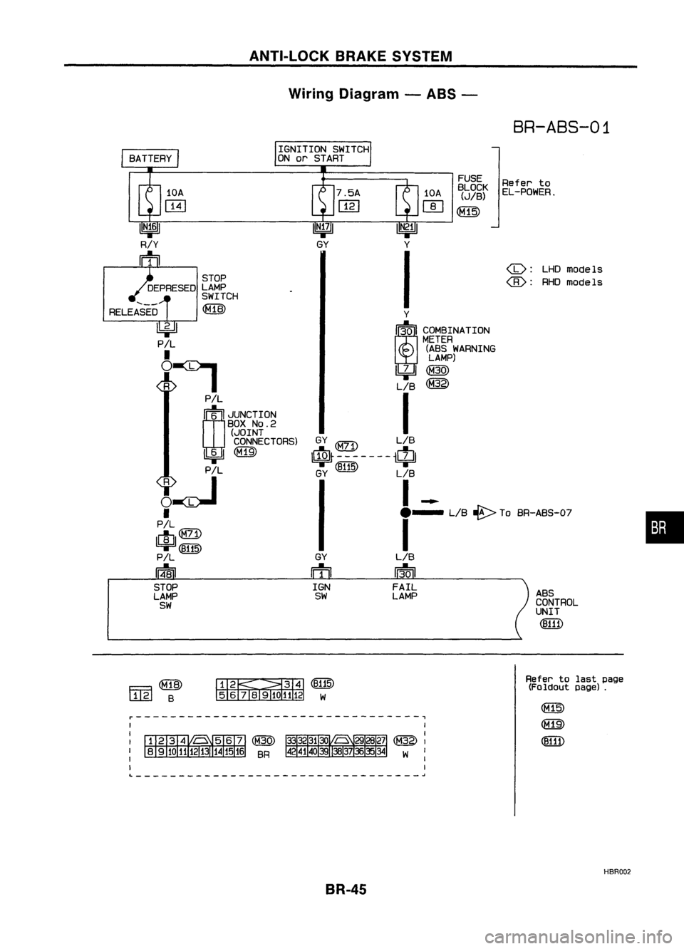
Wiring Diagram -ABS -
BR-ABS-01
•
ABS
CONTROL
UNIT
(B111)
LHDmodels
@:
RHOmodels
Refer
to
EL-POWER.
FUSE
BLOCK
(JIB)
~
GY
ffi
IGN
SW
Y
I~I COMBINATION
METER
(ABS WARNING
LAMP)
~@
LIB
@
I
GY
$-------$
GY (~) LIB
I-
e-
LIB~ ToBR-ABS-O?
I
LIB
13-0
I
FAIL
LAMP
IGNITION
SWITCH
ON orSTART
STOP
DEPRESED LAMP
SWITCH
RELEASED ~
~
P!L
•
~:I
P!L
rn~
I
JUNCTION
BOX
NO.2
(JOINT
CONNECTORS)
1!:i=!J~
PIL
~~
•
PIL
lelIl
9F'~
P!L
14-81
STOP
LAMP
SW
Fa~
l..1..@
B ~~(B115)
5 6
TI1910
1112 W
Refer
tolast page
(Foldout page).
~---------------------------------,
L ~
HBR002
BR-45
Page 322 of 1701
TROUBLEDIAGNOSES
Contents
How toPerform TroubleDiagnoses forQuick andAccurate Repair SR-52
Self-diagnosis SR-53
CONSULT BR-58
CONSULT Inspection Procedure BR-59
Component PartsandHarness Connector Location BR-64
Preliminary Check BR-65
Ground CircuitCheck BR-66
Circuit Diagram forQuick Pinpoint Check BR-67
Diagnostic Procedure1Warning lampdoes notcome on BR-68
Diagnostic Procedure2Warning lampstays on BR-69
Diagnostic Procedure3ABS actuator solenoid valve BR-72
Diagnostic Procedure 4Wheel sensor orrotor BR-74
Diagnostic Procedure5Motor relayormotor BR-76
Diagnostic Procedure6Solenoid valverelay BR-79
Diagnostic Procedure7Power supply BR-81
Diagnostic Procedure 8Control unit BR-82
Diagnostic Procedure9Pedal vibration andnoise BR-82
Diagnostic Procedure10Long stopping distance BR-83
Diagnostic Procedure11Unexpected pedalaction BR-83
Diagnostic Procedure12ABS does notwork BR-84
Diagnostic Procedure13ABS works frequently BR-84
Electrical Component Inspection BR-85
How toPerform TroubleDiagnoses forQuick
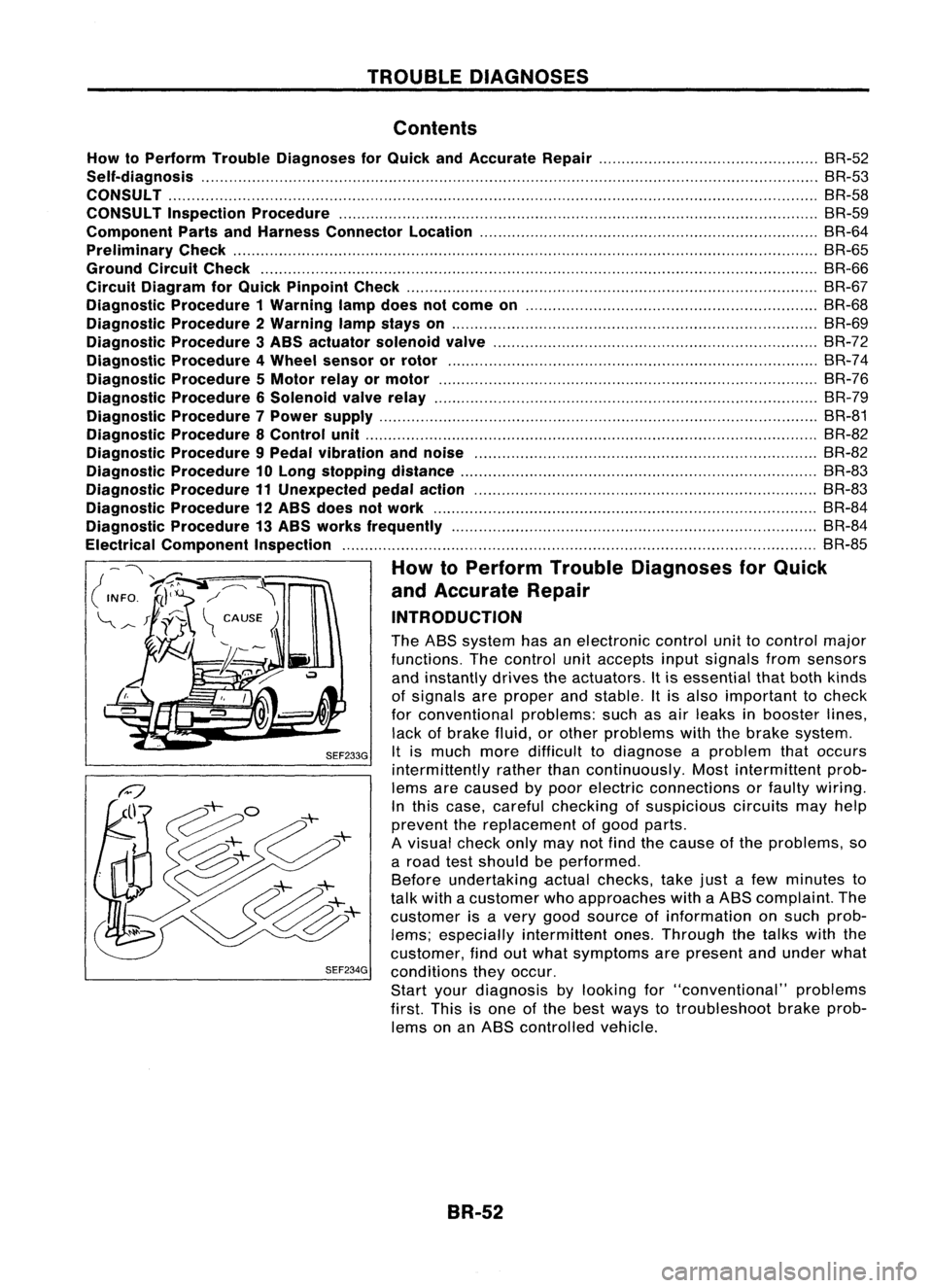
and Accurate Repair
INTRODUCTION
The ABS system hasanelectronic controlunittocontrol major
functions. Thecontrol unitaccepts inputsignals fromsensors
and instantly drivestheactuators. Itis essential thatboth kinds
of signals areproper andstable. Itis also important tocheck
for conventional problems:suchasair leaks inbooster lines,
lack ofbrake fluid,orother problems withthebrake system.
SEF233G
Itis much moredifficult todiagnose aproblem thatoccurs
intermittently ratherthancontinuously. Mostintermittent prob-
lems arecaused bypoor electric connections orfaulty wiring.
In this case, careful checking ofsuspicious circuitsmayhelp
prevent thereplacement ofgood parts.
A visual checkonlymaynotfind thecause ofthe problems, so
a road testshould beperformed.
Before undertaking actualchecks, takejustafew minutes to
talk with acustomer whoapproaches withaABS complaint. The
customer isavery good source ofinformation onsuch prob-
lems; especially intermittent ones.Through thetalks withthe
customer, findoutwhat symptoms arepresent andunder what
SEF234G
conditions theyoccur.
Start yourdiagnosis bylooking for"conventional" problems
first. Thisisone ofthe best ways totroubleshoot brakeprob-
lems onanABS controlled vehicle.
BR-52
Page 323 of 1701
.=J
MPH
-~s::~
~~
___ --- warnin:1
TROUBLE
DIAGNOSES
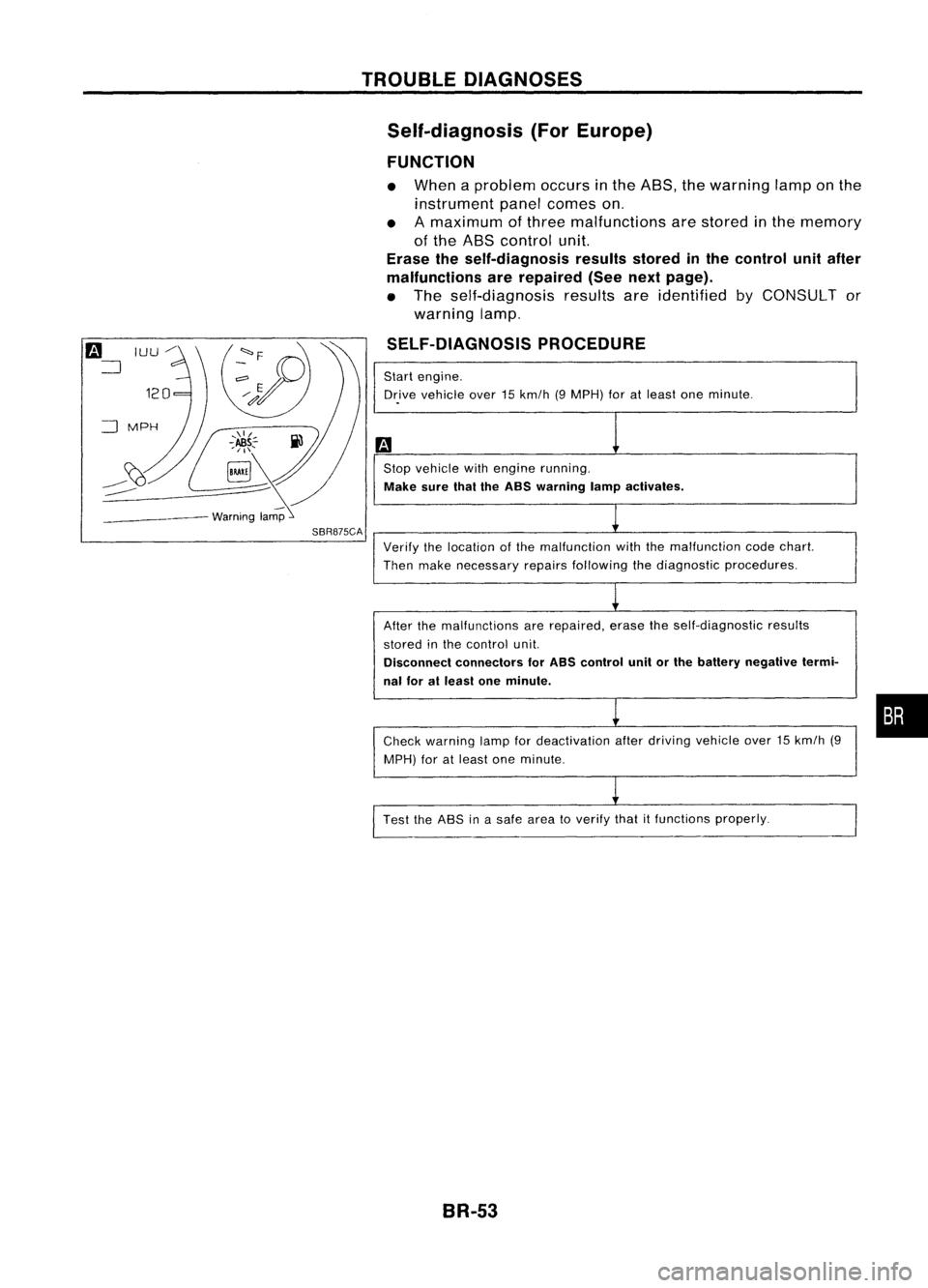
Self-diagnosis (ForEurope)
FUNCTION
• When aproblem occursinthe ABS, thewarning lamponthe
instrument panelcomes on.
• Amaximum ofthree malfunctions arestored inthe memory
of the ABS control unit.
Erase theself-diagnosis resultsstoredinthe control unitafter
malfunctions arerepaired (Seenextpage).
• The self-diagnosis resultsareidentified byCONSULT or
warning lamp.
SELF-DIAGNOSIS PROCEDURE
Start engine.
Dr.ive vehicle over15km/h (9MPH) foratleast oneminute .
Stop vehicle withengine running.
Make surethaitheASS warning lampactivates.
SBR875CA
Verifythelocation ofthe malfunction withthemalfunction codechart.
Then make necessary repairsfollowing thediagnostic procedures.
After themalfunctions arerepaired, erasetheself-diagnostic results
stored inthe control unit.
Disconnect connectors forASS control unitorthe battery negative termi-
nal foratleast oneminute.
Check warning lampfordeactivation afterdriving vehicle over15km/h (9
MPH) foratleast oneminute.
Test theASS inasafe area toverify thatitfunctions properly.
BR-53
•
Page 329 of 1701
![NISSAN ALMERA N15 1995 Service Manual TROUBLEDIAGNOSES
Ii)
NISSAN
CONSULT
EE940.
I
~
I
START
I
SUB
MODE
,
SEF253Q
@]
~
SELECT
SYSTEM
0
ENGINE
AfT
AIRBAG ABS
IVMS
SBR104D
@]
I~
SELECT DIAGMODE
01
I
SELF-DIAG
RESULTS NISSAN ALMERA N15 1995 Service Manual TROUBLEDIAGNOSES
Ii)
NISSAN
CONSULT
EE940.
I
~
I
START
I
SUB
MODE
,
SEF253Q
@]
~
SELECT
SYSTEM
0
ENGINE
AfT
AIRBAG ABS
IVMS
SBR104D
@]
I~
SELECT DIAGMODE
01
I
SELF-DIAG
RESULTS](/img/5/57349/w960_57349-328.png)
TROUBLEDIAGNOSES
Ii)
NISSAN
CONSULT
EE940.
I
~
I
START
I
SUB
MODE
,
SEF253Q
@]
~
SELECT
SYSTEM
0
ENGINE
AfT
AIRBAG ABS
IVMS
SBR104D
@]
I~
SELECT DIAGMODE
01
I
SELF-DIAG
RESULTS
,
I
DATA
MONITOR
I
I
ACTIVE
TEST
I
ECU
PART NUMBER
I
I
SST412B
II
•SELF-DiAG RESULTS.
0
FAILURE DETECTED
TIME
FR RH SENSOR
0
[OPEN)
ERASE
II
PRINT
SBR950C CONSULT
Inspection Procedure
SELF-DIAGNOSIS PROCEDURE
m
1) Turn ignition switchOFF.
2) Connect CONSULT toData LinkCon-
nector forCONSULT.
1) Start engine.
2) Drive vehicle over30km/h (20MPH)
for atleast oneminute.
.
r
(;)
1)Stop vehicle withengine running
and touch "START" onCON-
SUL Tscreen.
• Program
card
AE950: ForAustralia
EE940: ExceptAustralia
(!]
2)Touch "ASS".
lP]
3)Touch "SELF-DIAG RESULTS".
• The screen showsthedetected mal-
function andthetimes ofignition
switch ONand OFF after itoccurred.
Make thenecessary repairsfollowing
the diagnostic procedures.
II
After themalfunctions arerepaired,
erase theself-diagnostic resultsstored
in the control unitbytouching
"ERASE".
Check warning lampfordeactivation
after driving vehicle over30km/h (20
MPH) foratleast oneminute.
Test theASS inasafe area toverify
that itfunctions properly.
Note: "SELF.DlAG RESULTS"screenshowsthedetected malfunction and
the times ofignition switchONand OFF after
it
occurred.
BR-59
•
Page 333 of 1701

DATAMONITOR MODE TROUBLE
DIAGNOSES
CONSULT Inspection Procedure(Cont'd)
MONITOR ITEM CONDITION
SPECIFICATION
FR RH SENSOR
FR LHSENSOR Drive
vehicle.
Almostthesame speed asspeedometer.
REAR RHSENSOR (Each
wheel isrotating.)
REAR LHSENSOR
STOP LAMP SW Brake
isdepressed. Depress
thepedal: ON
Release thepedal: OFF
FR RH INSOL
FR RH OUT SOL
FR LH INSOL
FR LH OUT SOL
Engineisrunning. Operating
conditions foreach solenoid valveareindicated.
RR RH INSOL ABS
isnot operating: OFF
RR RH OUT SOL
.
RR LHINSOL
RR LHOUT SOL
IgnitionswitchON(Engine stops):OFF
ACTUATOR RLY
Enginerunning: ON
MOTOR RELAY ABS
isnot operating: OFF
Ignition switchisON or
ABSisoperating: ON
engine isrunning.
WARNING LAMP Warning
lampisturned on:ON
Warning lampisturned off:OFF
BATTERY VOLT Power
supply voltage forcontrol unit
ACTIVE TESTMODE
TEST ITEM CONDITION JUDGEMENT
Brake fluidpressure controloperation
FR RH SOLENOID
INSOL OUTSOL
FR LH SOLENOID
RR RH SOLENOID UP
(Increase): OFF OFF
RR LHSOLENOID
Engineisrunning. KEEP
(Hold): ON OFF
DOWN (Decrease): ON ON
ABS actuator motor
ABS MOTOR ON:
Motor runs
OFF: Motor stops
Note: Active testwillautomatically stoptenseconds afterthe
test starts. (LIMIT SIGNAL monitorshowsON.)
BR-63
•
Page 352 of 1701

TROUBLEDIAGNOSES
Diagnostic Procedure8
CONTROL UNIT
(Malfunction codeNo.71)
Carry outself-diagnosis aftererasing
self-diagnostic results,BR-56.
Does warning lampindicate codeNo.
71 again?
No
Inspect thesystem according tothe
code No. Yes
Replace controlunit.
Brake pedal Diagnostic
Procedure9
SYMPTOM: Pedalvibration andnoise
No
Does thesymptom appearwhenelectri-
SAT797A
calequipment switches(suchashead-
lamp) areoperated?
1.
Apply brake.
2. Start engine.
3. Does thesymptom appearonlywhen
engine isstarted?
No
Yes
Check wheelsensor shieldgrou.nd
secured withcontrol unitmounting bolt.
Refer toBR-41. Yes
Carryoutself-diagnosis.
Refer toBR-53 (Europe)
or BR-56 (Except
Europe).
Go to
Ii1
inDiagnostic
Procedure 11,BR-83.
OK
Check control unitpinterminals for
damage orthe connection ofcontrol
unit harness connector.
Reconnect controlunitharness connec-
tor. Then retest.
Note: ABSmayoperate andcause vibration underanyofthe
following conditions.
• Applying brakegradually whenshifting oroperating clutch.
• Low friction (slippery) road.
• High speed cornering.
• Driving overbumps andpotholes.
• Engine speedisover 5,000 rpmwith vehicle stopped.
BR-82
Page 373 of 1701
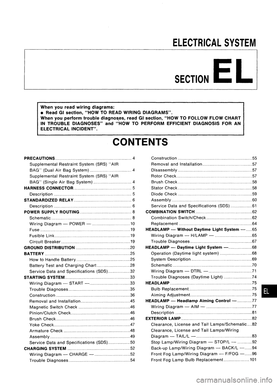
ELECTRICALSYSTEM
SECTION
EL
When youread wiring diagrams:
• Read GIsection, "HOWTOREAD WIRING DIAGRAMS".
When youperform troublediagnos.es, readGIsection, "HOWTOFOllOW FLOWCHART
IN TROUBLE DIAGNOSES" and"HOW TOPERFORM EFFICIENT DIAGNOSIS FORAN
ELECTRICAL INCIDENT".
CONTENTS
PRECAUTIONS 4
Supplemental RestraintSystem(SRS)"AIR
BAG" (DualAirBag System) 4
Supplemental RestraintSystem(SRS)"AIR
BAG" (Single AirBag System) 4
HARNESS CONNECTOR 5
Description 5
STANDARDIZED RELAy 6
Description 6
POWER SUPPLY ROUTING 8
Schematic 8
Wiring Diagram -POWER - 10
Fuse 19
Fusible Link 19
Circuit Breaker 19
GROUND DISTRIBUTION 20
BATTERy 25
How toHandle Battery 25
Battery TestandCharging Chart.. 28
Service DataandSpecifications (SOS) 32
STARTING SySTEM
33
Wiring Diagram -START - 33
Trouble Diagnoses 35
Construction 36
Removal andInstallation .45
Magnetic SwitchCheck .46
Pinion/Clutch Check 46
Brush Check 46
Yoke Check 47
Armature Check 48
Assembly .49
Service DataandSpecifications (SDS) 50
CHARGING SYSTEM 52
Wiring Diagram -CHARGE - 52
Trouble Diagnoses 54Construction
55
Removal andInstallation 57
Disassembly 57
Rotor Check 57
Brush Check 58
Stator Check 58
Diode Check 59
Assembly 60
Service DataandSpecifications (SDS) 61
COMBINATION SWITCH 62
Combination Switch/Check 62
Replacement 64
HEADLAMP -Without Daytime lightSystem -65
Wiring Diagram -H/LAMP - 65
Trouble Diagnoses 67
HEADLAMP -Daytime lightSystem - 68
Operation (Daytimelightsystem) 68
System Description 69
Schematic 70
Wiring Diagram -DTRL - 71
Trouble Diagnoses (DaytimeLight) 74
HEADLAMP 75
Bulb Replacement... 75•
Aiming Adjustment. 75
HEADLAMP -Headlamp Aiming
Control- 77
Wiring Diagram -AIM - 77
Description 81
EXTERIOR LAMP 82
Clearance, LicenseandTail Lamps/Schematic 82
Clearance, LicenseandTail Lamps/Wiring
Diagram -TAILIL - 83
Stop Lamp/Wiring Diagram-STOP/L - 92
Back-up Lamp/Wiring Diagram-BACK/L -94
Front FogLamp/Wiring Diagram-F/FOG -96
Front FogLamp BulbReplacement 101
Page 381 of 1701
![NISSAN ALMERA N15 1995 Service Manual POWERSUPPLY ROUTING
Schematic (Cont'd)
l5A~
F/FOG
20A
@J
LOAD,DEF
lOA
[8J
ABS,SToP/L
lOA
[ill
TURN
FICO, A!CCUT,
HEATER, A!e
HEATER, A!e
7.5A@Q]
lOA
@]
l5A
[ill
INT/L
GLOW, AIM,BUZZ NISSAN ALMERA N15 1995 Service Manual POWERSUPPLY ROUTING
Schematic (Cont'd)
l5A~
F/FOG
20A
@J
LOAD,DEF
lOA
[8J
ABS,SToP/L
lOA
[ill
TURN
FICO, A!CCUT,
HEATER, A!e
HEATER, A!e
7.5A@Q]
lOA
@]
l5A
[ill
INT/L
GLOW, AIM,BUZZ](/img/5/57349/w960_57349-380.png)
POWERSUPPLY ROUTING
Schematic (Cont'd)
l5A~
F/FOG
20A
@J
LOAD,DEF
lOA
[8J
ABS,SToP/L
lOA
[ill
TURN
FICO, A!CCUT,
HEATER, A!e
HEATER, A!e
7.5A@Q]
lOA
@]
l5A
[ill
INT/L
GLOW, AIM,BUZZER,
HORN, AUDIO, NATS
ILL, AUDIO
WIP/R
ACCESSORY
RELAY
20A
[ill
lOA ~
l5A ~ HORN
WIPER
MIRROR, DEF
HLC
20A []]
•
LOAD,
DEF
LOAD, MIL,BUZZER, WINDOW,
SROOF, DEF,NATS
LKUP, AIT,BACK/L,
METER, WARN
TURN
ABS
H/SEAT
H02S
F/PUMP, AIRREG
SRS
SRS
PGC/V, EGRC/V, AAC/V,VTC,
COOL/F, LOAD,GLOW,PLA,
FCUT, A/C,START, DTRL,DEF
3A
IE]
lOA
[ill
lOA
[ill
lOA ~
l5A
@]
7.
5A
[ill
n
IGNITION
U
RELAY
TAIL. F/FoG
LOAD, AIM,TAIL, F/FO~
ILL, BUZZER
RHO
models
eo engine
SR engine
SR engine A/Tmodels
and COengine
For Europe andIsrael
Except
@
LHD models without
daytime lightsystem
Except
@
LHo models with
daytime lightsystem
Without daytime lightsystem
With single airbag system
With dualairbag system
@
@
@
@
@
@
@
@
@
@
@
@)
HEL096
EL-9