ECU NISSAN ALMERA N16 2001 Electronic Owners Manual
[x] Cancel search | Manufacturer: NISSAN, Model Year: 2001, Model line: ALMERA N16, Model: NISSAN ALMERA N16 2001Pages: 2493, PDF Size: 66.97 MB
Page 1386 of 2493
Diagnostic ProcedureNJAT0278
1 CHECK DTC WITH ECM
Perform diagnostic test mode II (self- diagnostic results) for engine control. Check ignition signal circuit condition.
OK or NG
OK (With CONSULT-II)©GO TO 2.
OK (Without CONSULT-
II)©GO TO 3.
NG©Check ignition signal circuit for engine control. Refer to EC-451, ªIGNITION SIGNALº.
2 CHECK INPUT SIGNAL (With CONSULT-II)
With CONSULT-II
1. Start engine.
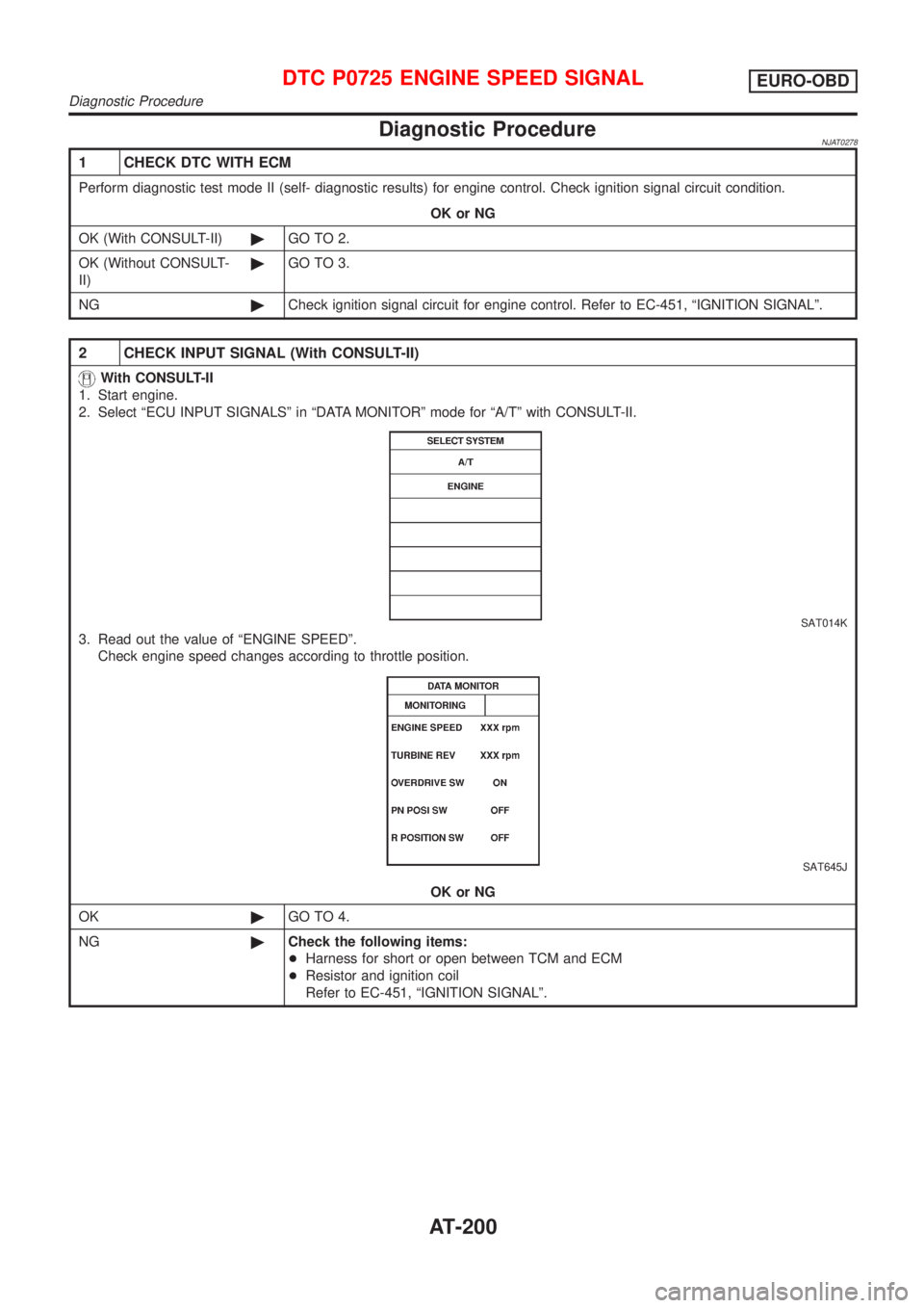
2. Select ªECU INPUT SIGNALSº in ªDATA MONITORº mode for ªA/Tº with CONSULT-II.
SAT014K
3. Read out the value of ªENGINE SPEEDº.
Check engine speed changes according to throttle position.
SAT645J
OK or NG
OK©GO TO 4.
NG©Check the following items:
+Harness for short or open between TCM and ECM
+Resistor and ignition coil
Refer to EC-451, ªIGNITION SIGNALº.
DTC P0725 ENGINE SPEED SIGNALEURO-OBD
Diagnostic Procedure
AT-200
Page 1443 of 2493
ON BOARD DIAGNOSIS LOGICNJAT0311S03
Diagnostic trouble code Malfunction is detected when ... Check items (Possible cause)
: TP SEN/CIRC A/T
TCM receives an excessively low or high
voltage from the sensor.+Harness or connectors
(The sensor circuit is open or shorted.)
+Throttle position sensor
+Throttle position switch
: P1705
SAT014K
SAT971J
SAT014K
SAT020K
DIAGNOSTIC TROUBLE CODE (DTC) CONFIRMATION
PROCEDURE
NJAT0311S04CAUTION:
Always drive vehicle at a safe speed.
NOTE:
If ªDIAGNOSTIC TROUBLE CODE CONFIRMATION PROCE-
DUREº has been previously conducted, always turn ignition
switch ªOFFº and wait at least 5 seconds before conducting
the next test.
After the repair, perform the following procedure to confirm the
malfunction is eliminated.
With CONSULT-II
1) Apply vacuum to the throttle opener, then check the following.
Refer to steps from 1 to 5 of ªPreparationº, ªTCM SELF-DIAG-
NOSTIC PROCEDURE (No Tools)º, AT-61.
2) Turn ignition switch ªONº and select ªDATA MONITORº mode
for ªA/Tº with CONSULT-II.
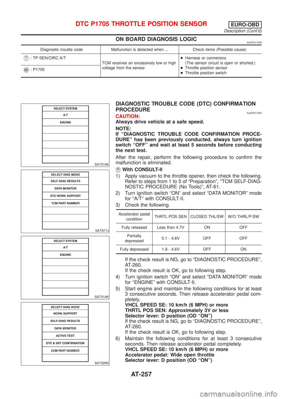
3) Check the following.
Accelerator pedal
conditionTHRTL POS SEN CLOSED THL/SW W/O THRL/P´SW
Fully released Less than 4.7V ON OFF
Partially
depressed0.1 - 4.6V OFF OFF
Fully depressed 1.9 - 4.6V OFF ON
If the check result is NG, go to ªDIAGNOSTIC PROCEDUREº,
AT-260.
If the check result is OK, go to following step.
4) Turn ignition switch ªONº and select ªDATA MONITORº mode
for ªENGINEº with CONSULT-II.
5) Start engine and maintain the following conditions for at least
3 consecutive seconds. Then release accelerator pedal com-
pletely.
VHCL SPEED SE: 10 km/h (6 MPH) or more
THRTL POS SEN: Approximately 3V or less
Selector lever: D position (OD ªONº)
If the check result is NG, go to ªDIAGNOSTIC PROCEDUREº,
AT-260.
If the check result is OK, go to following step.
6) Maintain the following conditions for at least 3 consecutive
seconds. Then release accelerator pedal completely.
VHCL SPEED SE: 10 km/h (6 MPH) or more
Accelerator pedal: Wide open throttle
Selector lever: D position (OD ªONº)
DTC P1705 THROTTLE POSITION SENSOREURO-OBD
Description (Cont'd)
AT-257
Page 1446 of 2493
Diagnostic ProcedureNJAT0313
1 CHECK DTC WITH ECM
Perform diagnostic test mode II (self-diagnostic results) for engine control.
Refer to EC-72, ªMalfunction Indicator (MI)º.
OK or NG
OK (With CONSULT-II)©GO TO 2.
OK (Without CONSULT-
II)©GO TO 3.
NG©Check throttle position sensor circuit for engine control. Refer to EC-168, ªDTC P0120
THROTTLE POSITION SENSORº.
2 CHECK INPUT SIGNAL (WITH CONSULT-II)
With CONSULT-II
1. Apply vacuum to the throttle opener then check the following. Refer from step 1 to 5 of ªPreparationº, ªTCM SELF-DI-
AGNOSTIC PROCEDURE (No Tools)º, AT-61.
2. Turn ignition switch to ªONº position.
(Do not start engine.)
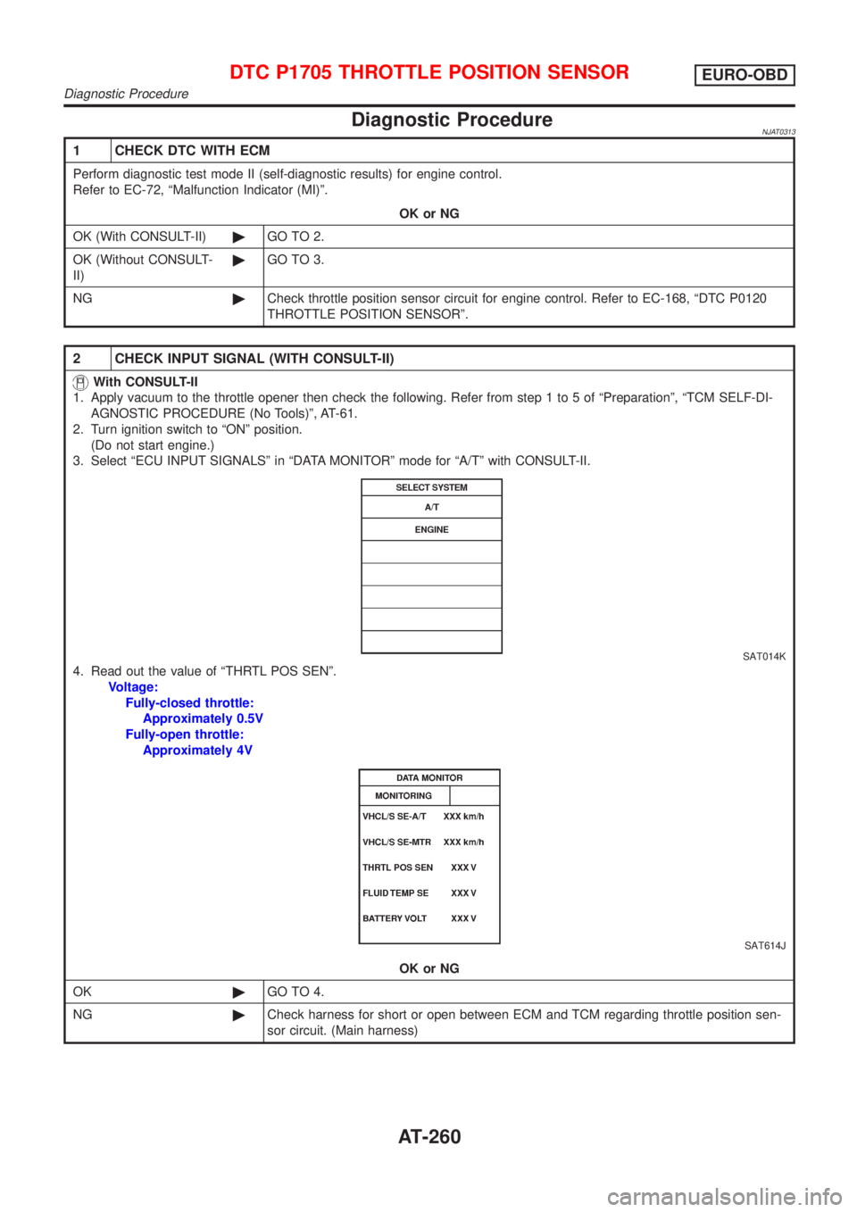
3. Select ªECU INPUT SIGNALSº in ªDATA MONITORº mode for ªA/Tº with CONSULT-II.
SAT014K
4. Read out the value of ªTHRTL POS SENº.
Voltage:
Fully-closed throttle:
Approximately 0.5V
Fully-open throttle:
Approximately 4V
SAT614J
OK or NG
OK©GO TO 4.
NG©Check harness for short or open between ECM and TCM regarding throttle position sen-
sor circuit. (Main harness)
DTC P1705 THROTTLE POSITION SENSOREURO-OBD
Diagnostic Procedure
AT-260
Page 1448 of 2493
4 CHECK THROTTLE POSITION SWITCH CIRCUIT (WITH CONSULT-II)
With CONSULT-II
1. Apply vacuum to the throttle opener, then check the following. Refer to steps 1 to 5 of ªPreparationº, ªTCM SELF-DIAG-
NOSTIC PROCEDURE (No Tools)º, AT-61.
2. Turn ignition switch to ªONº position.
(Do not start engine.)
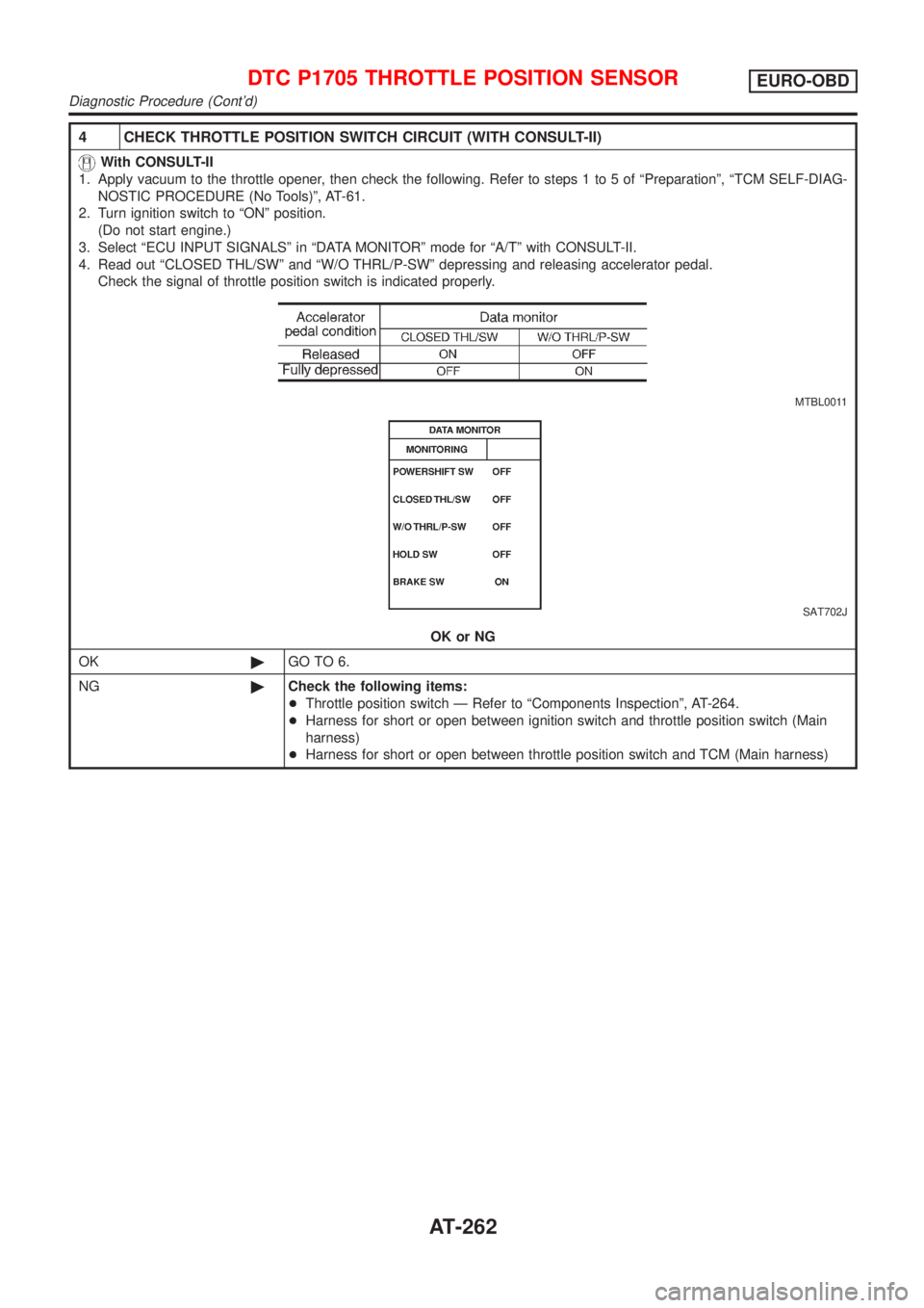
3. Select ªECU INPUT SIGNALSº in ªDATA MONITORº mode for ªA/Tº with CONSULT-II.
4. Read out ªCLOSED THL/SWº and ªW/O THRL/P-SWº depressing and releasing accelerator pedal.
Check the signal of throttle position switch is indicated properly.
MTBL0011
SAT702J
OK or NG
OK©GO TO 6.
NG©Check the following items:
+Throttle position switch Ð Refer to ªComponents Inspectionº, AT-264.
+Harness for short or open between ignition switch and throttle position switch (Main
harness)
+Harness for short or open between throttle position switch and TCM (Main harness)
DTC P1705 THROTTLE POSITION SENSOREURO-OBD
Diagnostic Procedure (Cont'd)
AT-262
Page 1461 of 2493
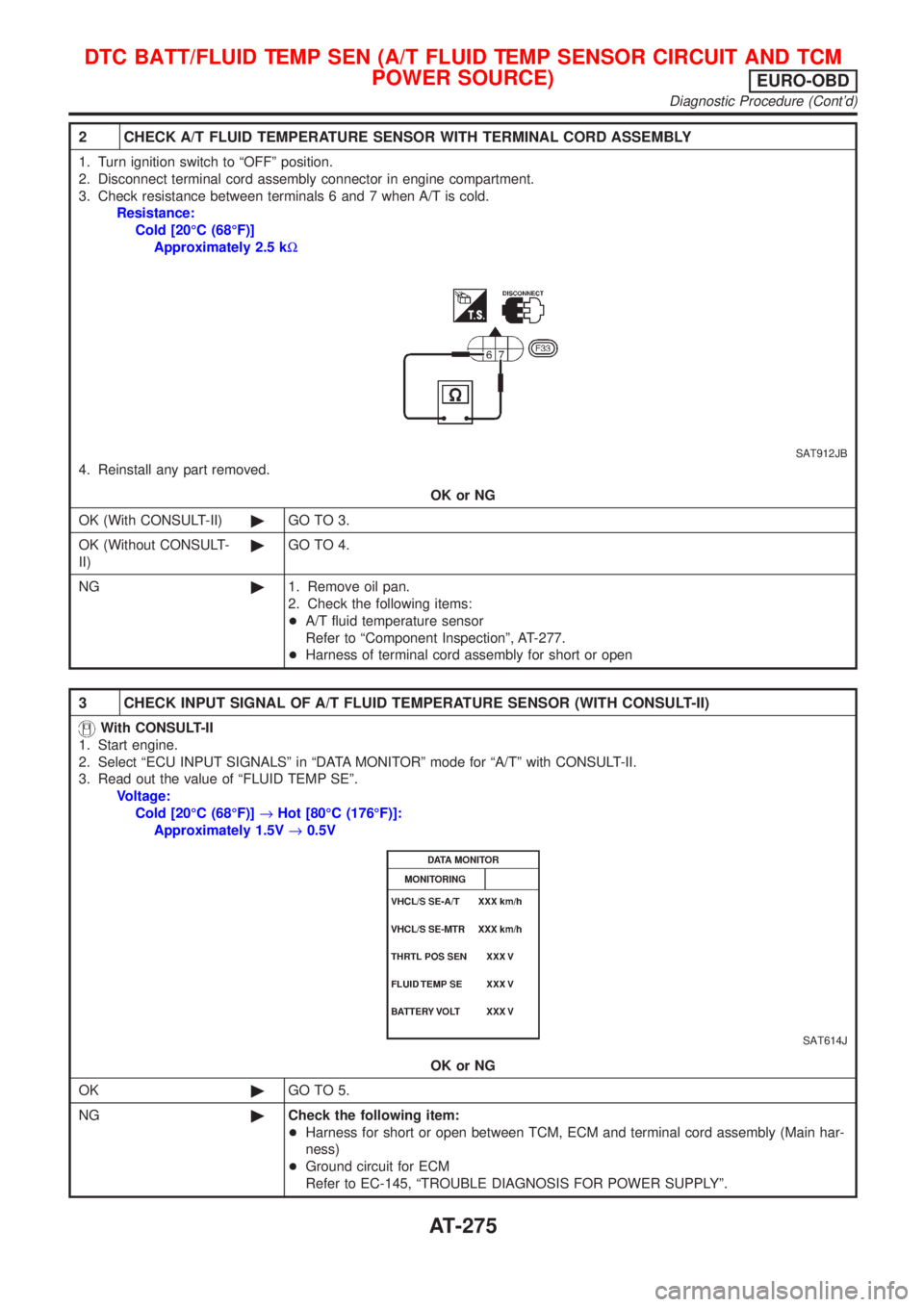
2 CHECK A/T FLUID TEMPERATURE SENSOR WITH TERMINAL CORD ASSEMBLY
1. Turn ignition switch to ªOFFº position.
2. Disconnect terminal cord assembly connector in engine compartment.
3. Check resistance between terminals 6 and 7 when A/T is cold.
Resistance:
Cold [20ÉC (68ÉF)]
Approximately 2.5 kW
SAT912JB
4. Reinstall any part removed.
OK or NG
OK (With CONSULT-II)©GO TO 3.
OK (Without CONSULT-
II)©GO TO 4.
NG©1. Remove oil pan.
2. Check the following items:
+A/T fluid temperature sensor
Refer to ªComponent Inspectionº, AT-277.
+Harness of terminal cord assembly for short or open
3 CHECK INPUT SIGNAL OF A/T FLUID TEMPERATURE SENSOR (WITH CONSULT-II)
With CONSULT-II
1. Start engine.
2. Select ªECU INPUT SIGNALSº in ªDATA MONITORº mode for ªA/Tº with CONSULT-II.
3. Read out the value of ªFLUID TEMP SEº.
Voltage:
Cold [20ÉC (68ÉF)]®Hot [80ÉC (176ÉF)]:
Approximately 1.5V®0.5V
SAT614J
OK or NG
OK©GO TO 5.
NG©Check the following item:
+Harness for short or open between TCM, ECM and terminal cord assembly (Main har-
ness)
+Ground circuit for ECM
Refer to EC-145, ªTROUBLE DIAGNOSIS FOR POWER SUPPLYº.
DTC BATT/FLUID TEMP SEN (A/T FLUID TEMP SENSOR CIRCUIT AND TCM
POWER SOURCE)
EURO-OBD
Diagnostic Procedure (Cont'd)
AT-275
Page 1467 of 2493
Diagnostic ProcedureNJAT0325
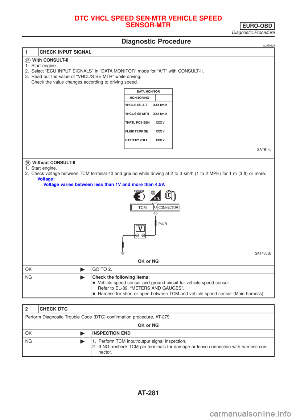
1 CHECK INPUT SIGNAL
With CONSULT-II
1. Start engine.
2. Select ªECU INPUT SIGNALSº in ªDATA MONITORº mode for ªA/Tº with CONSULT-II.
3. Read out the value of ªVHCL/S SE´MTRº while driving.
Check the value changes according to driving speed.
SAT614J
Without CONSULT-II
1. Start engine.
2. Check voltage between TCM terminal 40 and ground while driving at 2 to 3 km/h (1 to 2 MPH) for1m(3ft)ormore.
Voltage:
Voltage varies between less than 1V and more than 4.5V.
SAT465JB
OK or NG
OK©GO TO 2.
NG©Check the following items:
+Vehicle speed sensor and ground circuit for vehicle speed sensor
Refer to EL-89, ªMETERS AND GAUGESº.
+Harness for short or open between TCM and vehicle speed sensor (Main harness)
2 CHECK DTC
Perform Diagnostic Trouble Code (DTC) confirmation procedure, AT-279.
OK or NG
OK©INSPECTION END
NG©1. Perform TCM input/output signal inspection.
2. If NG, recheck TCM pin terminals for damage or loose connection with harness con-
nector.
DTC VHCL SPEED SEN´MTR VEHICLE SPEED
SENSOR´MTR
EURO-OBD
Diagnostic Procedure
AT-281
Page 1477 of 2493
2. Engine Cannot Be Started In ªPº and ªNº
Position
=NJAT0332SYMPTOM:
+Engine cannot be started with selector lever in ªPº or ªNº
position.
+Engine can be started with selector lever in ªDº, ª2º, ª1º
or ªRº position.
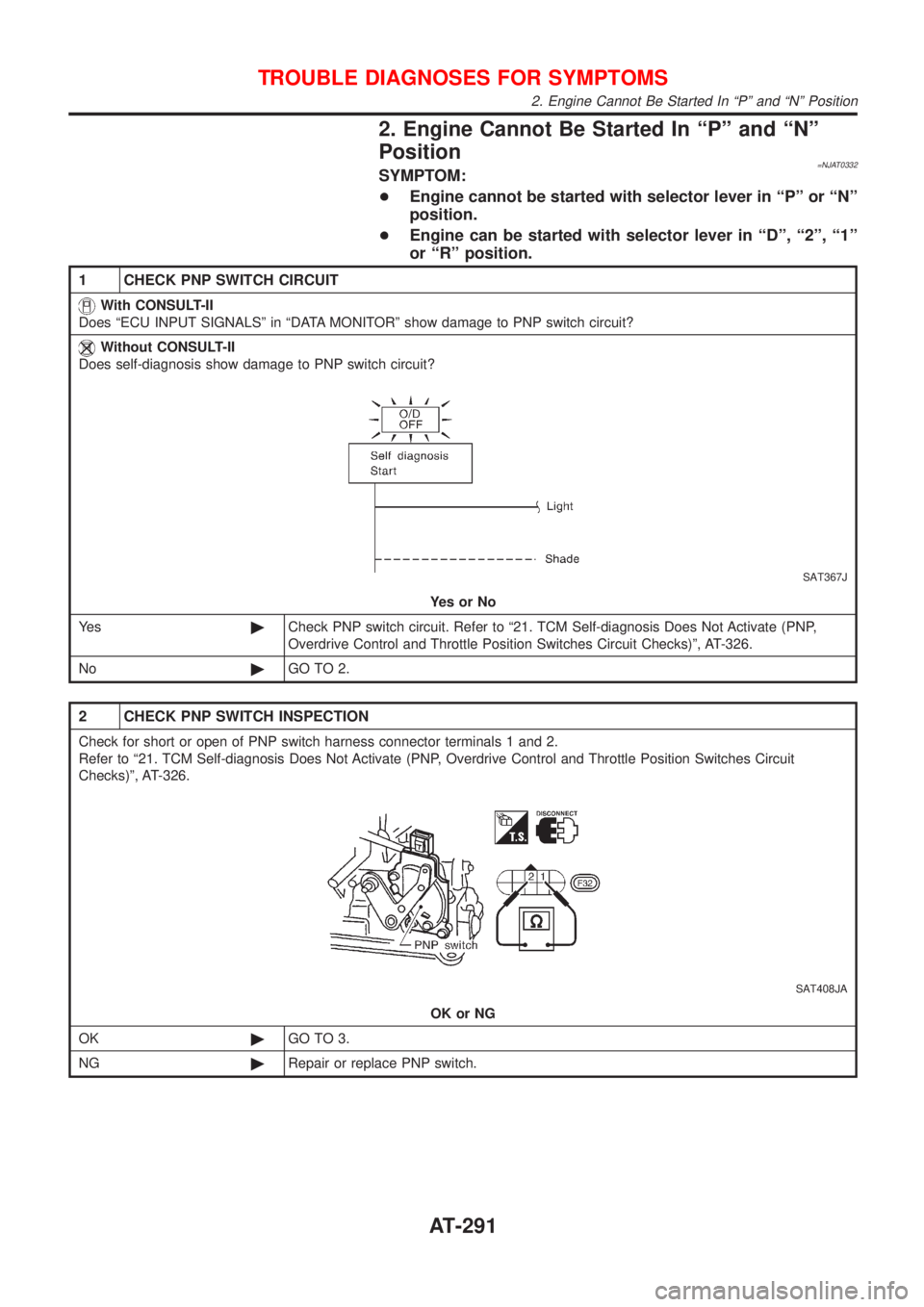
1 CHECK PNP SWITCH CIRCUIT
With CONSULT-II
Does ªECU INPUT SIGNALSº in ªDATA MONITORº show damage to PNP switch circuit?
Without CONSULT-II
Does self-diagnosis show damage to PNP switch circuit?
SAT367J
YesorNo
Ye s©Check PNP switch circuit. Refer to ª21. TCM Self-diagnosis Does Not Activate (PNP,
Overdrive Control and Throttle Position Switches Circuit Checks)º, AT-326.
No©GO TO 2.
2 CHECK PNP SWITCH INSPECTION
Check for short or open of PNP switch harness connector terminals 1 and 2.
Refer to ª21. TCM Self-diagnosis Does Not Activate (PNP, Overdrive Control and Throttle Position Switches Circuit
Checks)º, AT-326.
SAT408JA
OK or NG
OK©GO TO 3.
NG©Repair or replace PNP switch.
TROUBLE DIAGNOSES FOR SYMPTOMS
2. Engine Cannot Be Started In ªPº and ªNº Position
AT-291
Page 1479 of 2493
4. In ªNº Position, Vehicle Moves=NJAT0334SYMPTOM:
Vehicle moves forward or backward when selecting ªNº posi-
tion.
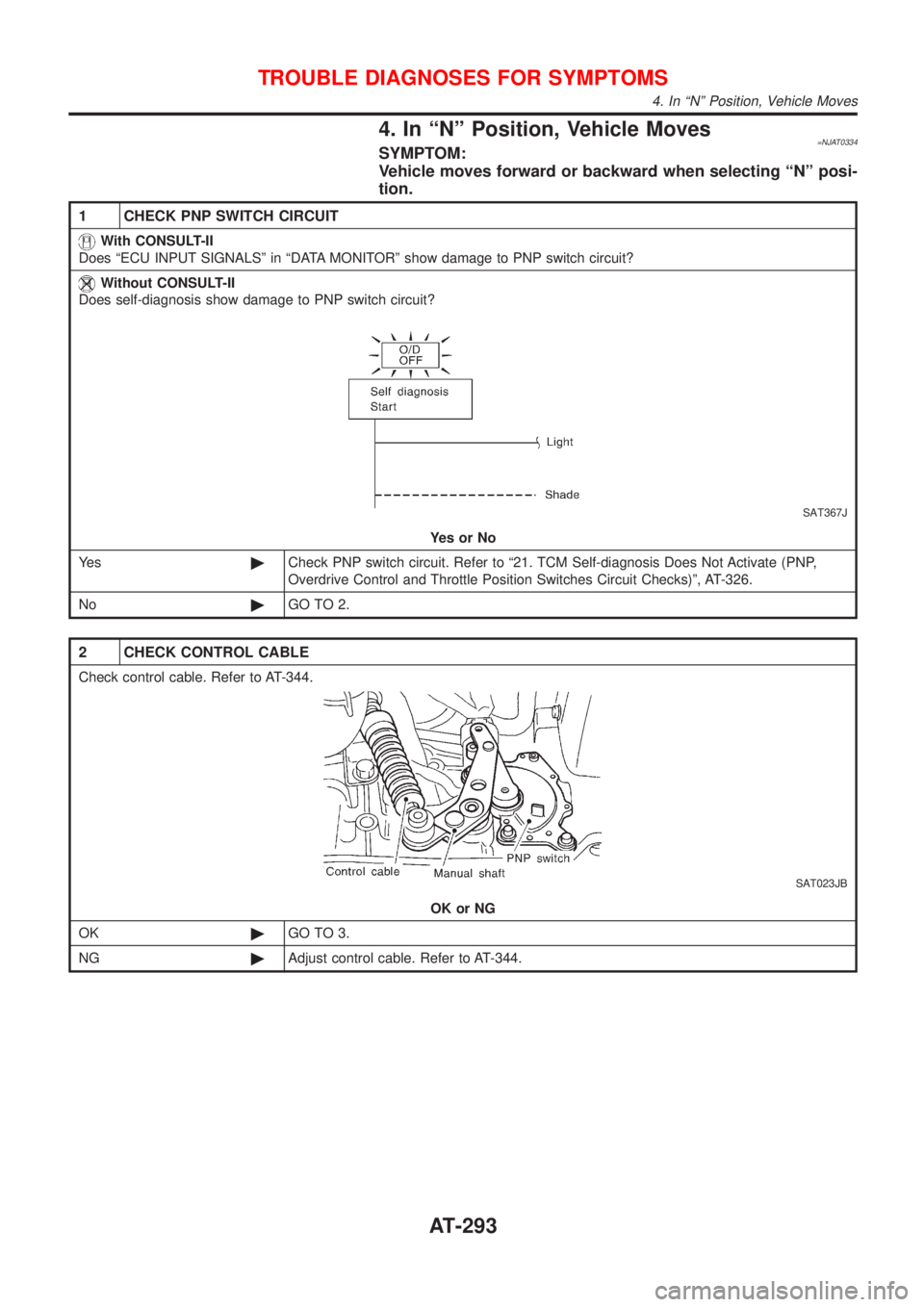
1 CHECK PNP SWITCH CIRCUIT
With CONSULT-II
Does ªECU INPUT SIGNALSº in ªDATA MONITORº show damage to PNP switch circuit?
Without CONSULT-II
Does self-diagnosis show damage to PNP switch circuit?
SAT367J
YesorNo
Ye s©Check PNP switch circuit. Refer to ª21. TCM Self-diagnosis Does Not Activate (PNP,
Overdrive Control and Throttle Position Switches Circuit Checks)º, AT-326.
No©GO TO 2.
2 CHECK CONTROL CABLE
Check control cable. Refer to AT-344.
SAT023JB
OK or NG
OK©GO TO 3.
NG©Adjust control cable. Refer to AT-344.
TROUBLE DIAGNOSES FOR SYMPTOMS
4. In ªNº Position, Vehicle Moves
AT-293
Page 1492 of 2493
9. A/T Does Not Shift: D1®D2Or Does Not
Kickdown: D
4®D2=NJAT0339SYMPTOM:
A/T does not shift from D
1to D2at the specified speed.
A/T does not shift from D
4to D2when depressing accelerator
pedal fully at the specified speed.
1 CHECK SYMPTOM
Are 7. Vehicle Does Not Creep Forward In ªDº, ª2º Or ª1º Position and 8. Vehicle Cannot Be Started From D1OK?
YesorNo
Ye s©GO TO 2.
No©Go to 7. Vehicle Does Not Creep Forward In ªDº, ª2º Or ª1º Position and 8. Vehicle Can-
not Be Started From D
1, AT-300, 303.
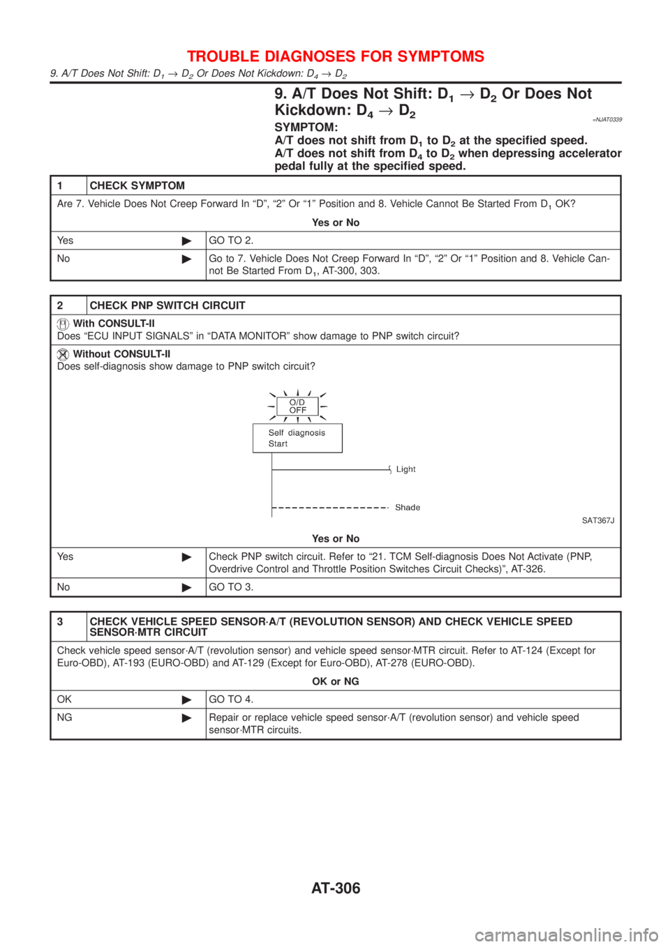
2 CHECK PNP SWITCH CIRCUIT
With CONSULT-II
Does ªECU INPUT SIGNALSº in ªDATA MONITORº show damage to PNP switch circuit?
Without CONSULT-II
Does self-diagnosis show damage to PNP switch circuit?
SAT367J
YesorNo
Ye s©Check PNP switch circuit. Refer to ª21. TCM Self-diagnosis Does Not Activate (PNP,
Overdrive Control and Throttle Position Switches Circuit Checks)º, AT-326.
No©GO TO 3.
3 CHECK VEHICLE SPEED SENSOR´A/T (REVOLUTION SENSOR) AND CHECK VEHICLE SPEED
SENSOR´MTR CIRCUIT
Check vehicle speed sensor´A/T (revolution sensor) and vehicle speed sensor´MTR circuit. Refer to AT-124 (Except for
Euro-OBD), AT-193 (EURO-OBD) and AT-129 (Except for Euro-OBD), AT-278 (EURO-OBD).
OK or NG
OK©GO TO 4.
NG©Repair or replace vehicle speed sensor´A/T (revolution sensor) and vehicle speed
sensor´MTR circuits.
TROUBLE DIAGNOSES FOR SYMPTOMS
9. A/T Does Not Shift: D1®D2Or Does Not Kickdown: D4®D2
AT-306
Page 1495 of 2493
10. A/T Does Not Shift: D2®D3=NJAT0340SYMPTOM:
A/T does not shift from D
2to D3at the specified speed.
1 CHECK SYMPTOM
Are 7. Vehicle Does Not Creep Forward In ªDº, ª2º Or ª1º Position and 8. Vehicle Cannot Be Started From D1OK?
YesorNo
Ye s©GO TO 2.
No©Go to 7. Vehicle Does Not Creep Forward In ªDº, ª2º Or ª1º Position and 8. Vehicle Can-
not Be Started From D
1, AT-300, 303.
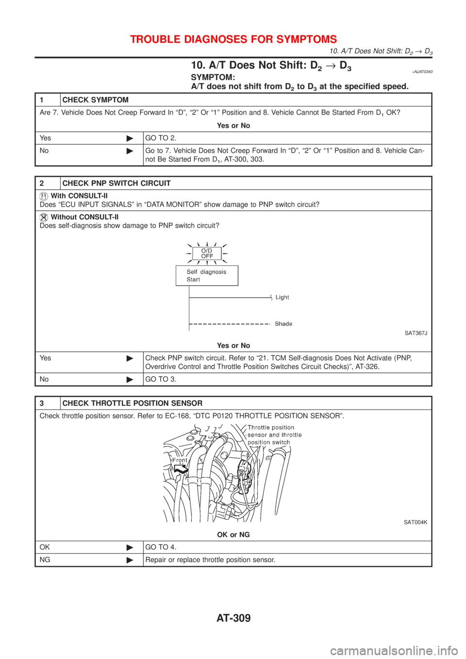
2 CHECK PNP SWITCH CIRCUIT
With CONSULT-II
Does ªECU INPUT SIGNALSº in ªDATA MONITORº show damage to PNP switch circuit?
Without CONSULT-II
Does self-diagnosis show damage to PNP switch circuit?
SAT367J
YesorNo
Ye s©Check PNP switch circuit. Refer to ª21. TCM Self-diagnosis Does Not Activate (PNP,
Overdrive Control and Throttle Position Switches Circuit Checks)º, AT-326.
No©GO TO 3.
3 CHECK THROTTLE POSITION SENSOR
Check throttle position sensor. Refer to EC-168, ªDTC P0120 THROTTLE POSITION SENSORº.
SAT004K
OK or NG
OK©GO TO 4.
NG©Repair or replace throttle position sensor.
TROUBLE DIAGNOSES FOR SYMPTOMS
10. A/T Does Not Shift: D2®D3
AT-309