ECU NISSAN ALMERA N16 2001 Electronic Workshop Manual
[x] Cancel search | Manufacturer: NISSAN, Model Year: 2001, Model line: ALMERA N16, Model: NISSAN ALMERA N16 2001Pages: 2493, PDF Size: 66.97 MB
Page 644 of 2493
SEF174Y
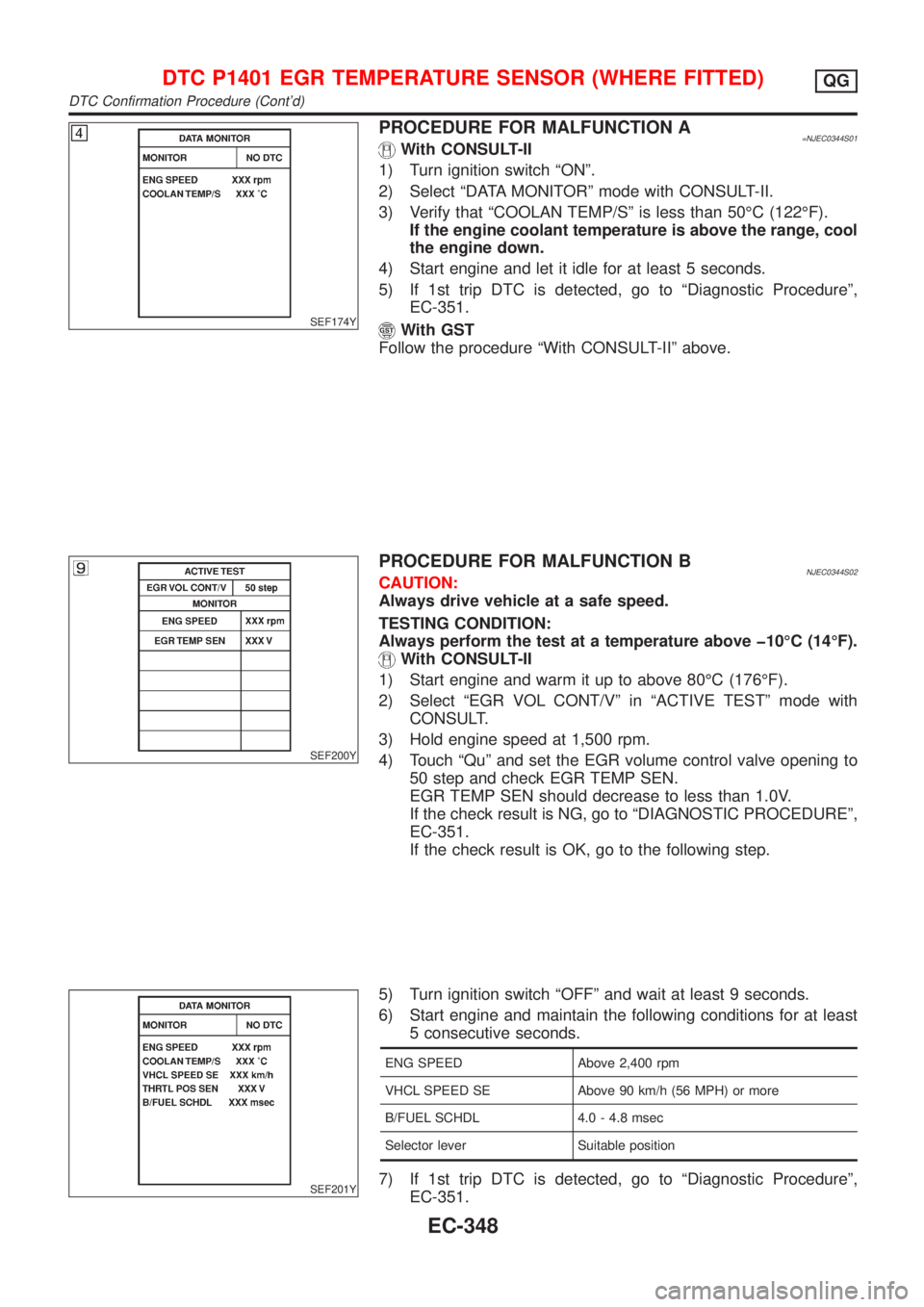
PROCEDURE FOR MALFUNCTION A=NJEC0344S01With CONSULT-II
1) Turn ignition switch ªONº.
2) Select ªDATA MONITORº mode with CONSULT-II.
3) Verify that ªCOOLAN TEMP/Sº is less than 50ÉC (122ÉF).
If the engine coolant temperature is above the range, cool
the engine down.
4) Start engine and let it idle for at least 5 seconds.
5) If 1st trip DTC is detected, go to ªDiagnostic Procedureº,
EC-351.
With GST
Follow the procedure ªWith CONSULT-IIº above.
SEF200Y
PROCEDURE FOR MALFUNCTION BNJEC0344S02CAUTION:
Always drive vehicle at a safe speed.
TESTING CONDITION:
Always perform the test at a temperature above þ10ÉC (14ÉF).
With CONSULT-II
1) Start engine and warm it up to above 80ÉC (176ÉF).
2) Select ªEGR VOL CONT/Vº in ªACTIVE TESTº mode with
CONSULT.
3) Hold engine speed at 1,500 rpm.
4) Touch ªQuº and set the EGR volume control valve opening to
50 step and check EGR TEMP SEN.
EGR TEMP SEN should decrease to less than 1.0V.
If the check result is NG, go to ªDIAGNOSTIC PROCEDUREº,
EC-351.
If the check result is OK, go to the following step.
SEF201Y
5) Turn ignition switch ªOFFº and wait at least 9 seconds.
6) Start engine and maintain the following conditions for at least
5 consecutive seconds.
ENG SPEED Above 2,400 rpm
VHCL SPEED SE Above 90 km/h (56 MPH) or more
B/FUEL SCHDL 4.0 - 4.8 msec
Selector lever Suitable position
7) If 1st trip DTC is detected, go to ªDiagnostic Procedureº,
EC-351.
DTC P1401 EGR TEMPERATURE SENSOR (WHERE FITTED)QG
DTC Confirmation Procedure (Cont'd)
EC-348
Page 645 of 2493

With GST
1) Start engine and warm it up to normal operating temperature.
2) Turn ignition switch ªOFFº and wait at least 9 seconds, then
turn ªONº.
3) Select ªMODE 1º with GST and maintain the following condi-
tions for at least 5 consecutive seconds.
Engine speed Above 2,400 rpm
Vehicle speed Above 90 km/h (56 MPH)
Selector lever 4th or 5th
4) Select ªMODE 7º with GST
5) If 1st trip DTC is detected, go to ªDiagnostic Procedureº,
EC-351.
DTC P1401 EGR TEMPERATURE SENSOR (WHERE FITTED)QG
DTC Confirmation Procedure (Cont'd)
EC-349
Page 661 of 2493
SEF213Y
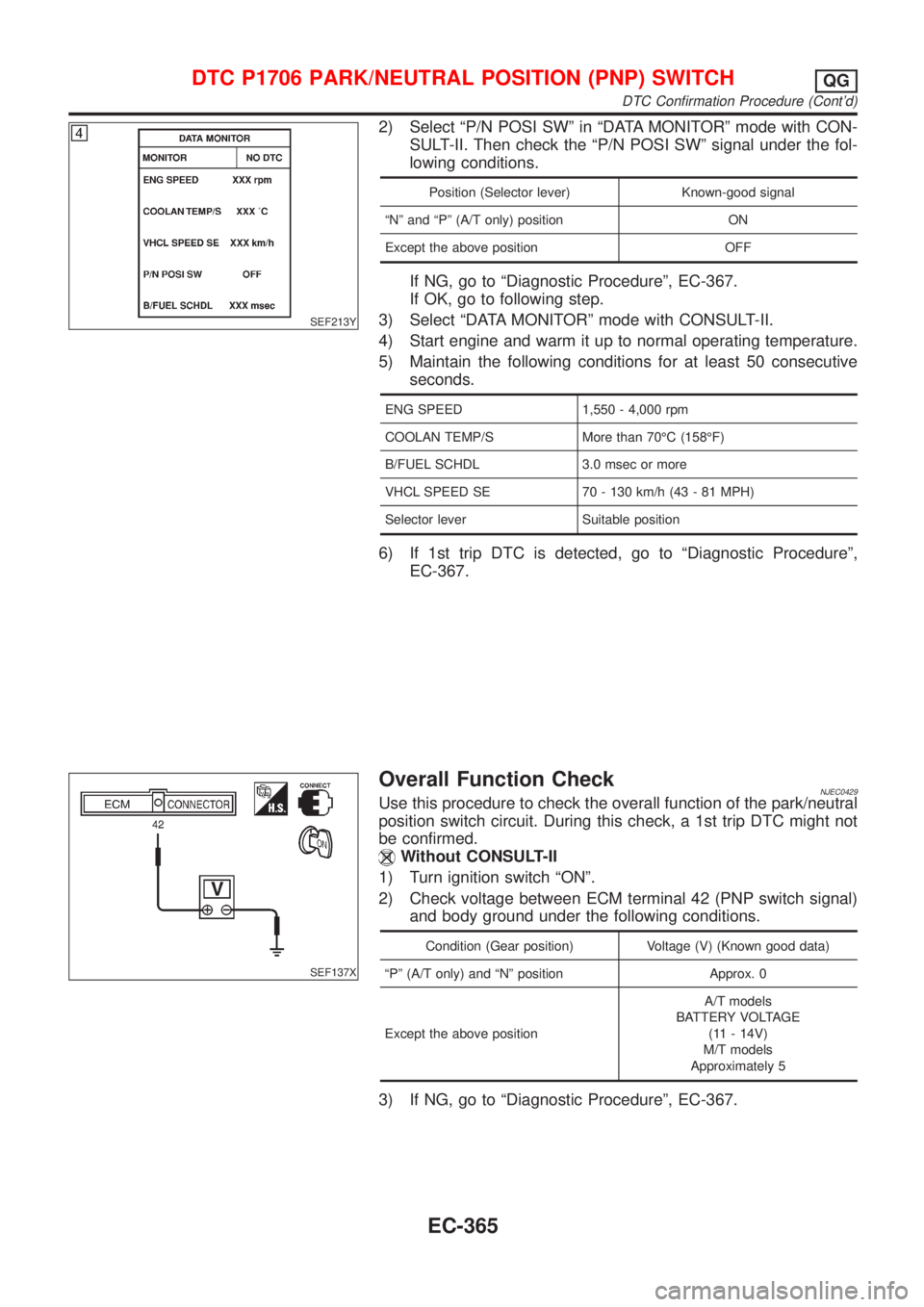
2) Select ªP/N POSI SWº in ªDATA MONITORº mode with CON-
SULT-II. Then check the ªP/N POSI SWº signal under the fol-
lowing conditions.
Position (Selector lever) Known-good signal
ªNº and ªPº (A/T only) position ON
Except the above position OFF
If NG, go to ªDiagnostic Procedureº, EC-367.
If OK, go to following step.
3) Select ªDATA MONITORº mode with CONSULT-II.
4) Start engine and warm it up to normal operating temperature.
5) Maintain the following conditions for at least 50 consecutive
seconds.
ENG SPEED 1,550 - 4,000 rpm
COOLAN TEMP/S More than 70ÉC (158ÉF)
B/FUEL SCHDL 3.0 msec or more
VHCL SPEED SE 70 - 130 km/h (43 - 81 MPH)
Selector lever Suitable position
6) If 1st trip DTC is detected, go to ªDiagnostic Procedureº,
EC-367.
SEF137X
Overall Function CheckNJEC0429Use this procedure to check the overall function of the park/neutral
position switch circuit. During this check, a 1st trip DTC might not
be confirmed.
Without CONSULT-II
1) Turn ignition switch ªONº.
2) Check voltage between ECM terminal 42 (PNP switch signal)
and body ground under the following conditions.
Condition (Gear position) Voltage (V) (Known good data)
ªPº (A/T only) and ªNº position Approx. 0
Except the above positionA/T models
BATTERY VOLTAGE
(11 - 14V)
M/T models
Approximately 5
3) If NG, go to ªDiagnostic Procedureº, EC-367.
DTC P1706 PARK/NEUTRAL POSITION (PNP) SWITCHQG
DTC Confirmation Procedure (Cont'd)
EC-365
Page 681 of 2493
Diagnostic ProcedureNJEC1238
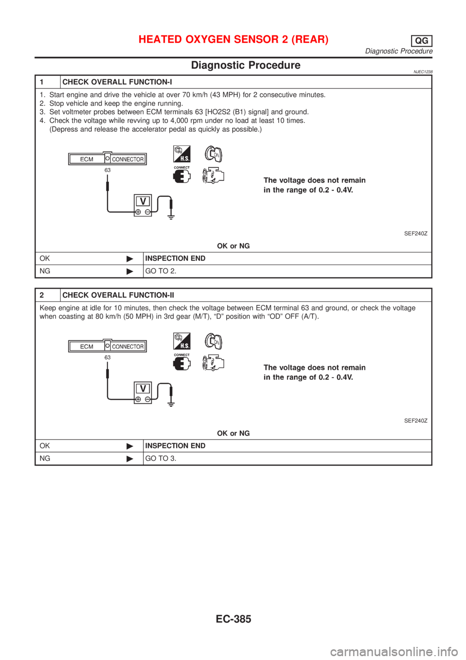
1 CHECK OVERALL FUNCTION-I
1. Start engine and drive the vehicle at over 70 km/h (43 MPH) for 2 consecutive minutes.
2. Stop vehicle and keep the engine running.
3. Set voltmeter probes between ECM terminals 63 [HO2S2 (B1) signal] and ground.
4. Check the voltage while revving up to 4,000 rpm under no load at least 10 times.
(Depress and release the accelerator pedal as quickly as possible.)
SEF240Z
OK or NG
OK©INSPECTION END
NG©GO TO 2.
2 CHECK OVERALL FUNCTION-II
Keep engine at idle for 10 minutes, then check the voltage between ECM terminal 63 and ground, or check the voltage
when coasting at 80 km/h (50 MPH) in 3rd gear (M/T), ªDº position with ªODº OFF (A/T).
SEF240Z
OK or NG
OK©INSPECTION END
NG©GO TO 3.
HEATED OXYGEN SENSOR 2 (REAR)QG
Diagnostic Procedure
EC-385
Page 683 of 2493
6 CHECK GROUND CIRCUIT
1. Check harness continuity between heated oxygen sensor 2 (rear) harness connector terminal 4 and body ground.
Refer to wiring diagram.
Continuity should exist.
2. Also check harness for short to ground and short to power.
OK or NG
OK©GO TO 7.
NG©Repair open circuit or short to ground or short to power in harness or connectors.
7 CHECK HEATED OXYGEN SENSOR 2 (REAR)
Refer to ªComponent Inspectionº, EC-387.
OK or NG
OK©GO TO 8.
NG©Replace heated oxygen sensor 2 (rear).
8 CHECK INTERMITTENT INCIDENT
Perform ªTROUBLE DIAGNOSIS FOR INTERMITTENT INCIDENTº, EC-144.
©INSPECTION END
SEF662Y
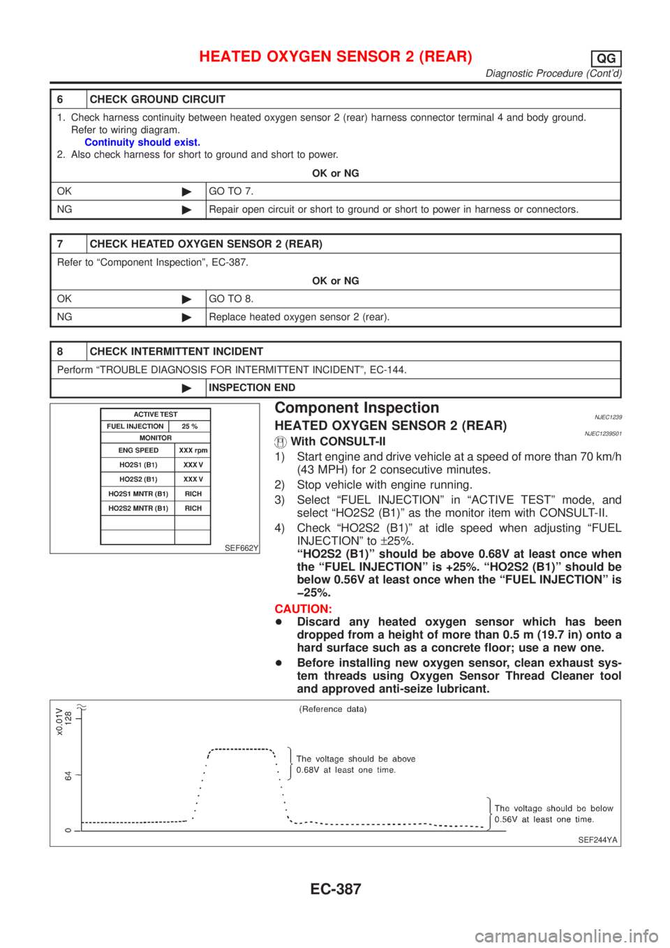
Component InspectionNJEC1239HEATED OXYGEN SENSOR 2 (REAR)NJEC1239S01With CONSULT-II
1) Start engine and drive vehicle at a speed of more than 70 km/h
(43 MPH) for 2 consecutive minutes.
2) Stop vehicle with engine running.
3) Select ªFUEL INJECTIONº in ªACTIVE TESTº mode, and
select ªHO2S2 (B1)º as the monitor item with CONSULT-II.
4) Check ªHO2S2 (B1)º at idle speed when adjusting ªFUEL
INJECTIONº to±25%.
ªHO2S2 (B1)º should be above 0.68V at least once when
the ªFUEL INJECTIONº is +25%. ªHO2S2 (B1)º should be
below 0.56V at least once when the ªFUEL INJECTIONº is
þ25%.
CAUTION:
+Discard any heated oxygen sensor which has been
dropped from a height of more than 0.5 m (19.7 in) onto a
hard surface such as a concrete floor; use a new one.
+Before installing new oxygen sensor, clean exhaust sys-
tem threads using Oxygen Sensor Thread Cleaner tool
and approved anti-seize lubricant.
SEF244YA
HEATED OXYGEN SENSOR 2 (REAR)QG
Diagnostic Procedure (Cont'd)
EC-387
Page 684 of 2493
SEF032X
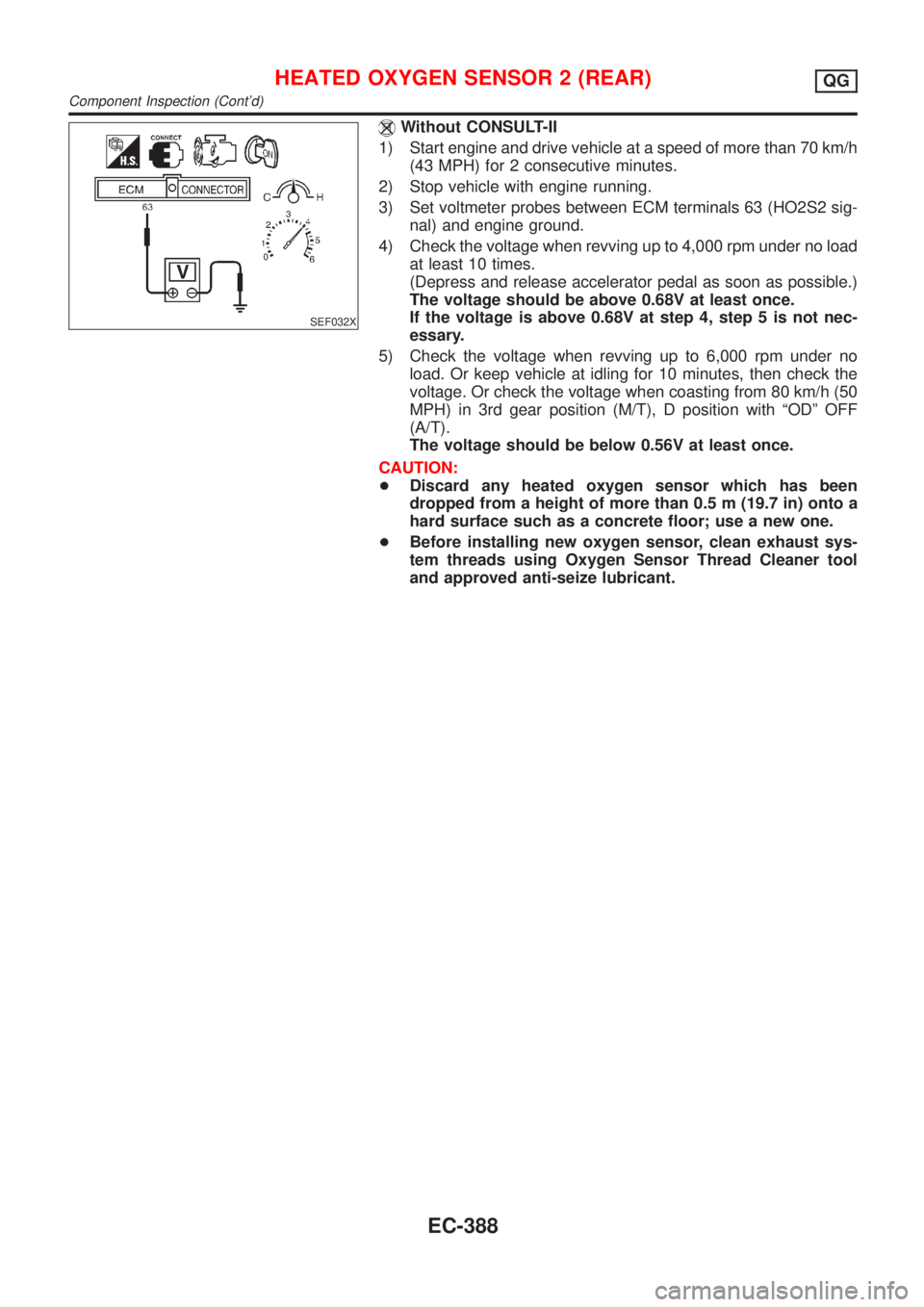
Without CONSULT-II
1) Start engine and drive vehicle at a speed of more than 70 km/h
(43 MPH) for 2 consecutive minutes.
2) Stop vehicle with engine running.
3) Set voltmeter probes between ECM terminals 63 (HO2S2 sig-
nal) and engine ground.
4) Check the voltage when revving up to 4,000 rpm under no load
at least 10 times.
(Depress and release accelerator pedal as soon as possible.)
The voltage should be above 0.68V at least once.
If the voltage is above 0.68V at step 4, step 5 is not nec-
essary.
5) Check the voltage when revving up to 6,000 rpm under no
load. Or keep vehicle at idling for 10 minutes, then check the
voltage. Or check the voltage when coasting from 80 km/h (50
MPH) in 3rd gear position (M/T), D position with ªODº OFF
(A/T).
The voltage should be below 0.56V at least once.
CAUTION:
+Discard any heated oxygen sensor which has been
dropped from a height of more than 0.5 m (19.7 in) onto a
hard surface such as a concrete floor; use a new one.
+Before installing new oxygen sensor, clean exhaust sys-
tem threads using Oxygen Sensor Thread Cleaner tool
and approved anti-seize lubricant.
HEATED OXYGEN SENSOR 2 (REAR)QG
Component Inspection (Cont'd)
EC-388
Page 687 of 2493
Diagnostic ProcedureNJEC1246
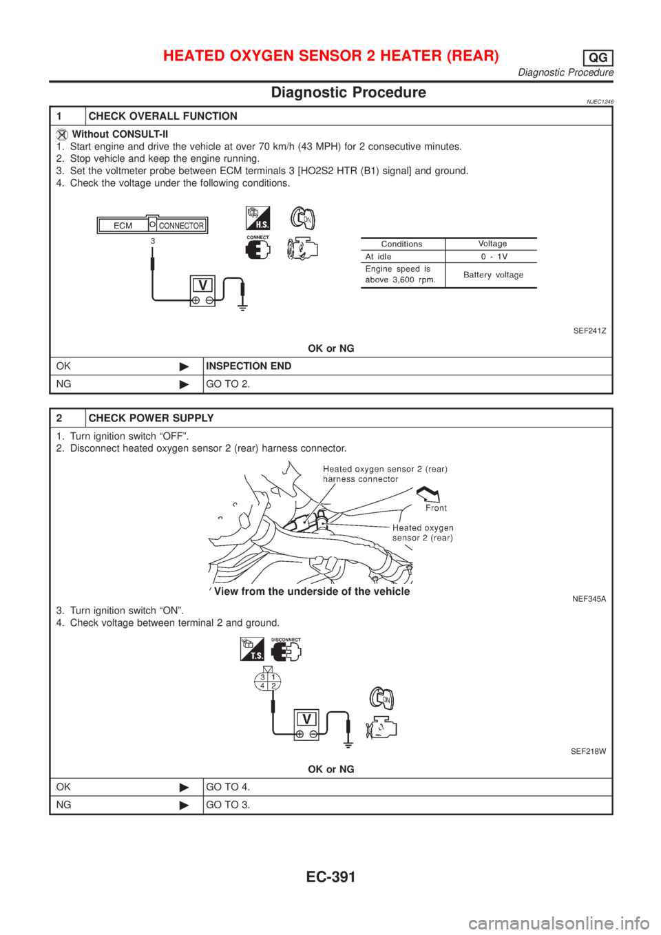
1 CHECK OVERALL FUNCTION
Without CONSULT-II
1. Start engine and drive the vehicle at over 70 km/h (43 MPH) for 2 consecutive minutes.
2. Stop vehicle and keep the engine running.
3. Set the voltmeter probe between ECM terminals 3 [HO2S2 HTR (B1) signal] and ground.
4. Check the voltage under the following conditions.
SEF241Z
OK or NG
OK©INSPECTION END
NG©GO TO 2.
2 CHECK POWER SUPPLY
1. Turn ignition switch ªOFFº.
2. Disconnect heated oxygen sensor 2 (rear) harness connector.
NEF345A
3. Turn ignition switch ªONº.
4. Check voltage between terminal 2 and ground.
SEF218W
OK or NG
OK©GO TO 4.
NG©GO TO 3.
HEATED OXYGEN SENSOR 2 HEATER (REAR)QG
Diagnostic Procedure
EC-391
Page 815 of 2493
JEF369Y
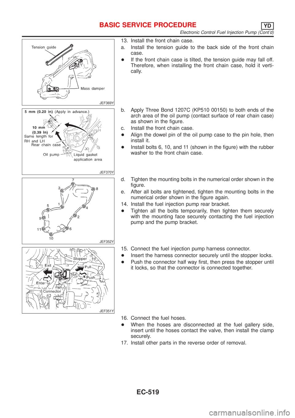
13. Install the front chain case.
a. Install the tension guide to the back side of the front chain
case.
+If the front chain case is tilted, the tension guide may fall off.
Therefore, when installing the front chain case, hold it verti-
cally.
JEF370Y
b. Apply Three Bond 1207C (KP510 00150) to both ends of the
arch area of the oil pump (contact surface of rear chain case)
as shown in the figure.
c. Install the front chain case.
+Align the dowel pin of the oil pump case to the pin hole, then
install it.
+Install bolts 6, 10, and 11 (shown in the figure) with the rubber
washer to the front chain case.
JEF352Y
d. Tighten the mounting bolts in the numerical order shown in the
figure.
e. After all bolts are tightened, tighten the mounting bolts in the
numerical order shown in the figure again.
14. Install the fuel injection pump rear bracket.
+Tighten all the bolts temporarily, then tighten them securely
with the mounting face securely contacting the fuel injection
pump and the pump bracket.
JEF351Y
15. Connect the fuel injection pump harness connector.
+Insert the harness connector securely until the stopper locks.
+Push the connector half way first, then press the stopper until
it locks, so that the connector is connected together.
16. Connect the fuel hoses.
+When the hoses are disconnected at the fuel gallery side,
insert until the hoses contact the valve, then install the clamp
securely.
17. Install other parts in the reverse order of removal.
BASIC SERVICE PROCEDUREYD
Electronic Control Fuel Injection Pump (Cont'd)
EC-519
Page 822 of 2493
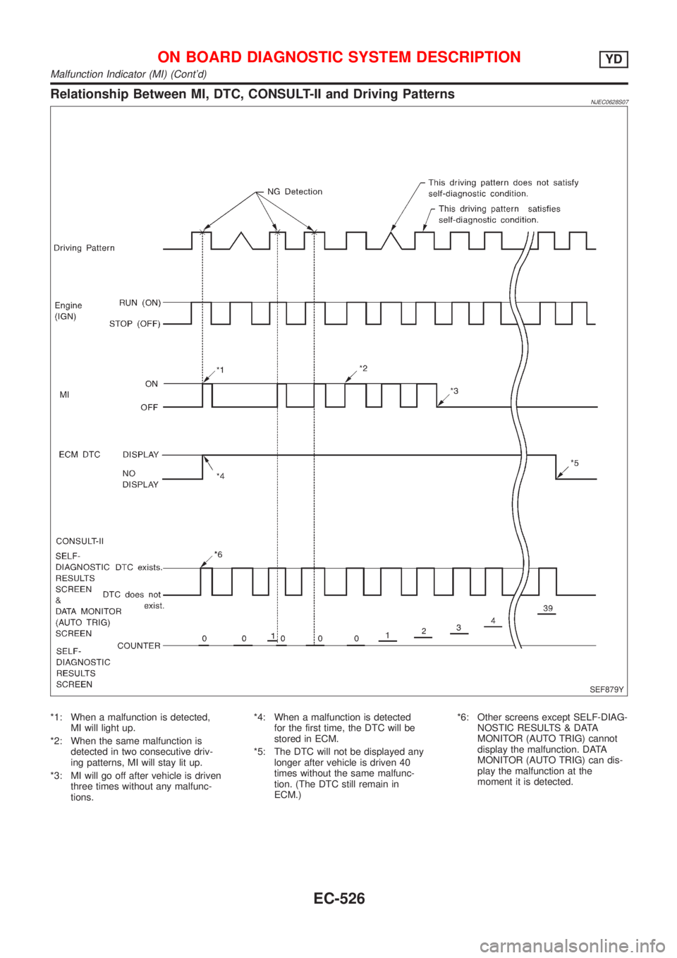
Relationship Between MI, DTC, CONSULT-II and Driving PatternsNJEC0628S07
SEF879Y
*1: When a malfunction is detected,
MI will light up.
*2: When the same malfunction is
detected in two consecutive driv-
ing patterns, MI will stay lit up.
*3: MI will go off after vehicle is driven
three times without any malfunc-
tions.*4: When a malfunction is detected
for the first time, the DTC will be
stored in ECM.
*5: The DTC will not be displayed any
longer after vehicle is driven 40
times without the same malfunc-
tion. (The DTC still remain in
ECM.)*6: Other screens except SELF-DIAG-
NOSTIC RESULTS & DATA
MONITOR (AUTO TRIG) cannot
display the malfunction. DATA
MONITOR (AUTO TRIG) can dis-
play the malfunction at the
moment it is detected.
ON BOARD DIAGNOSTIC SYSTEM DESCRIPTIONYD
Malfunction Indicator (MI) (Cont'd)
EC-526
Page 855 of 2493
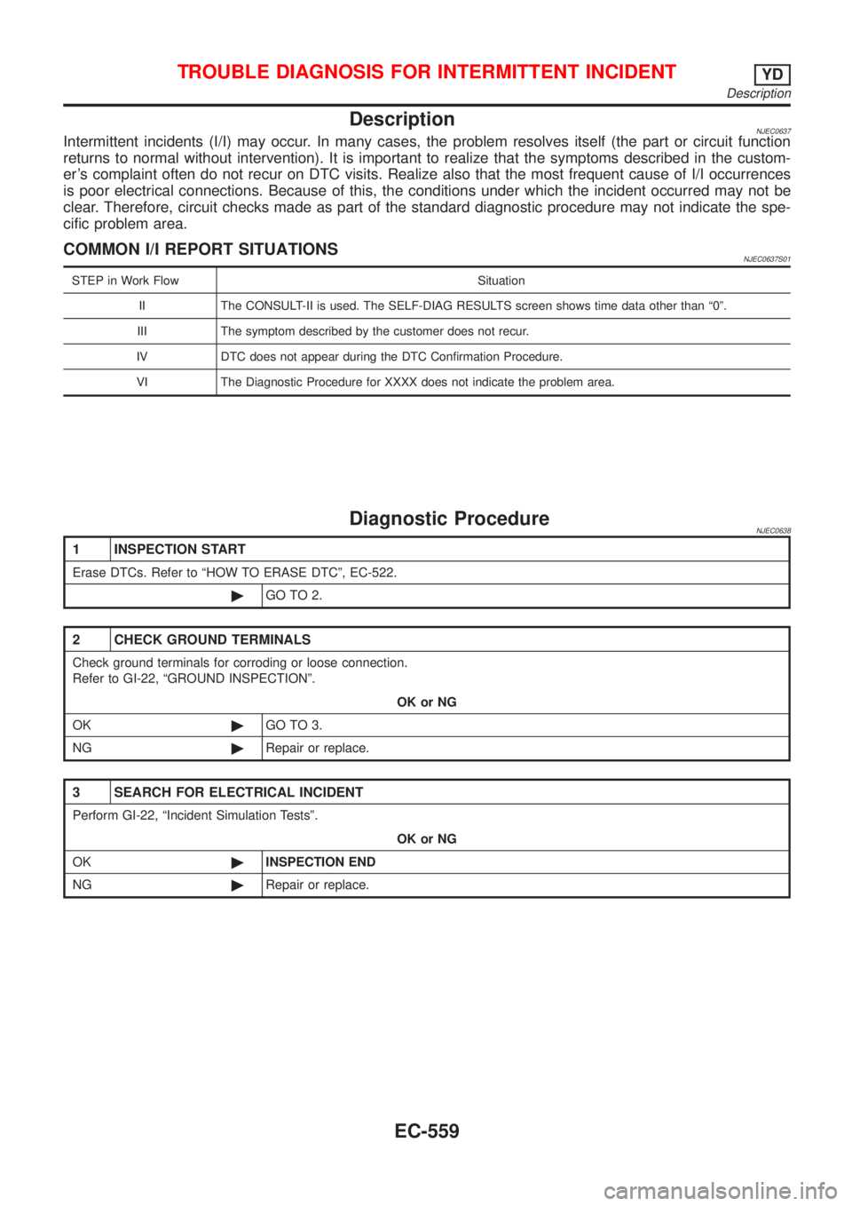
DescriptionNJEC0637Intermittent incidents (I/I) may occur. In many cases, the problem resolves itself (the part or circuit function
returns to normal without intervention). It is important to realize that the symptoms described in the custom-
er's complaint often do not recur on DTC visits. Realize also that the most frequent cause of I/I occurrences
is poor electrical connections. Because of this, the conditions under which the incident occurred may not be
clear. Therefore, circuit checks made as part of the standard diagnostic procedure may not indicate the spe-
cific problem area.
COMMON I/I REPORT SITUATIONSNJEC0637S01
STEP in Work Flow Situation
II The CONSULT-II is used. The SELF-DIAG RESULTS screen shows time data other than ª0º.
III The symptom described by the customer does not recur.
IV DTC does not appear during the DTC Confirmation Procedure.
VI The Diagnostic Procedure for XXXX does not indicate the problem area.
Diagnostic ProcedureNJEC0638
1 INSPECTION START
Erase DTCs. Refer to ªHOW TO ERASE DTCº, EC-522.
©GO TO 2.
2 CHECK GROUND TERMINALS
Check ground terminals for corroding or loose connection.
Refer to GI-22, ªGROUND INSPECTIONº.
OK or NG
OK©GO TO 3.
NG©Repair or replace.
3 SEARCH FOR ELECTRICAL INCIDENT
Perform GI-22, ªIncident Simulation Testsº.
OK or NG
OK©INSPECTION END
NG©Repair or replace.
TROUBLE DIAGNOSIS FOR INTERMITTENT INCIDENTYD
Description
EC-559