lug NISSAN ALMERA N16 2001 Electronic Owners Manual
[x] Cancel search | Manufacturer: NISSAN, Model Year: 2001, Model line: ALMERA N16, Model: NISSAN ALMERA N16 2001Pages: 2493, PDF Size: 66.97 MB
Page 1268 of 2493

SAT561J
Line Pressure TestNJAT0027LINE PRESSURE TEST PORTSNJAT0027S01Location of line pressure test ports are shown in the illustration.
+Always replace pressure plugs as they are self-sealing
bolts.
SAT647B
LINE PRESSURE TEST PROCEDURENJAT0027S021. Check A/T fluid and engine oil levels. If necessary, add fluid or
oil.
2. Drive vehicle for approx. 10 minutes or until engine oil and ATF
reach operating temperature.
ATF operating temperature:
50 - 80ÉC (122 - 176ÉF)
UAT008
3. Install pressure gauge to corresponding line pressure port.
UAT008
4. Set parking brake and block wheels.
+Continue to depress brake pedal fully while line pressure
test is being performed at stall speed.
SAT493G
5. Start engine and measure line pressure at idle and stall speed.
+When measuring line pressure at stall speed, follow the
stall test procedure.
Line pressure: Refer to SDS, AT-450.
TROUBLE DIAGNOSIS Ð BASIC INSPECTION
Line Pressure Test
AT-82
Page 1269 of 2493

JUDGEMENT OF LINE PRESSURE TESTNJAT0027S03
Judgement Suspected parts
At idleLine pressure is low in all positions.+Oil pump wear
+Control piston damage
+Pressure regulator valve or plug sticking
+Spring for pressure regulator valve damaged
+Fluid pressure leakage between oil strainer and pressure regulator valve
+Clogged strainer
Line pressure is low in particular
position.+Fluid pressure leakage between manual valve and particular clutch
+For example, line pressure is:
þ Low in ªRº and ª1º positions, but
þ Normal in ªDº and ª2º positions.
Therefore, fluid leakage exists at or around low and reverse brake circuit.
Refer to ªCLUTCH AND BAND CHARTº, AT-21.
Line pressure is high.+Maladjustment of throttle position sensor
+A/T fluid temperature sensor damaged
+Line pressure solenoid valve sticking
+Short circuit of line pressure solenoid valve circuit
+Pressure modifier valve sticking
+Pressure regulator valve or plug sticking
+Open in dropping resistor circuit
At stall
speedLine pressure is low.+Maladjustment of throttle position sensor
+Line pressure solenoid valve sticking
+Short circuit of line pressure solenoid valve circuit
+Pressure regulator valve or plug sticking
+Pressure modifier valve sticking
+Pilot valve sticking
SAT786A
Road TestNJAT0028DESCRIPTIONNJAT0028S01+The purpose of the test is to determine overall performance of
A/T and analyze causes of problems.
+The road test consists of the following three parts:
1. Check before engine is started
2. Check at idle
3. Cruise test
SAT496G
+Before road test, familiarize yourself with all test procedures
and items to check.
+Conduct tests on all items until specified symptom is found.
Troubleshoot items which check out No Good after road test.
Refer to the following items.
ON BOARD DIAGNOSITC
SYSTEM DESCRIPTIONTROUBLE DIAGNOSES FOR
SYMPTOMS
General and
Except for
Euro-OBDAT-37 - AT-47 AT-286 and AT-288 - AT-326
TROUBLE DIAGNOSIS Ð BASIC INSPECTION
Line Pressure Test (Cont'd)
AT-83
Page 1393 of 2493

2 CHECK CONTROL VALVE
1. Disassemble control valve assembly. Refer to ªControl Valve Assemblyº, AT-375.
2. Check to ensure that:
+Valve, sleeve and plug slide along valve bore under their own weight.
+Valve, sleeve and plug are free from burrs, dents and scratches.
+Control valve springs are free from damage, deformation and fatigue.
+Hydraulic line is free from obstacles.
SAT367H
OK or NG
OK©GO TO 3.
NG©Repair control valve assembly.
3 CHECK DTC
Perform Diagnostic Trouble Code (DTC) confirmation procedure, AT-203.
OK or NG
OK©INSPECTION END
NG©Check control valve again. Repair or replace control valve assembly.
SAT050KA
Component InspectionNJAT0282SHIFT SOLENOID VALVE A AND BNJAT0282S01+For removal, refer to AT-343.
Resistance CheckNJAT0282S0101+Check resistance between two terminals.
Solenoid valve Terminal No.Resistance
(Approx.)
Shift solenoid
valve A2
Ground20-30W
Shift solenoid
valve B1 5-20W
DTC P0731 A/T 1ST GEAR FUNCTIONEURO-OBD
Diagnostic Procedure (Cont'd)
AT-207
Page 1399 of 2493

Diagnostic ProcedureNJAT0285
1 CHECK SHIFT SOLENOID VALVE
1. Remove control valve assembly. Refer to AT-343.
2. Check shift solenoid valve operation.
+Shift solenoid valve B
Refer to ªComponent Inspectionº, AT-214.
SAT884JB
OK or NG
OK©GO TO 2.
NG©Repair or replace shift solenoid valve assembly.
2 CHECK CONTROL VALVE
1. Disassemble control valve assembly. Refer to ªControl Valve Assemblyº, AT-375.
2. Check to ensure that:
+Valve, sleeve and plug slide along valve bore under their own weight.
+Valve, sleeve and plug are free from burrs, dents and scratches.
+Control valve springs are free from damage, deformation and fatigue.
+Hydraulic line is free from obstacles.
SAT367H
OK or NG
OK©GO TO 3.
NG©Repair control valve assembly.
DTC P0732 A/T 2ND GEAR FUNCTIONEURO-OBD
Diagnostic Procedure
AT-213
Page 1405 of 2493

Diagnostic ProcedureNJAT0289
1 CHECK SHIFT SOLENOID VALVE
1. Remove control valve assembly. Refer to AT-343.
2. Check shift solenoid valve operation.
+Shift solenoid valve A
Refer to ªComponent Inspectionº below.
SAT886JA
OK or NG
OK©GO TO 2.
NG©Repair or replace shift solenoid valve assembly.
2 CHECK CONTROL VALVE
1. Disassemble control valve assembly. Refer to ªControl Valve Assemblyº, AT-375.
2. Check to ensure that:
+Valve, sleeve and plug slide along valve bore under their own weight.
+Valve, sleeve and plug are free from burrs, dents and scratches.
+Control valve springs are free from damage, deformation and fatigue.
+Hydraulic line is free from obstacles.
SAT367H
OK or NG
OK©GO TO 3.
NG©Repair control valve assembly.
DTC P0733 A/T 3RD GEAR FUNCTIONEURO-OBD
Diagnostic Procedure
AT-219
Page 1413 of 2493

3 CHECK SOLENOID VALVES
1. Remove control valve assembly.
Refer to AT-343.
2. Refer to ªComponent Inspectionº, AT-230.
SAT847JB
OK or NG
OK©GO TO 4.
NG©Replace solenoid valve assembly.
4 CHECK CONTROL VALVE
1. Disassemble control valve assembly.
Refer to AT-375.
2. Check to ensure that:
+Valve, sleeve and plug slide along valve bore under their own weight.
+Valve, sleeve and plug are free from burrs, dents and scratches.
+Control valve springs are free from damage, deformation and fatigue.
+Hydraulic line is free from obstacles.
SAT367H
OK or NG
OK©GO TO 5.
NG©Repair control valve.
DTC P0734 A/T 4TH GEAR FUNCTIONEURO-OBD
Diagnostic Procedure (Cont'd)
AT-227
Page 1540 of 2493
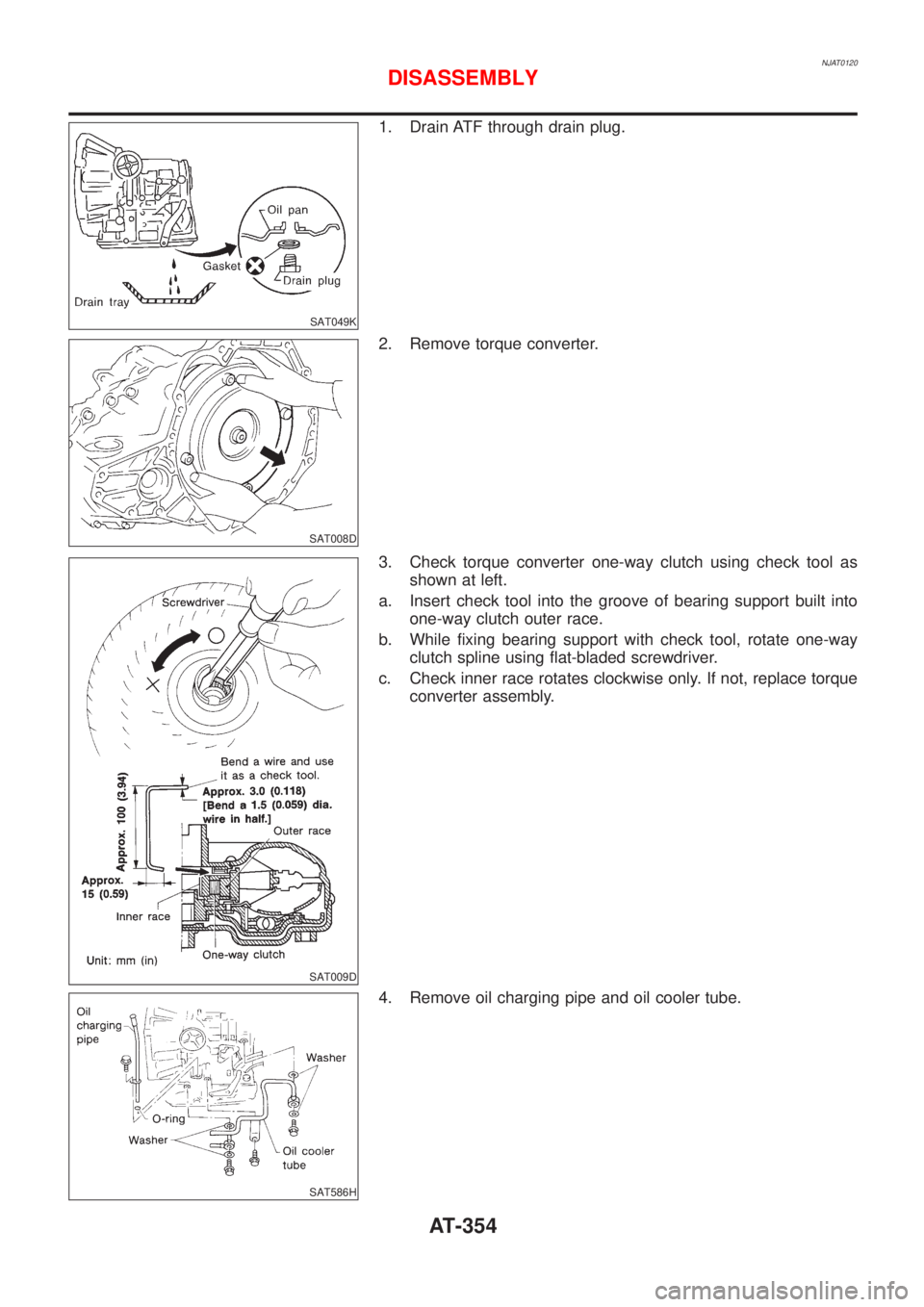
NJAT0120
SAT049K
1. Drain ATF through drain plug.
SAT008D
2. Remove torque converter.
SAT009D
3. Check torque converter one-way clutch using check tool as
shown at left.
a. Insert check tool into the groove of bearing support built into
one-way clutch outer race.
b. While fixing bearing support with check tool, rotate one-way
clutch spline using flat-bladed screwdriver.
c. Check inner race rotates clockwise only. If not, replace torque
converter assembly.
SAT586H
4. Remove oil charging pipe and oil cooler tube.
DISASSEMBLY
AT-354
Page 1570 of 2493
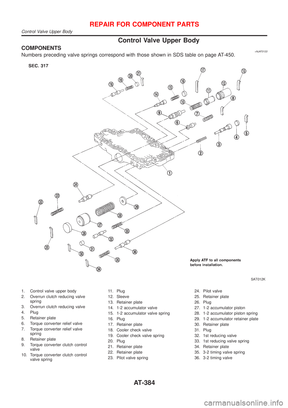
Control Valve Upper Body
COMPONENTS=NJAT0133Numbers preceding valve springs correspond with those shown in SDS table on page AT-450.
SAT012K
1. Control valve upper body
2. Overrun clutch reducing valve
spring
3. Overrun clutch reducing valve
4. Plug
5. Retainer plate
6. Torque converter relief valve
7. Torque converter relief valve
spring
8. Retainer plate
9. Torque converter clutch control
valve
10. Torque converter clutch control
valve spring11. Plug
12. Sleeve
13. Retainer plate
14. 1-2 accumulator valve
15. 1-2 accumulator valve spring
16. Plug
17. Retainer plate
18. Cooler check valve
19. Cooler check valve spring
20. Plug
21. Retainer plate
22. Retainer plate
23. Pilot valve spring24. Pilot valve
25. Retainer plate
26. Plug
27. 1-2 accumulator piston
28. 1-2 accumulator piston spring
29. 1-2 accumulator retainer plate
30. Retainer plate
31. Plug
32. 1st reducing valve
33. 1st reducing valve spring
34. Retainer plate
35. 3-2 timing valve spring
36. 3-2 timing valve
REPAIR FOR COMPONENT PARTS
Control Valve Upper Body
AT-384
Page 1571 of 2493

SAT321G
DISASSEMBLYNJAT01341. Remove valves at retainer plates.
+Do not use a magnetic ªhandº.
SAT135D
a. Use a screwdriver to remove retainer plates.
SAT136D
b. Remove retainer plates while holding spring, plugs or sleeves.
+Remove plugs slowly to prevent internal parts from jump-
ing out.
SAT137D
c. Place mating surface of valve body face down, and remove
internal parts.
+If a valve is hard to remove, place valve body face down
and lightly tap it with a soft hammer.
+Be careful not to drop or damage valves and sleeves.
SAT138D
INSPECTIONNJAT0135Valve SpringNJAT0135S01+Measure free length and outer diameter of each valve spring.
Also check for damage or deformation.
Inspection standard:
Refer to SDS, AT-450.
+Replace valve springs if deformed or fatigued.
Control ValvesNJAT0135S02+Check sliding surfaces of valves, sleeves and plugs.
REPAIR FOR COMPONENT PARTS
Control Valve Upper Body (Cont'd)
AT-385
Page 1572 of 2493

SAT139D
ASSEMBLYNJAT0136+Lay control valve body down when installing valves. Do
not stand the control valve body upright.
SAT140DA
1. Lubricate the control valve body and all valves with ATF. Install
control valves by sliding them carefully into their bores.
+Be careful not to scratch or damage valve body.
SAT141D
+Wrap a small screwdriver with vinyl tape and use it to insert the
valves into their proper positions.
SAT142DA
1-2 Accumulator ValveNJAT0136S01+Install 1-2 accumulator valve. Align 1-2 accumulator retainer
plate from opposite side of control valve body.
+Install return spring, 1-2 accumulator piston and plug.
SAT143D
1. Install retainer plates.
+Install retainer plate while pushing plug or return spring.
REPAIR FOR COMPONENT PARTS
Control Valve Upper Body (Cont'd)
AT-386