lug NISSAN ALMERA N16 2001 Electronic Repair Manual
[x] Cancel search | Manufacturer: NISSAN, Model Year: 2001, Model line: ALMERA N16, Model: NISSAN ALMERA N16 2001Pages: 2493, PDF Size: 66.97 MB
Page 1928 of 2493

3-DOOR HATCHBACKNJBT0013S02CAUTION:
+Wrap the tip of flat-bladed screwdriver with a cloth when removing metal clips from garnishes.
1. Remove front and rear seats. Refer to ªFRONT SEATº and ªREAR SEATº for details, BT-56 and BT-59.
2. Remove front and rear seat belts. Refer to RS-9 and RS-15, ªFront Seat Beltº and ªRear Seat Beltº for
details.
3. Remove outer kicking plates.
4. Remove inner kicking plates.
5. Remove dash side finishers.
6. Remove body side welts.
7. Remove front pillar garnishes.
8. Remove rear parcel shelf side finish.
9. Remove rear wheelhouse finish.
10. Remove rear side finish.
11. Remove rear pillar garnish.
12. Remove luggage room rear plate.
13. Remove luggage room rear finish.
14. Remove luggage room rear side lower finish.
15. Remove front and rear room carpet.
16. Remove luggage room carpet.
NBT065
SIDE AND FLOOR TRIM
Removal and Installation (Cont'd)
BT-34
Page 1930 of 2493

5-DOOR HATCHBACKNJBT0013S03CAUTION:
+Wrap the tip of flat-bladed screwdriver with a cloth when removing metal clips from garnishes.
1. Remove front and rear seats. Refer to ªFRONT SEATº and ªREAR SEATº for details, BT-56 and BT-59.
2. Remove front and rear seat belts. Refer to RS-7 and RS-15, ªFront Seat Beltº and ªRear Seat Beltº for
details.
3. Remove front and rear outer kicking plates.
4. Remove front and rear inner kicking plates.
5. Remove dash side finishers.
6. Remove front and rear body side welts.
7. Remove front pillar garnishes.
8. Remove center pillar lower garnishes.
9. Remove center pillar upper garnishes.
10. Remove rear parcel shelf side finish.
11. Remove rear pillar garnish.
12. Remove rear wheelhouse finish.
13. Remove luggage room rear plate.
14. Remove luggage room rear finish.
15. Remove luggage room rear side lower finish.
16. Remove front and rear room carpet.
17. Remove luggage room carpet.
SIDE AND FLOOR TRIM
Removal and Installation (Cont'd)
BT-36
Page 1960 of 2493
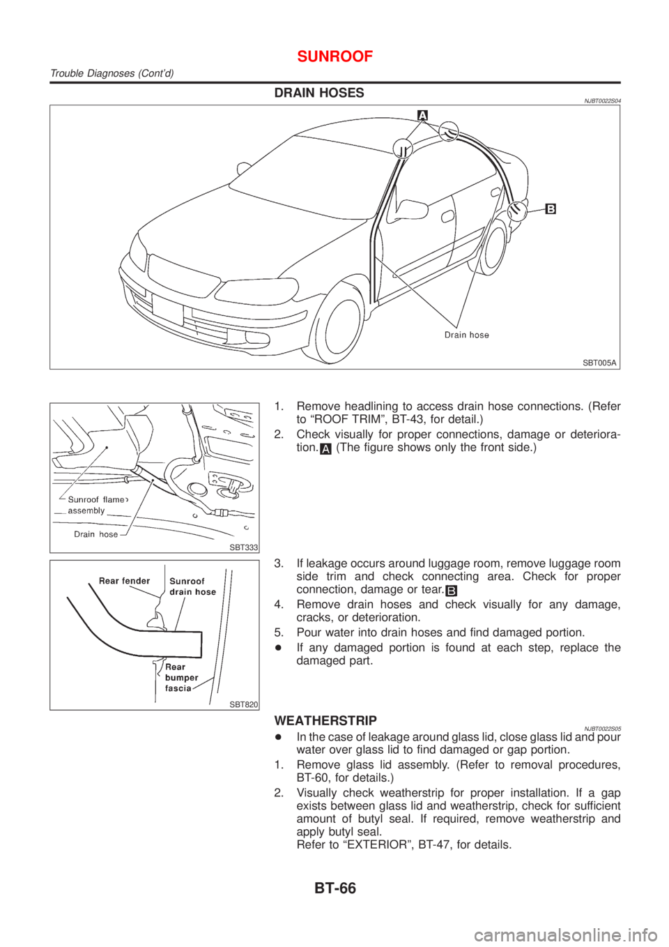
DRAIN HOSESNJBT0022S04
SBT005A
SBT333
1. Remove headlining to access drain hose connections. (Refer
to ªROOF TRIMº, BT-43, for detail.)
2. Check visually for proper connections, damage or deteriora-
tion.
(The figure shows only the front side.)
SBT820
3. If leakage occurs around luggage room, remove luggage room
side trim and check connecting area. Check for proper
connection, damage or tear.
4. Remove drain hoses and check visually for any damage,
cracks, or deterioration.
5. Pour water into drain hoses and find damaged portion.
+If any damaged portion is found at each step, replace the
damaged part.
WEATHERSTRIPNJBT0022S05+In the case of leakage around glass lid, close glass lid and pour
water over glass lid to find damaged or gap portion.
1. Remove glass lid assembly. (Refer to removal procedures,
BT-60, for details.)
2. Visually check weatherstrip for proper installation. If a gap
exists between glass lid and weatherstrip, check for sufficient
amount of butyl seal. If required, remove weatherstrip and
apply butyl seal.
Refer to ªEXTERIORº, BT-47, for details.
SUNROOF
Trouble Diagnoses (Cont'd)
BT-66
Page 1976 of 2493
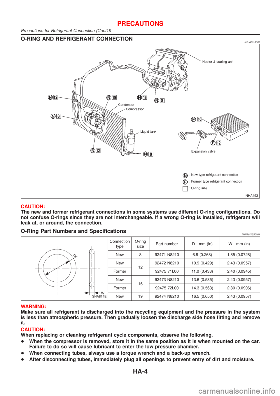
O-RING AND REFRIGERANT CONNECTIONNJHA0115S02
NHA493
CAUTION:
The new and former refrigerant connections in some systems use different O-ring configurations. Do
not confuse O-rings since they are not interchangeable. If a wrong O-ring is installed, refrigerant will
leak at, or around, the connection.
O-Ring Part Numbers and SpecificationsNJHA0115S0201
SHA814E
Connection
typeO-ring
sizePart number D mm (in) W mm (in)
New 8 92471 N8210 6.8 (0.268) 1.85 (0.0728)
New
1292472 N8210 10.9 (0.429) 2.43 (0.0957)
Former 92475 71L00 11.0 (0.433) 2.40 (0.0945)
New
1692473 N8210 13.6 (0.535) 2.43 (0.0957)
Former 92475 72L00 14.3 (0.563) 2.30 (0.0906)
New 19 92474 N8210 16.5 (0.650) 2.43 (0.0957)
WARNING:
Make sure all refrigerant is discharged into the recycling equipment and the pressure in the system
is less than atmospheric pressure. Then gradually loosen the discharge side hose fitting and remove
it.
CAUTION:
When replacing or cleaning refrigerant cycle components, observe the following.
+When the compressor is removed, store it in the same position as it is when mounted on the car.
Failure to do so will cause lubricant to enter the low pressure chamber.
+When connecting tubes, always use a torque wrench and a back-up wrench.
+After disconnecting tubes, immediately plug all openings to prevent entry of dirt and moisture.
PRECAUTIONS
Precautions for Refrigerant Connection (Cont'd)
HA-4
Page 1977 of 2493
+When installing an air conditioner in the vehicle, connect the pipes as the final stage of the opera-
tion. Do not remove the seal caps of pipes and other components until just before required for
connection.
+Allow components stored in cool areas to warm to working area temperature before removing seal
caps. This prevents condensation from forming inside A/C components.
+Thoroughly remove moisture from the refrigeration system before charging the refrigerant.
+Always replace used O-rings.
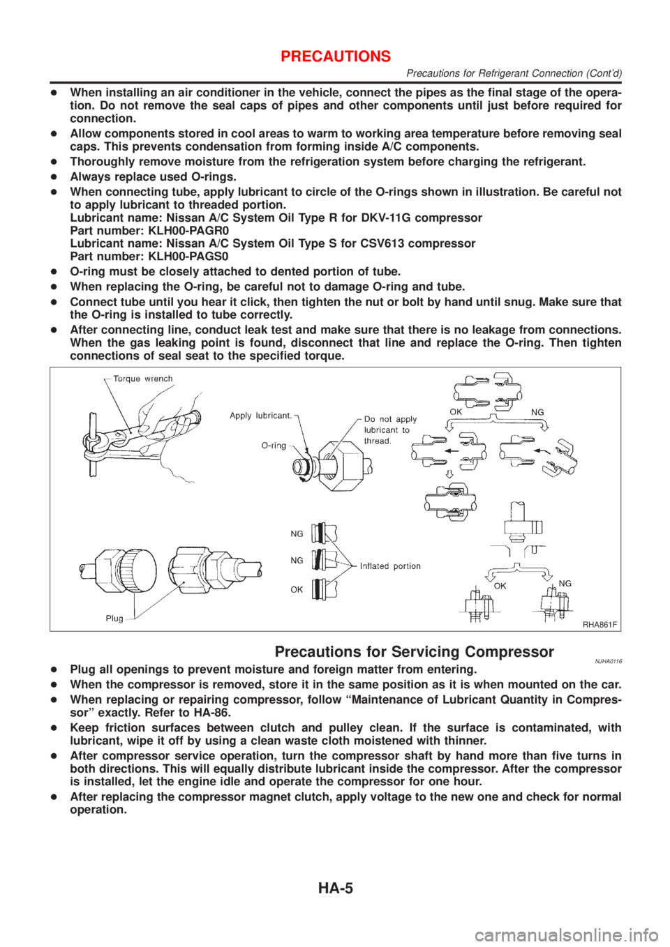
+When connecting tube, apply lubricant to circle of the O-rings shown in illustration. Be careful not
to apply lubricant to threaded portion.
Lubricant name: Nissan A/C System Oil Type R for DKV-11G compressor
Part number: KLH00-PAGR0
Lubricant name: Nissan A/C System Oil Type S for CSV613 compressor
Part number: KLH00-PAGS0
+O-ring must be closely attached to dented portion of tube.
+When replacing the O-ring, be careful not to damage O-ring and tube.
+Connect tube until you hear it click, then tighten the nut or bolt by hand until snug. Make sure that
the O-ring is installed to tube correctly.
+After connecting line, conduct leak test and make sure that there is no leakage from connections.
When the gas leaking point is found, disconnect that line and replace the O-ring. Then tighten
connections of seal seat to the specified torque.
RHA861F
Precautions for Servicing CompressorNJHA0116+Plug all openings to prevent moisture and foreign matter from entering.
+When the compressor is removed, store it in the same position as it is when mounted on the car.
+When replacing or repairing compressor, follow ªMaintenance of Lubricant Quantity in Compres-
sorº exactly. Refer to HA-86.
+Keep friction surfaces between clutch and pulley clean. If the surface is contaminated, with
lubricant, wipe it off by using a clean waste cloth moistened with thinner.
+After compressor service operation, turn the compressor shaft by hand more than five turns in
both directions. This will equally distribute lubricant inside the compressor. After the compressor
is installed, let the engine idle and operate the compressor for one hour.
+After replacing the compressor magnet clutch, apply voltage to the new one and check for normal
operation.
PRECAUTIONS
Precautions for Refrigerant Connection (Cont'd)
HA-5
Page 1989 of 2493

3. Capacity Control=NJHA0207S0203+Refrigerant pressure on suction side is low during high speed driving or when ambient or interior tempera-
ture is low.
+The bellows expands when refrigerant pressure on the suction pressure side drops below approximately
177 kPa (1.77 bar, 1.8 kg/cm
2, 26 psi).
Since suction pressure is low, it makes the suction port close and the discharge port open. Thus, crank-
case pressure becomes high as high pressure enters the crankcase.
+The force acts around the journal pin near the swash plate, and is generated by the pressure difference
before and behind the piston.
The drive lug and journal pin are located where the piston generates the highest pressure. Piston pres-
sure is between suction pressure Ps and discharge pressure Pd, which is near suction pressure Ps. If
crankcase pressure Pc rises due to capacity control, the force around the journal pin makes the swash
plate angle decrease and also the piston stroke decrease. In other words, crankcase pressure increase
triggers pressure difference between the piston and the crankcase. The pressure difference changes the
angle of the swash plate.
RHA474C
DESCRIPTION
CSV613 Variable Displacement Compressor (Cont'd)
HA-17
Page 2072 of 2493

SHA708EA
3. Move probe along component approximately 25 to 50 mm (1
to 2 in)/sec.
Checking ProcedureNJHA0168S03To prevent inaccurate or false readings, make sure there is no
refrigerant vapor, shop chemicals, or cigarette smoke in the
vicinity of the vehicle. Perform the leak test in calm area (low
air/wind movement) so that the leaking refrigerant is not dis-
persed.
1. Turn engine off.
2. Connect a suitable A/C manifold gauge set to the A/C service
ports.
3. Check if the A/C refrigerant pressure is at least 345.2 kPa (3.45
bar, 3.52 kg/cm
2, 50.1 psi) above 16ÉC (61ÉF). If less than
specification, recover/evacuate and recharge the system with
the specified amount of refrigerant.
NOTE:
At temperatures below 16ÉC (61ÉF), leaks may not be detected
since the system may not reach 345.2 kPa (3.45 bar, 3.52 kg/cm
2,
50.1 psi).
4. Conduct the leak test from the high side (compressor dis-
chargeato evaporator inletg) to the low side (evaporator drain
hosehto shaft sealk). Refer to HA-97. Perform a leak check
for the following areas carefully. Clean the component to be
checked and move the leak detector probe completely around
the connection/component.
+Compressor
Check the fitting of high and low pressure hoses, relief valve
and shaft seal.
+Liquid tank
Check the pressure switch, refrigerant pressure sensor, tube
fitting, weld seams and the fusible plug mount.
+Service valves
Check all around the service valves. Ensure service valve caps
are secured on the service valves (to prevent leaks).
NOTE:
After removing A/C manifold gauge set from service valves, wipe
any residue from valves to prevent any false readings by leak
detector.
+Cooling unit (Evaporator)
With engine OFF, turn blower fan on ªHighº for at least 15
seconds to dissipate any refrigerant trace in the cooling unit.
Wait a minimum of 10 minutes accumulation time (refer to the
manufacturer's recommended procedure for actual wait time)
before inserting the leak detector probe into the drain hose.
Keep the probe inserted for at least ten seconds. Use caution
not to contaminate the ptobe tip with water or dirt that may be
in the drain hose.
SERVICE PROCEDURE
Refrigerant Lines (Cont'd)
HA-100
Page 2080 of 2493

MEL043F
+Remove the cell plug using a suitable tool.
+Add distilled water up to the MAX level.
SEL709E
SulphationNJSC0003S0201A battery will be completely discharged if it is left unattended
for a long time and the specific gravity will become less than
1.100. This may result in sulphation on the cell plates.
To determine if a battery has been ªsulphatedº, note its volt-
age and current when charging it. As shown in the figure, less
current and higher voltage are observed in the initial stage of
charging sulphated batteries.
A sulphated battery may sometimes be brought back into ser-
vice by means of a long, slow charge, 12 hours or more, fol-
lowed by a battery capacity test.
MEL042FA
SPECIFIC GRAVITY CHECKNJSC0003S031. Read hydrometer and thermometer indications at eye level.
2. Convert into specific gravity at 20ÉC (68ÉF).
Example:
+When electrolyte temperature is 35ÉC (95ÉF) and specific grav-
ity of electrolyte is 1.230, converted specific gravity at 20ÉC
(68ÉF) is 1.240.
+When electrolyte temperature is 0ÉC (32ÉF) and specific grav-
ity of electrolyte is 1.210, converted specific gravity at 20ÉC
(68ÉF) is 1.196.
BATTERY
How to Handle Battery (Cont'd)
SC-4
Page 2484 of 2493
Engine control module (ECM) ....... EC-327, 554,
604, 664, 666, 670, 672
Engine control system diagram and
chart .............................................. EC-26, 503
Engine coolant temperature sensor
(ECTS) ........................................ EC-163, 572
Engine fail-safe system ........................... EC-123
Engine oil precautions .................................. GI-7
Engine outer component parts ................. EM-11
Engine removal ................................ EM-49, 136
Engine room - See Engine
compartment .......................................... BT-75
Engine serial number ................................. GI-41
Evaporative emission (EVAP)
system ................................................... EC-33
Exhaust gas recirculation (EGR)
valve .................................... EC-285, 353, 400
Exhaust system ................................... FE-11, 27
Exterior ...................................................... BT-47
F
F/PUMP - Wiring diagram ....................... EC-466
FR02 - Wiring diagram ... EC-179, 198, 205, 374
FR02/H - Wiring diagram ................ EC-211, 380
FUEL - Wiring diagram ................... EC-250, 257
Fan switch ................................................. HA-60
Final drive (FF A/T) .................................. AT-424
Final drive (FF M/T) .............. MT-43, 77, 93, 107
Finisher, interior - See Trim ....................... BT-31
Finisher, trunk lid ....................................... BT-45
Floor trim ................................................... BT-31
Fluid temperature sensor (A/T) ................ AT-192
Fluids ........................................................ MA-20
Flywheel (clutch) ....................................... CL-22
Flywheel runout ................................ EM-60, 153
Fog lamp, front, removal and
installation ................................................ BT-7
Fog lamp, front .......................................... EL-60
Fork rod (M/T) .............................. MT-32, 56, 94
Forward clutch ......................................... AT-399
Freeze frame data .............................. EC-59, 70
Front axle .................................................... AX-2
Front bumper ............................................... BT-7
Front combination lamp removal and
installation ................................................ BT-7
Front disc brake ........................................ BR-27
Front door .................................................. BT-16
Front fog lamp removal and
installation ................................................ BT-7
Front fog lamp ........................................... EL-60
Front heated oxygen sensor (HO2S)
heater .......................................... EC-209, 379
Front heated oxygen sensor (HO2S) ..... EC-176,
183, 189, 195, 203, 373
Front seat belt ............................................. RS-5
Front seat .................................................. BT-56
Front suspension ........................................ SU-2
Front washer ............................................ EL-123Front wiper ............................................... EL-123
Fuel cut control (at no load & high
engine speed) ............................... EC-33, 507
Fuel gauge ................................................. EL-89
Fuel injection system .............. EC-248, 255, 505
Fuel injector ............................................ EC-446
Fuel precautions ........................................... GI-8
Fuel pressure check ................................. EC-38
Fuel pressure regulator ............................. EC-39
Fuel pressure release ............................... EC-38
Fuel pump relay ...................................... EC-464
Fuel pump ............................................... EC-464
Fuel system ........................................... FE-5, 16
Fuel tank vacuum relief valve ................... EC-34
Fuse block ............................................... EL-369
Fuse ........................................................... EL-22
Fusible link ................................................. EL-22
G
GLOW - Wiring diagram ......................... EC-677
Garage jack and safety stand .................... GI-45
Gauges ...................................................... EL-89
Gear components (M/T) ............... MT-31, 55, 93
Generator - See Alternator ....................... SC-27
Generic scan tool (GST) ........................... EC-92
Glass .......................................................... BT-17
Glow plug ................................................ EC-677
Glow relay ............................................... EC-677
Grease ...................................................... MA-20
Ground distribution .................................... EL-23
H
H/LAMP - Wiring diagram .......................... EL-40
HEATER - Wiring diagram ........................ HA-24
HFC134a (R134a) system
recaution .................................................. HA-2
HFC134a (R134a) system service
procedure .............................................. HA-84
HFC134a (R134a) system service
tools ....................................................... HA-11
HFC134a system service equipment
precaution ................................................ HA-6
HORN - Wiring diagram .......................... EL-135
HSEAT - Wiring diagram ......................... EL-163
Harness connector ...................................... EL-5
Harness layout ......................................... EL-324
Hazard warning lamp ................................ EL-65
Headlamp removal and installation ............. BT-7
Headlamp washer .................................... EL-133
Headlamp .................................................. EL-40
Headlining - See Roof trim ........................ BT-43
Heated oxygen sensor (HO2S)
(front) .......... EC-176, 183, 189, 195, 203, 373
Heated oxygen sensor (HO2S) heater
(front) ........................................... EC-209, 379
ALPHABETICAL INDEX
IDX-4