torque NISSAN ALMERA N16 2001 Electronic Repair Manual
[x] Cancel search | Manufacturer: NISSAN, Model Year: 2001, Model line: ALMERA N16, Model: NISSAN ALMERA N16 2001Pages: 2493, PDF Size: 66.97 MB
Page 1485 of 2493
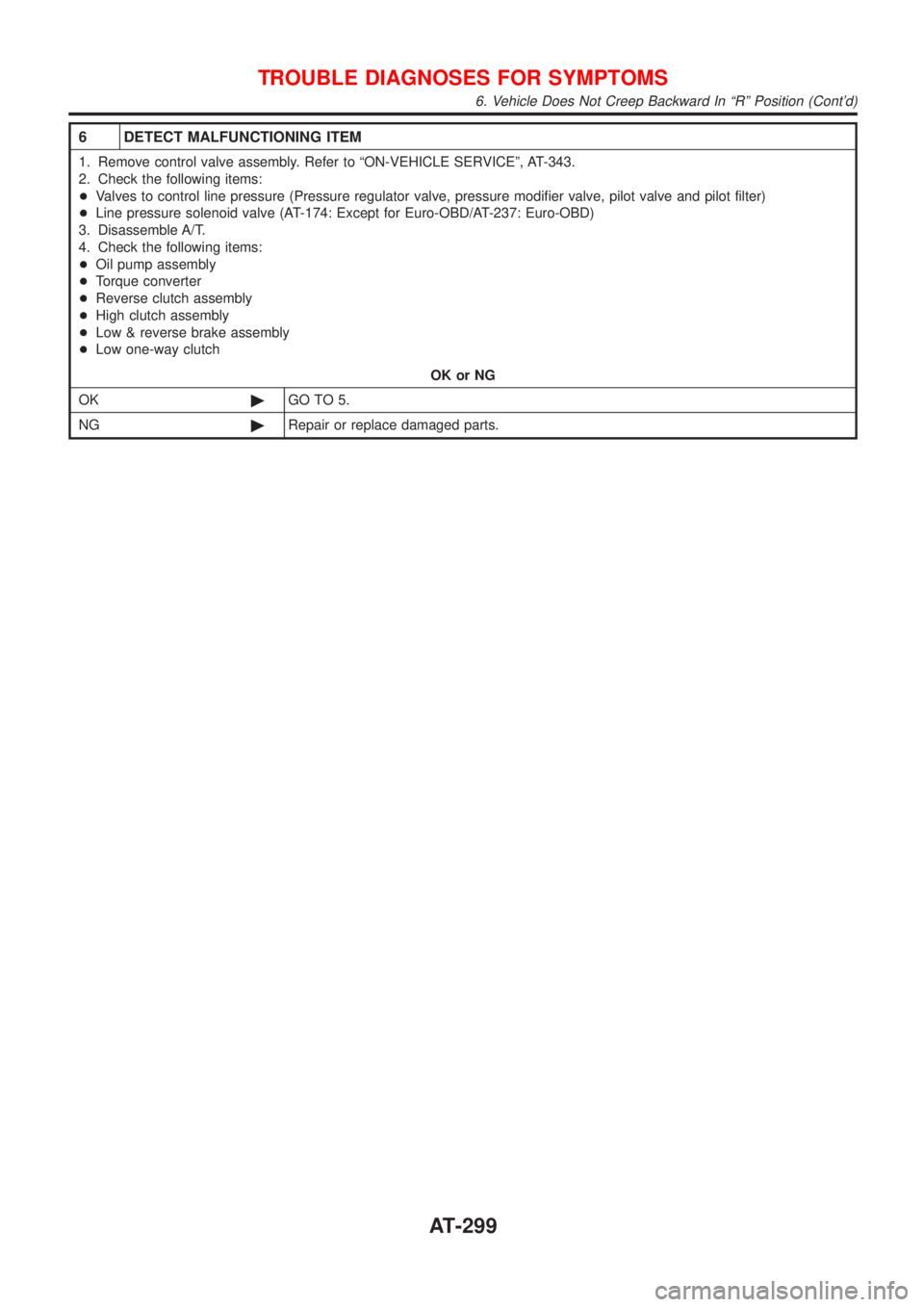
6 DETECT MALFUNCTIONING ITEM
1. Remove control valve assembly. Refer to ªON-VEHICLE SERVICEº, AT-343.
2. Check the following items:
+Valves to control line pressure (Pressure regulator valve, pressure modifier valve, pilot valve and pilot filter)
+Line pressure solenoid valve (AT-174: Except for Euro-OBD/AT-237: Euro-OBD)
3. Disassemble A/T.
4. Check the following items:
+Oil pump assembly
+Torque converter
+Reverse clutch assembly
+High clutch assembly
+Low & reverse brake assembly
+Low one-way clutch
OK or NG
OK©GO TO 5.
NG©Repair or replace damaged parts.
TROUBLE DIAGNOSES FOR SYMPTOMS
6. Vehicle Does Not Creep Backward In ªRº Position (Cont'd)
AT-299
Page 1488 of 2493
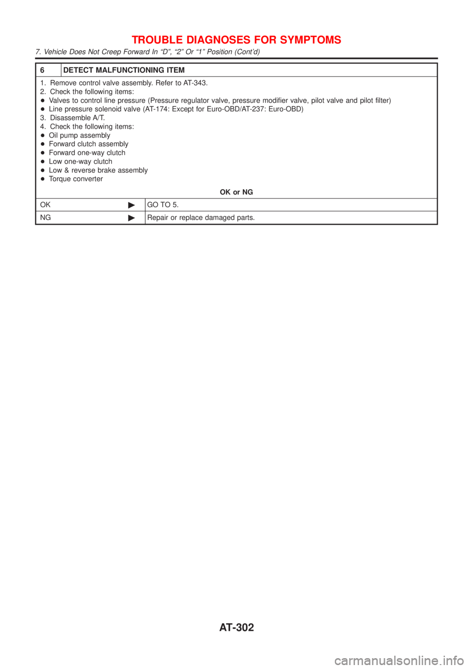
6 DETECT MALFUNCTIONING ITEM
1. Remove control valve assembly. Refer to AT-343.
2. Check the following items:
+Valves to control line pressure (Pressure regulator valve, pressure modifier valve, pilot valve and pilot filter)
+Line pressure solenoid valve (AT-174: Except for Euro-OBD/AT-237: Euro-OBD)
3. Disassemble A/T.
4. Check the following items:
+Oil pump assembly
+Forward clutch assembly
+Forward one-way clutch
+Low one-way clutch
+Low & reverse brake assembly
+Torque converter
OK or NG
OK©GO TO 5.
NG©Repair or replace damaged parts.
TROUBLE DIAGNOSES FOR SYMPTOMS
7. Vehicle Does Not Creep Forward In ªDº, ª2º Or ª1º Position (Cont'd)
AT-302
Page 1491 of 2493
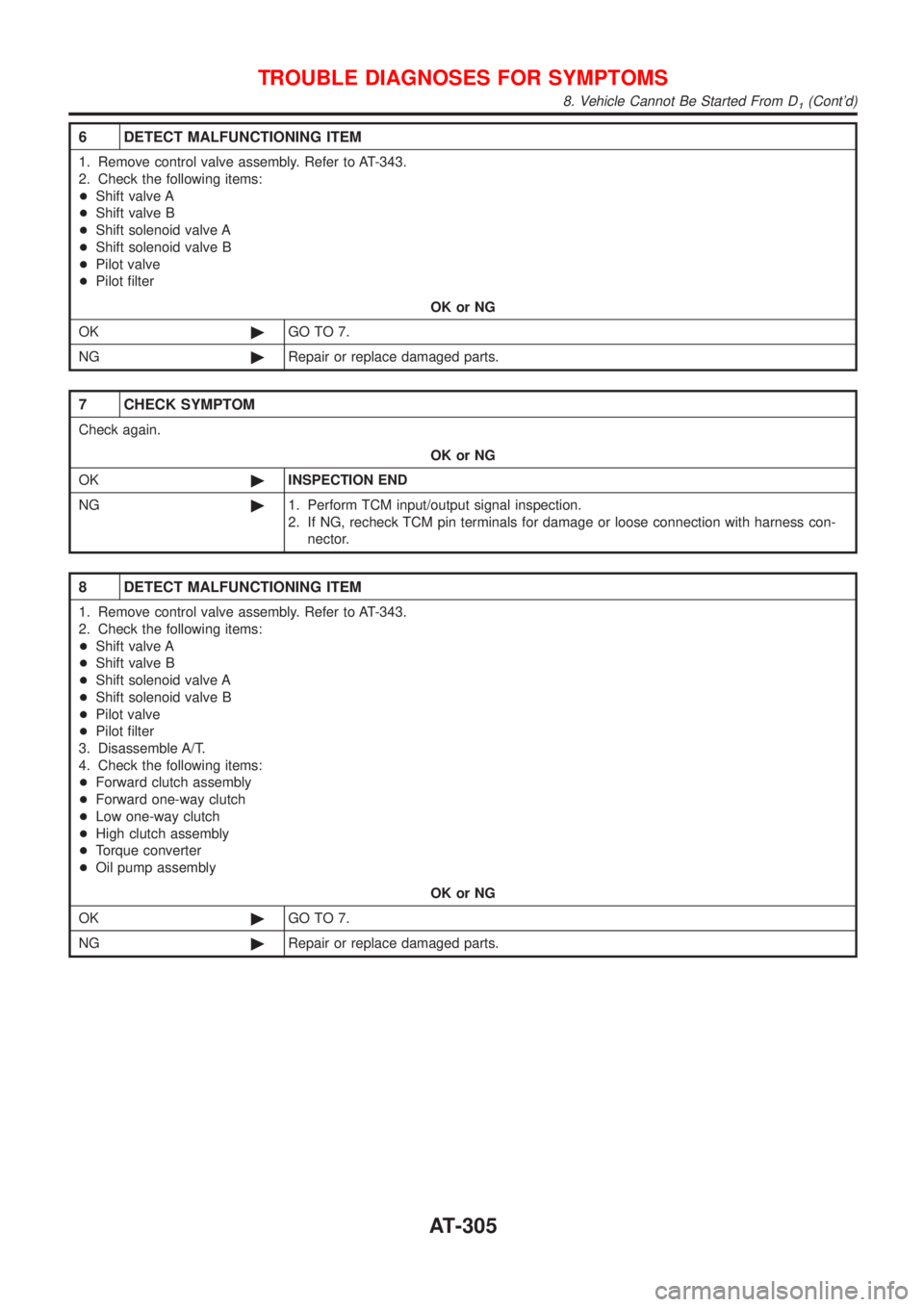
6 DETECT MALFUNCTIONING ITEM
1. Remove control valve assembly. Refer to AT-343.
2. Check the following items:
+Shift valve A
+Shift valve B
+Shift solenoid valve A
+Shift solenoid valve B
+Pilot valve
+Pilot filter
OK or NG
OK©GO TO 7.
NG©Repair or replace damaged parts.
7 CHECK SYMPTOM
Check again.
OK or NG
OK©INSPECTION END
NG©1. Perform TCM input/output signal inspection.
2. If NG, recheck TCM pin terminals for damage or loose connection with harness con-
nector.
8 DETECT MALFUNCTIONING ITEM
1. Remove control valve assembly. Refer to AT-343.
2. Check the following items:
+Shift valve A
+Shift valve B
+Shift solenoid valve A
+Shift solenoid valve B
+Pilot valve
+Pilot filter
3. Disassemble A/T.
4. Check the following items:
+Forward clutch assembly
+Forward one-way clutch
+Low one-way clutch
+High clutch assembly
+Torque converter
+Oil pump assembly
OK or NG
OK©GO TO 7.
NG©Repair or replace damaged parts.
TROUBLE DIAGNOSES FOR SYMPTOMS
8. Vehicle Cannot Be Started From D1(Cont'd)
AT-305
Page 1500 of 2493

6 CHECK SYMPTOM
Check again.
OK or NG
OK©INSPECTION END
NG©1. Perform TCM input/output signal inspection.
2. If NG, recheck TCM pin terminals for damage or loose connection with harness con-
nector.
7 DETECT MALFUNCTIONING ITEM
1. Remove control valve assembly. Refer to AT-343.
2. Check the following items:
+Shift valve B
+Overrun clutch control valve
+Shift solenoid valve B
+Pilot valve
+Pilot filter
3. Disassemble A/T.
4. Check the following items:
+Servo piston assembly
+Brake band
+Torque converter
+Oil pump assembly
OK or NG
OK©GO TO 6.
NG©Repair or replace damaged parts.
TROUBLE DIAGNOSES FOR SYMPTOMS
11. A/T Does Not Shift: D3®D4(Cont'd)
AT-314
Page 1501 of 2493

12. A/T Does Not Perform Lock-up=NJAT0342SYMPTOM:
A/T does not perform lock-up at the specified speed.
1 CHECK SELF-DIAGNOSTIC RESULTS
Does self-diagnosis show damage to torque converter clutch solenoid valve circuit after cruise test?
SAT346H
YesorNo
Ye s©Check torque converter clutch solenoid valve circuit. Refer to AT-157 (Except for Euro-
OBD)/AT-231 (Euro-OBD).
No©GO TO 2.
2 CHECK THROTTLE POSITION SENSOR
Check throttle position sensor. Refer to EC-168, ªDTC P0120 THROTTLE POSITION SENSORº.
SAT004K
OK or NG
OK©GO TO 3.
NG©Repair or replace throttle position sensor.
3 DETECT MALFUNCTIONING ITEM
1. Remove control valve. Refer to AT-343.
2. Check following items:
+Torque converter clutch control valve
+Torque converter relief valve
+Torque converter clutch solenoid valve
+Pilot valve
+Pilot filter
OK or NG
OK©GO TO 4.
NG©Repair or replace damaged parts.
TROUBLE DIAGNOSES FOR SYMPTOMS
12. A/T Does Not Perform Lock-up
AT-315
Page 1503 of 2493
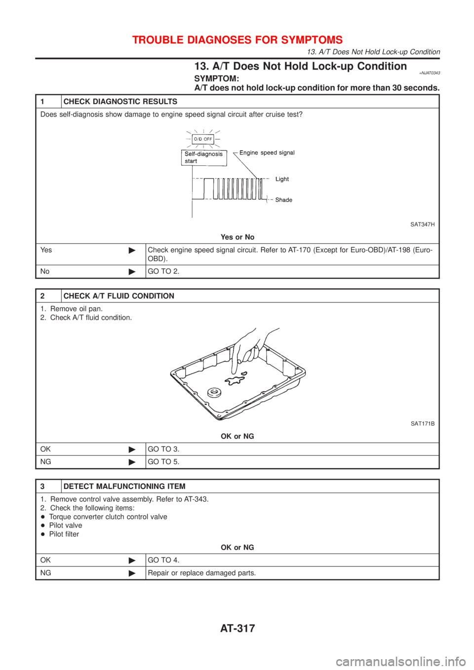
13. A/T Does Not Hold Lock-up Condition=NJAT0343SYMPTOM:
A/T does not hold lock-up condition for more than 30 seconds.
1 CHECK DIAGNOSTIC RESULTS
Does self-diagnosis show damage to engine speed signal circuit after cruise test?
SAT347H
YesorNo
Ye s©Check engine speed signal circuit. Refer to AT-170 (Except for Euro-OBD)/AT-198 (Euro-
OBD).
No©GO TO 2.
2 CHECK A/T FLUID CONDITION
1. Remove oil pan.
2. Check A/T fluid condition.
SAT171B
OK or NG
OK©GO TO 3.
NG©GO TO 5.
3 DETECT MALFUNCTIONING ITEM
1. Remove control valve assembly. Refer to AT-343.
2. Check the following items:
+Torque converter clutch control valve
+Pilot valve
+Pilot filter
OK or NG
OK©GO TO 4.
NG©Repair or replace damaged parts.
TROUBLE DIAGNOSES FOR SYMPTOMS
13. A/T Does Not Hold Lock-up Condition
AT-317
Page 1504 of 2493
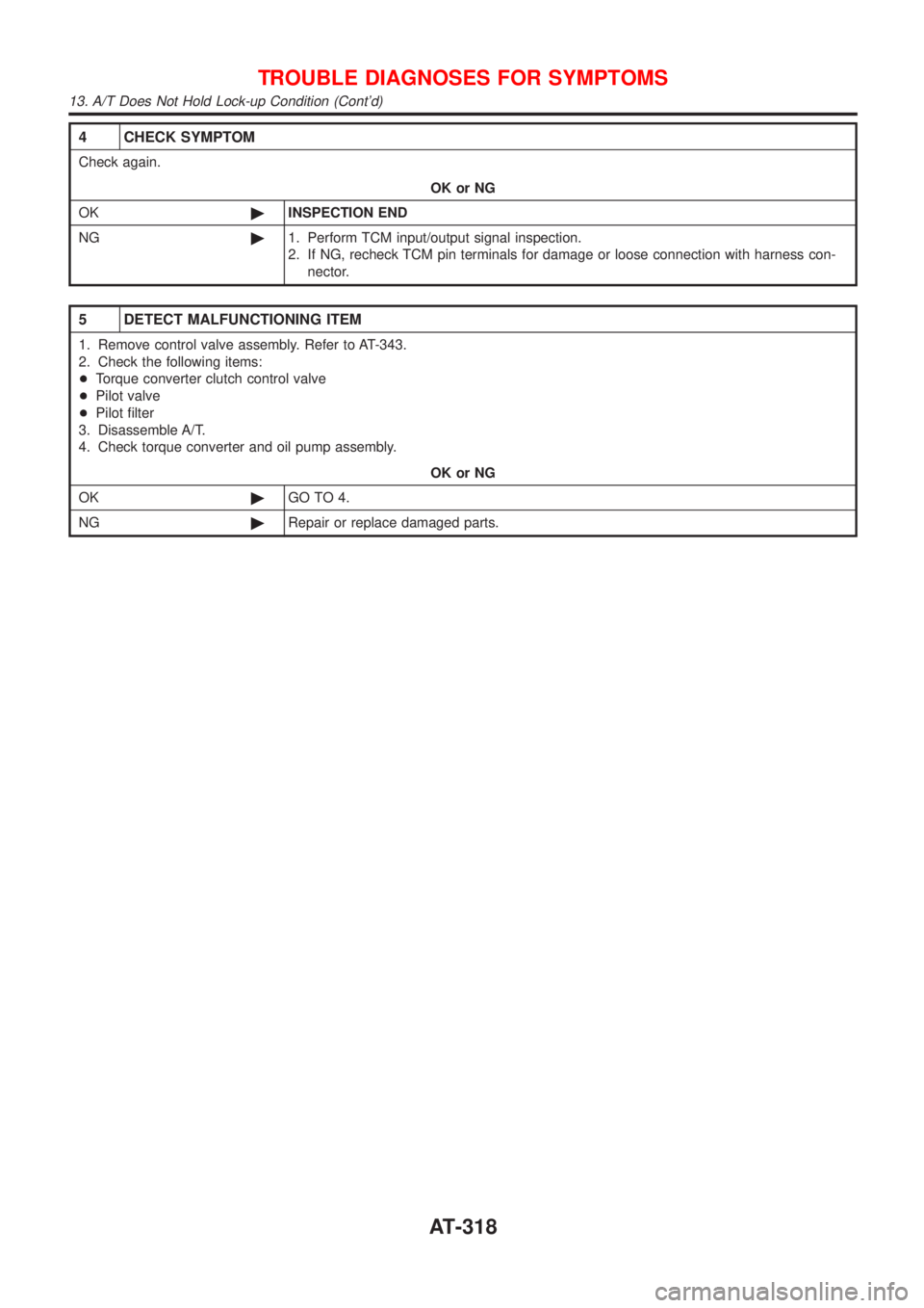
4 CHECK SYMPTOM
Check again.
OK or NG
OK©INSPECTION END
NG©1. Perform TCM input/output signal inspection.
2. If NG, recheck TCM pin terminals for damage or loose connection with harness con-
nector.
5 DETECT MALFUNCTIONING ITEM
1. Remove control valve assembly. Refer to AT-343.
2. Check the following items:
+Torque converter clutch control valve
+Pilot valve
+Pilot filter
3. Disassemble A/T.
4. Check torque converter and oil pump assembly.
OK or NG
OK©GO TO 4.
NG©Repair or replace damaged parts.
TROUBLE DIAGNOSES FOR SYMPTOMS
13. A/T Does Not Hold Lock-up Condition (Cont'd)
AT-318
Page 1532 of 2493
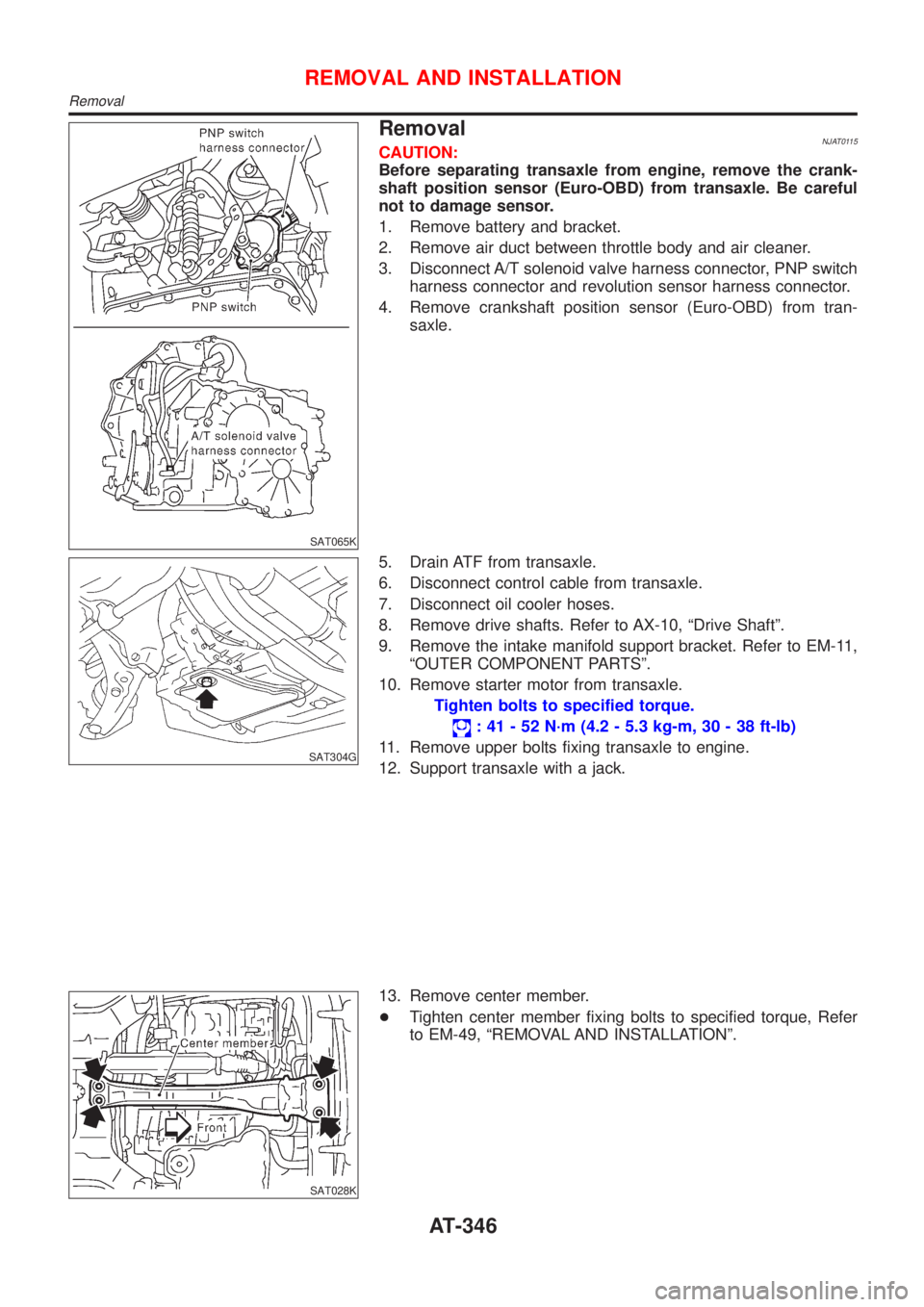
SAT065K
RemovalNJAT0115CAUTION:
Before separating transaxle from engine, remove the crank-
shaft position sensor (Euro-OBD) from transaxle. Be careful
not to damage sensor.
1. Remove battery and bracket.
2. Remove air duct between throttle body and air cleaner.
3. Disconnect A/T solenoid valve harness connector, PNP switch
harness connector and revolution sensor harness connector.
4. Remove crankshaft position sensor (Euro-OBD) from tran-
saxle.
SAT304G
5. Drain ATF from transaxle.
6. Disconnect control cable from transaxle.
7. Disconnect oil cooler hoses.
8. Remove drive shafts. Refer to AX-10, ªDrive Shaftº.
9. Remove the intake manifold support bracket. Refer to EM-11,
ªOUTER COMPONENT PARTSº.
10. Remove starter motor from transaxle.
Tighten bolts to specified torque.
: 41 - 52 N´m (4.2 - 5.3 kg-m, 30 - 38 ft-lb)
11. Remove upper bolts fixing transaxle to engine.
12. Support transaxle with a jack.
SAT028K
13. Remove center member.
+Tighten center member fixing bolts to specified torque, Refer
to EM-49, ªREMOVAL AND INSTALLATIONº.
REMOVAL AND INSTALLATION
Removal
AT-346
Page 1533 of 2493
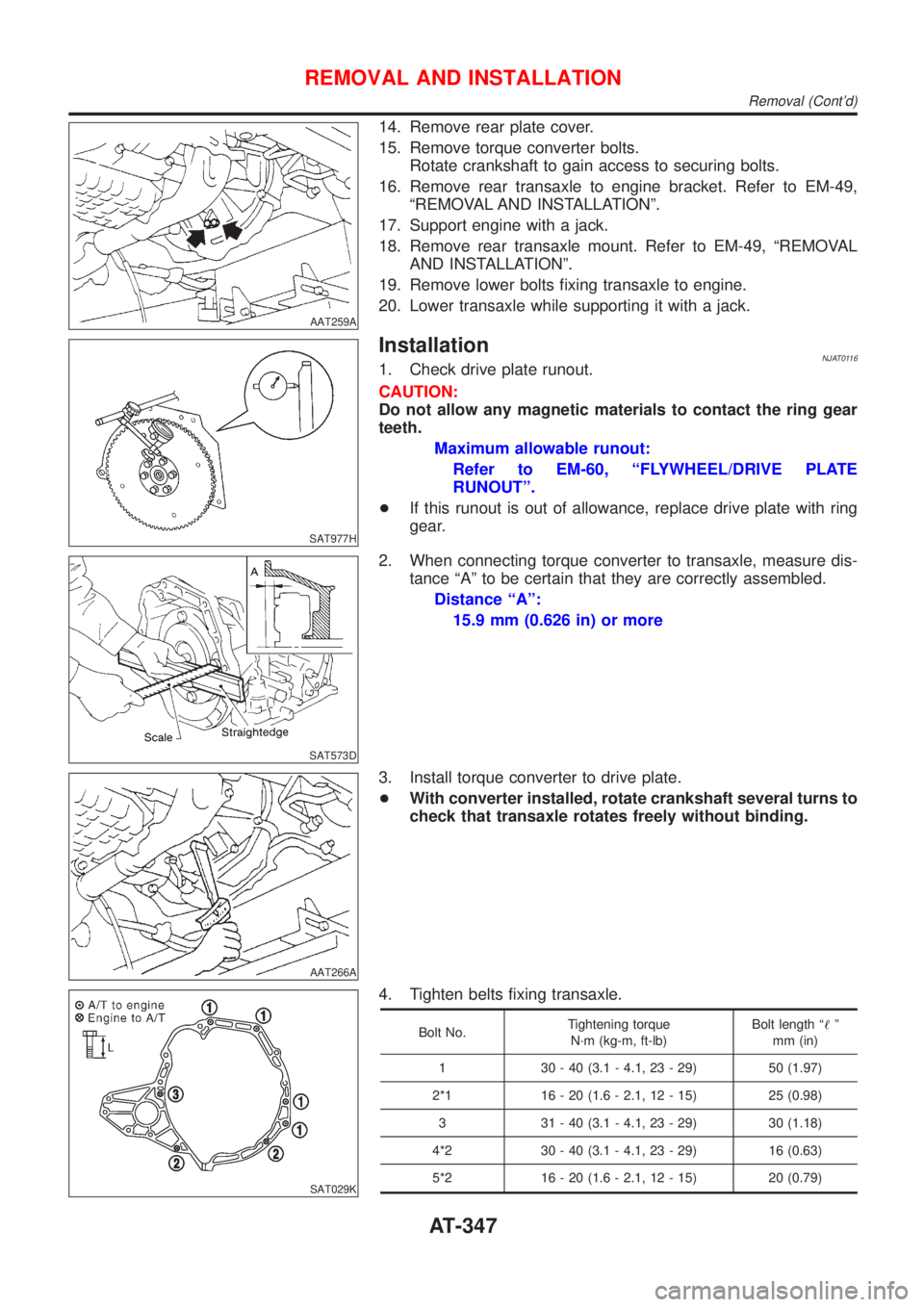
AAT259A
14. Remove rear plate cover.
15. Remove torque converter bolts.
Rotate crankshaft to gain access to securing bolts.
16. Remove rear transaxle to engine bracket. Refer to EM-49,
ªREMOVAL AND INSTALLATIONº.
17. Support engine with a jack.
18. Remove rear transaxle mount. Refer to EM-49, ªREMOVAL
AND INSTALLATIONº.
19. Remove lower bolts fixing transaxle to engine.
20. Lower transaxle while supporting it with a jack.
SAT977H
InstallationNJAT01161. Check drive plate runout.
CAUTION:
Do not allow any magnetic materials to contact the ring gear
teeth.
Maximum allowable runout:
Refer to EM-60, ªFLYWHEEL/DRIVE PLATE
RUNOUTº.
+If this runout is out of allowance, replace drive plate with ring
gear.
SAT573D
2. When connecting torque converter to transaxle, measure dis-
tance ªAº to be certain that they are correctly assembled.
Distance ªAº:
15.9 mm (0.626 in) or more
AAT266A
3. Install torque converter to drive plate.
+With converter installed, rotate crankshaft several turns to
check that transaxle rotates freely without binding.
SAT029K
4. Tighten belts fixing transaxle.
Bolt No.Tightening torque
N´m (kg-m, ft-lb)Bolt length ª!º
mm (in)
1 30 - 40 (3.1 - 4.1, 23 - 29) 50 (1.97)
2*1 16 - 20 (1.6 - 2.1, 12 - 15) 25 (0.98)
3 31 - 40 (3.1 - 4.1, 23 - 29) 30 (1.18)
4*2 30 - 40 (3.1 - 4.1, 23 - 29) 16 (0.63)
5*2 16 - 20 (1.6 - 2.1, 12 - 15) 20 (0.79)
REMOVAL AND INSTALLATION
Removal (Cont'd)
AT-347
Page 1540 of 2493
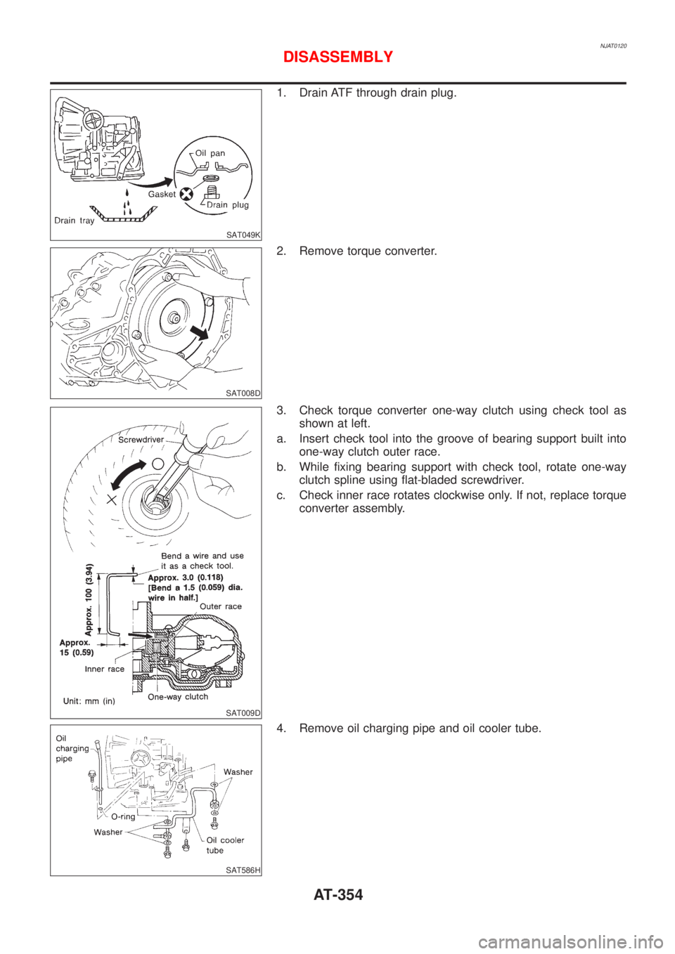
NJAT0120
SAT049K
1. Drain ATF through drain plug.
SAT008D
2. Remove torque converter.
SAT009D
3. Check torque converter one-way clutch using check tool as
shown at left.
a. Insert check tool into the groove of bearing support built into
one-way clutch outer race.
b. While fixing bearing support with check tool, rotate one-way
clutch spline using flat-bladed screwdriver.
c. Check inner race rotates clockwise only. If not, replace torque
converter assembly.
SAT586H
4. Remove oil charging pipe and oil cooler tube.
DISASSEMBLY
AT-354