NISSAN ALMERA N16 2001 Electronic Repair Manual
Manufacturer: NISSAN, Model Year: 2001, Model line: ALMERA N16, Model: NISSAN ALMERA N16 2001Pages: 2493, PDF Size: 66.97 MB
Page 181 of 2493
JEM137G
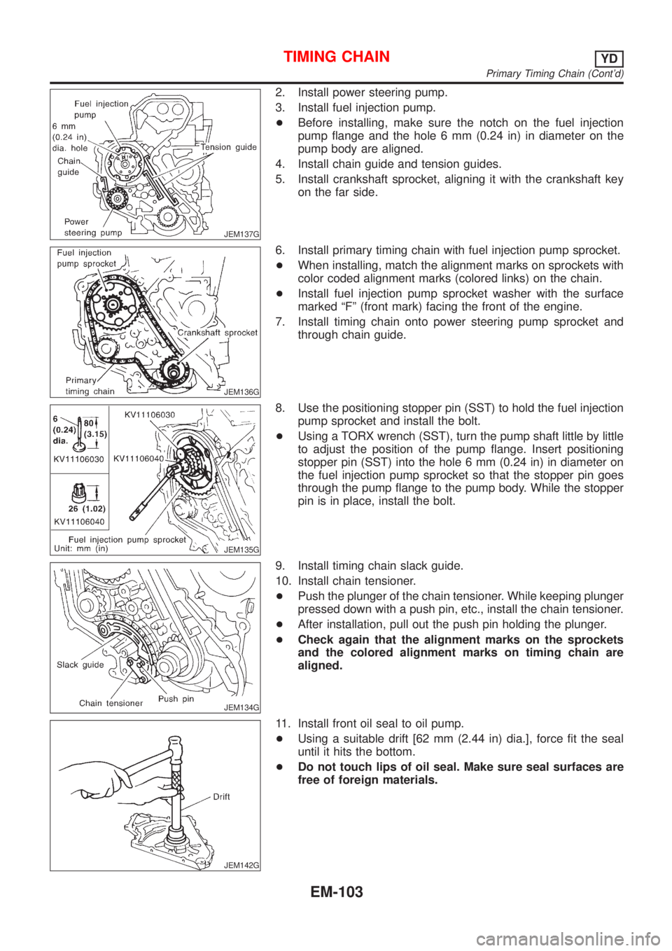
2. Install power steering pump.
3. Install fuel injection pump.
+Before installing, make sure the notch on the fuel injection
pump flange and the hole 6 mm (0.24 in) in diameter on the
pump body are aligned.
4. Install chain guide and tension guides.
5. Install crankshaft sprocket, aligning it with the crankshaft key
on the far side.
JEM136G
6. Install primary timing chain with fuel injection pump sprocket.
+When installing, match the alignment marks on sprockets with
color coded alignment marks (colored links) on the chain.
+Install fuel injection pump sprocket washer with the surface
marked ªFº (front mark) facing the front of the engine.
7. Install timing chain onto power steering pump sprocket and
through chain guide.
JEM135G
8. Use the positioning stopper pin (SST) to hold the fuel injection
pump sprocket and install the bolt.
+Using a TORX wrench (SST), turn the pump shaft little by little
to adjust the position of the pump flange. Insert positioning
stopper pin (SST) into the hole 6 mm (0.24 in) in diameter on
the fuel injection pump sprocket so that the stopper pin goes
through the pump flange to the pump body. While the stopper
pin is in place, install the bolt.
JEM134G
9. Install timing chain slack guide.
10. Install chain tensioner.
+Push the plunger of the chain tensioner. While keeping plunger
pressed down with a push pin, etc., install the chain tensioner.
+After installation, pull out the push pin holding the plunger.
+Check again that the alignment marks on the sprockets
and the colored alignment marks on timing chain are
aligned.
JEM142G
11. Install front oil seal to oil pump.
+Using a suitable drift [62 mm (2.44 in) dia.], force fit the seal
until it hits the bottom.
+Do not touch lips of oil seal. Make sure seal surfaces are
free of foreign materials.
TIMING CHAINYD
Primary Timing Chain (Cont'd)
EM-103
Page 182 of 2493
JEM143G
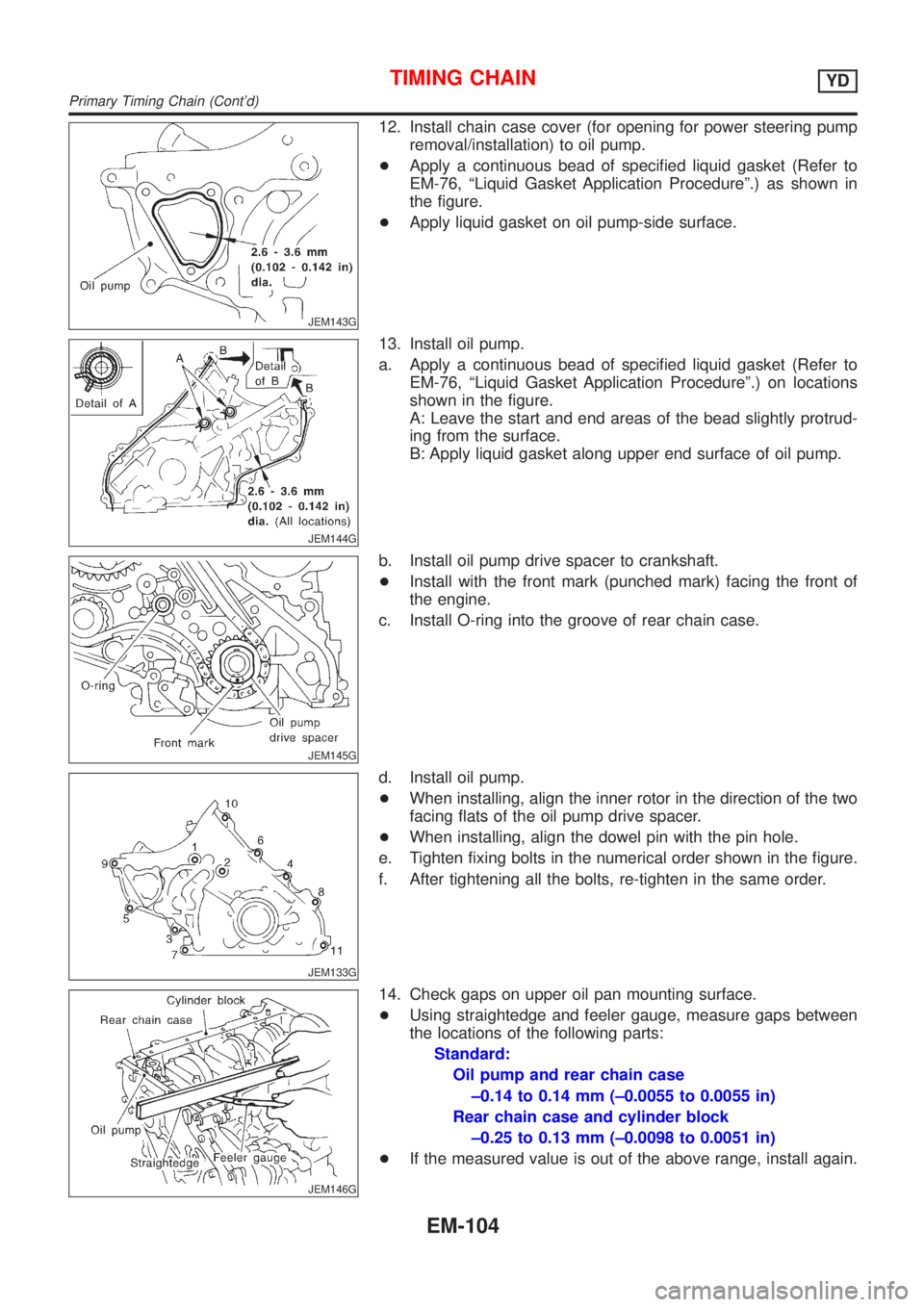
12. Install chain case cover (for opening for power steering pump
removal/installation) to oil pump.
+Apply a continuous bead of specified liquid gasket (Refer to
EM-76, ªLiquid Gasket Application Procedureº.) as shown in
the figure.
+Apply liquid gasket on oil pump-side surface.
JEM144G
13. Install oil pump.
a. Apply a continuous bead of specified liquid gasket (Refer to
EM-76, ªLiquid Gasket Application Procedureº.) on locations
shown in the figure.
A: Leave the start and end areas of the bead slightly protrud-
ing from the surface.
B: Apply liquid gasket along upper end surface of oil pump.
JEM145G
b. Install oil pump drive spacer to crankshaft.
+Install with the front mark (punched mark) facing the front of
the engine.
c. Install O-ring into the groove of rear chain case.
JEM133G
d. Install oil pump.
+When installing, align the inner rotor in the direction of the two
facing flats of the oil pump drive spacer.
+When installing, align the dowel pin with the pin hole.
e. Tighten fixing bolts in the numerical order shown in the figure.
f. After tightening all the bolts, re-tighten in the same order.
JEM146G
14. Check gaps on upper oil pan mounting surface.
+Using straightedge and feeler gauge, measure gaps between
the locations of the following parts:
Standard:
Oil pump and rear chain case
±0.14 to 0.14 mm (±0.0055 to 0.0055 in)
Rear chain case and cylinder block
±0.25 to 0.13 mm (±0.0098 to 0.0051 in)
+If the measured value is out of the above range, install again.
TIMING CHAINYD
Primary Timing Chain (Cont'd)
EM-104
Page 183 of 2493
JEM147G
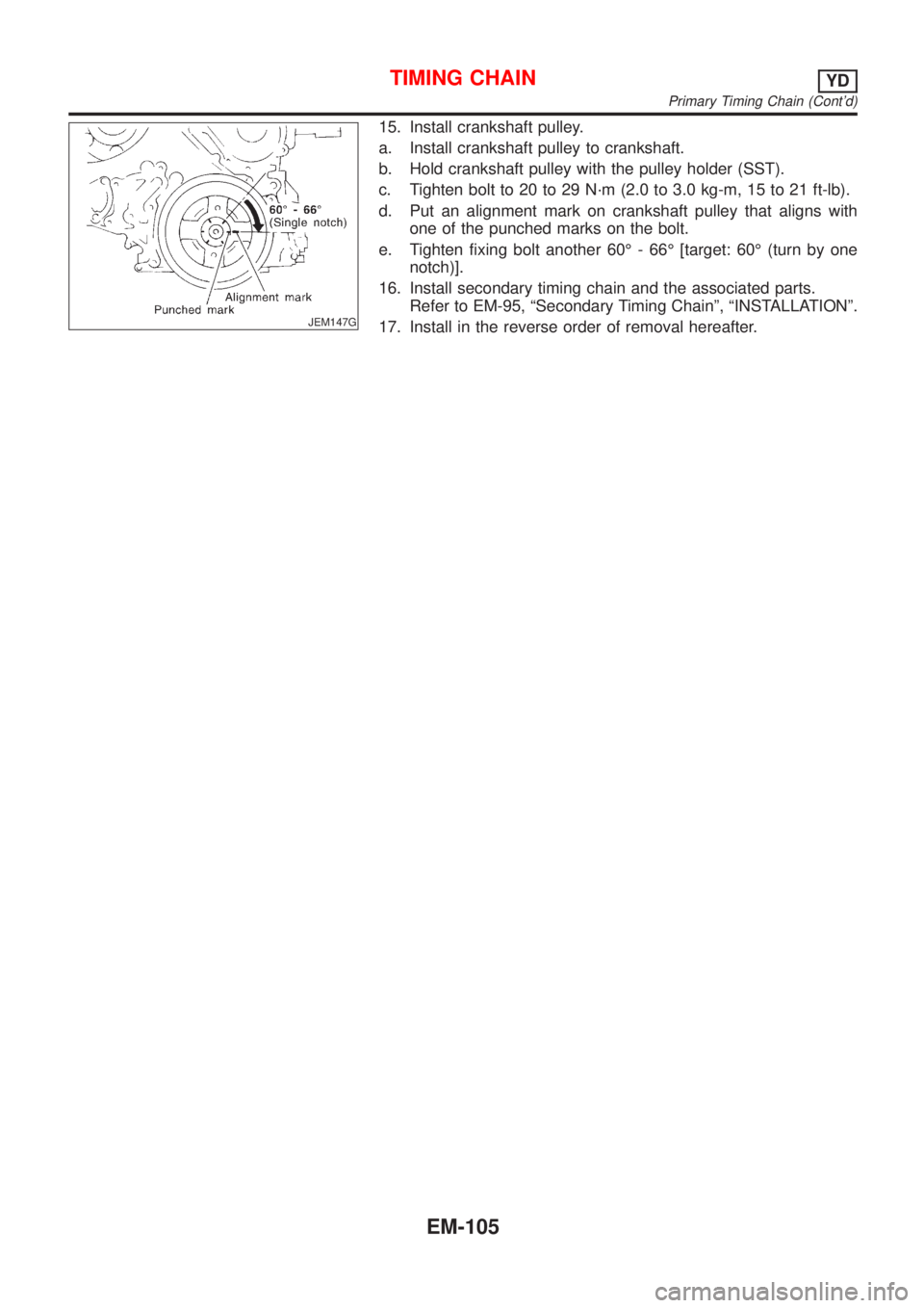
15. Install crankshaft pulley.
a. Install crankshaft pulley to crankshaft.
b. Hold crankshaft pulley with the pulley holder (SST).
c. Tighten bolt to 20 to 29 N´m (2.0 to 3.0 kg-m, 15 to 21 ft-lb).
d. Put an alignment mark on crankshaft pulley that aligns with
one of the punched marks on the bolt.
e. Tighten fixing bolt another 60É - 66É [target: 60É (turn by one
notch)].
16. Install secondary timing chain and the associated parts.
Refer to EM-95, ªSecondary Timing Chainº, ªINSTALLATIONº.
17. Install in the reverse order of removal hereafter.
TIMING CHAINYD
Primary Timing Chain (Cont'd)
EM-105
Page 184 of 2493
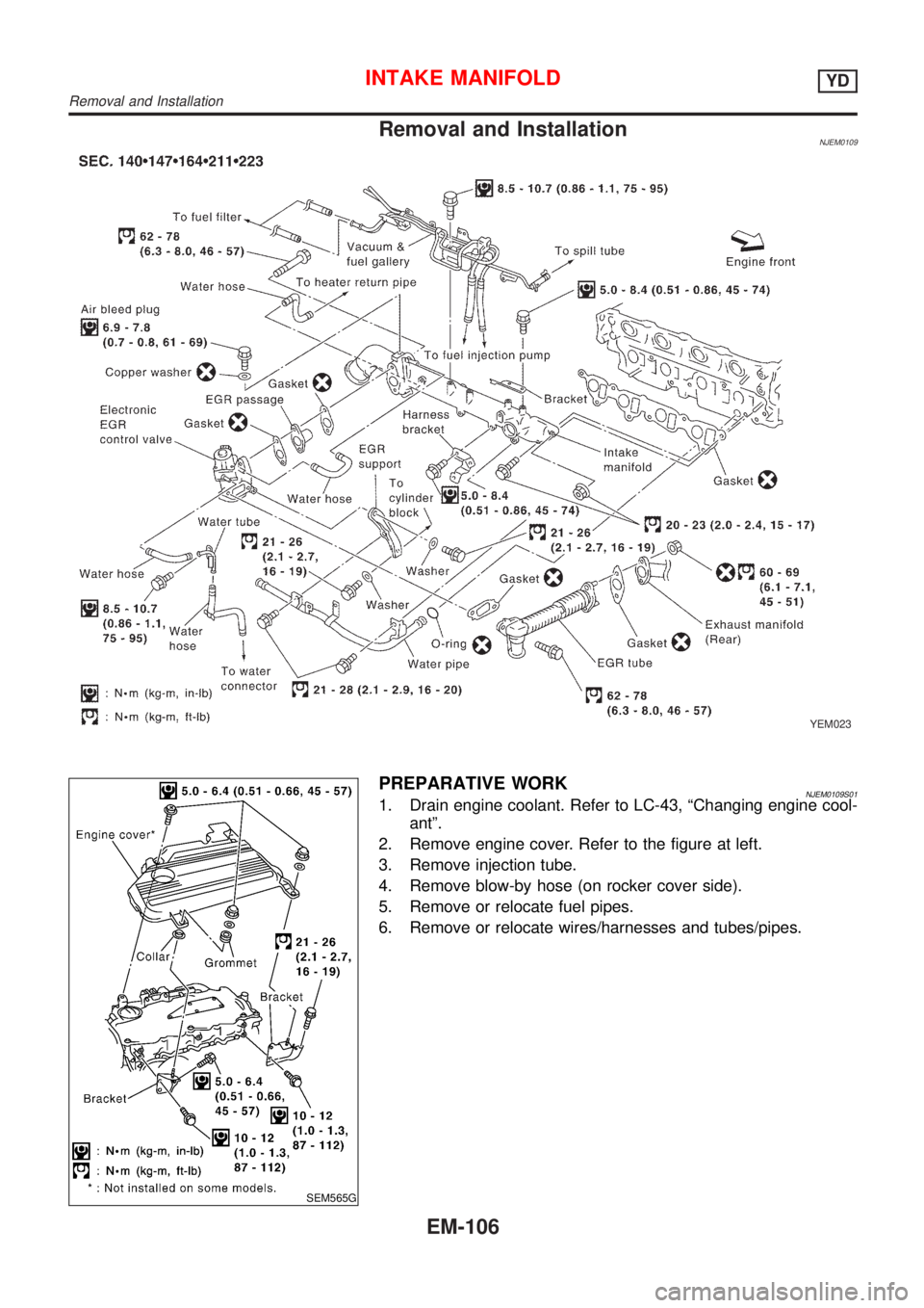
Removal and InstallationNJEM0109
YEM023
SEM565G
PREPARATIVE WORKNJEM0109S011. Drain engine coolant. Refer to LC-43, ªChanging engine cool-
antº.
2. Remove engine cover. Refer to the figure at left.
3. Remove injection tube.
4. Remove blow-by hose (on rocker cover side).
5. Remove or relocate fuel pipes.
6. Remove or relocate wires/harnesses and tubes/pipes.
INTAKE MANIFOLDYD
Removal and Installation
EM-106
Page 185 of 2493
JEM238G
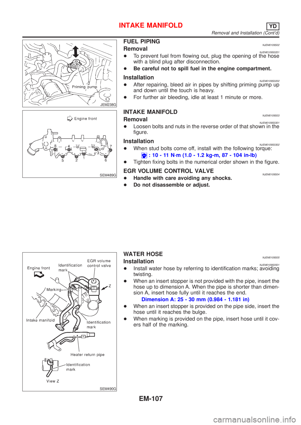
FUEL PIPINGNJEM0109S02RemovalNJEM0109S0201+To prevent fuel from flowing out, plug the opening of the hose
with a blind plug after disconnection.
+Be careful not to spill fuel in the engine compartment.
InstallationNJEM0109S0202+After repairing, bleed air in pipes by shifting priming pump up
and down until the touch is heavy.
+For further air bleeding, idle at least 1 minute or more.
SEM489G
INTAKE MANIFOLDNJEM0109S03RemovalNJEM0109S0301+Loosen bolts and nuts in the reverse order of that shown in the
figure.
InstallationNJEM0109S0302+When stud bolts come off, install with the following torque:
: 10 - 11 N´m (1.0 - 1.2 kg-m, 87 - 104 in-lb)
+Tighten fixing bolts in the numerical order shown in the figure.
EGR VOLUME CONTROL VALVENJEM0109S04+Handle with care avoiding any shocks.
+Do not disassemble or adjust.
SEM490G
WATER HOSENJEM0109S05InstallationNJEM0109S0501+Install water hose by referring to identification marks; avoiding
twisting.
+When an insert stopper is not provided with the pipe, insert the
hose up to dimension A. When the pipe is shorter than dimen-
sion A, insert hose fully until it reaches the end.
Dimension A: 25 - 30 mm (0.984 - 1.181 in)
+When an insert stopper is provided on the pipe side, insert the
hose until it reaches the bulge.
+When marking is provided on the pipe, insert hose until it cov-
ers half of the marking.
INTAKE MANIFOLDYD
Removal and Installation (Cont'd)
EM-107
Page 186 of 2493
SEM491G
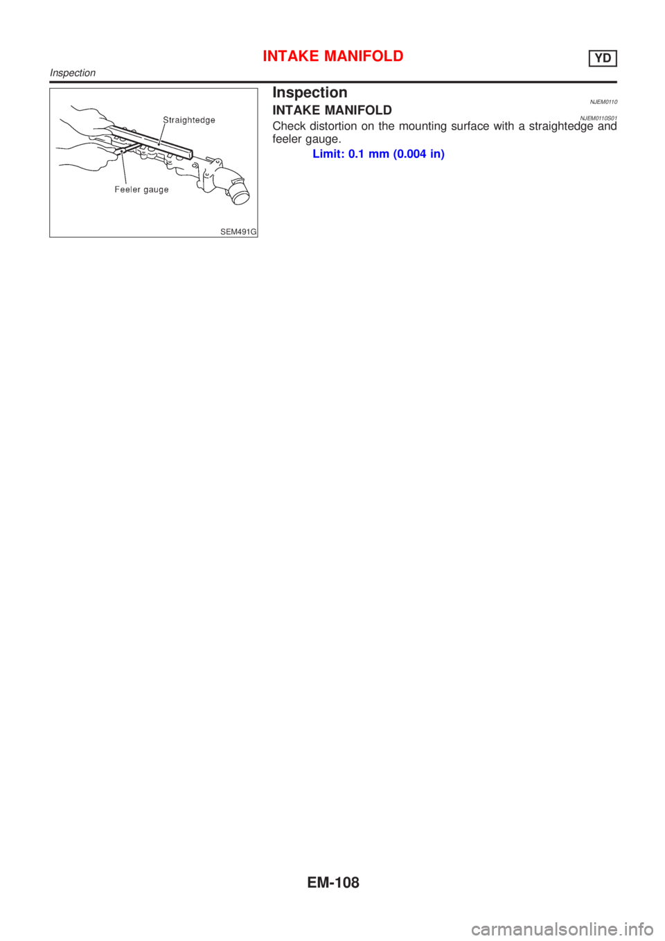
InspectionNJEM0110INTAKE MANIFOLDNJEM0110S01Check distortion on the mounting surface with a straightedge and
feeler gauge.
Limit: 0.1 mm (0.004 in)
INTAKE MANIFOLDYD
Inspection
EM-108
Page 187 of 2493
Removal and InstallationNJEM0101
JEM264G
PREPARATIVE WORKNJEM0101S01Remove the following parts.
+Under cover
+Engine coolant (drain)
Refer to LC-43, ªChanging Engine Coolantº.
+Radiator upper hose
+Cooling fan
Refer to LC-42, ªRadiatorº.
+Radiator mount bracket
+Water inlet pipe
+Exhaust front tube (disconnect)
Refer to FE-27, ªRemoval and Installationº, ªEXHAUST SYS-
TEMº.
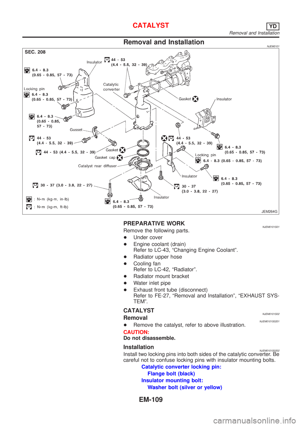
CATALYSTNJEM0101S02RemovalNJEM0101S0201+Remove the catalyst, refer to above illustration.
CAUTION:
Do not disassemble.
InstallationNJEM0101S0202Install two locking pins into both sides of the catalytic converter. Be
careful not to confuse locking pins with insulator mounting bolts.
Catalytic converter locking pin:
Flange bolt (black)
Insulator mounting bolt:
Washer bolt (silver or yellow)
CATALYSTYD
Removal and Installation
EM-109
Page 188 of 2493
GUSSETNJEM0101S03InstallationNJEM0101S0301Pushing gussets against the oil pan and the catalytic converter,
temporarily tighten the mounting bolt. And then tighten it to the
specified torque.
CATALYSTYD
Removal and Installation (Cont'd)
EM-110
Page 189 of 2493
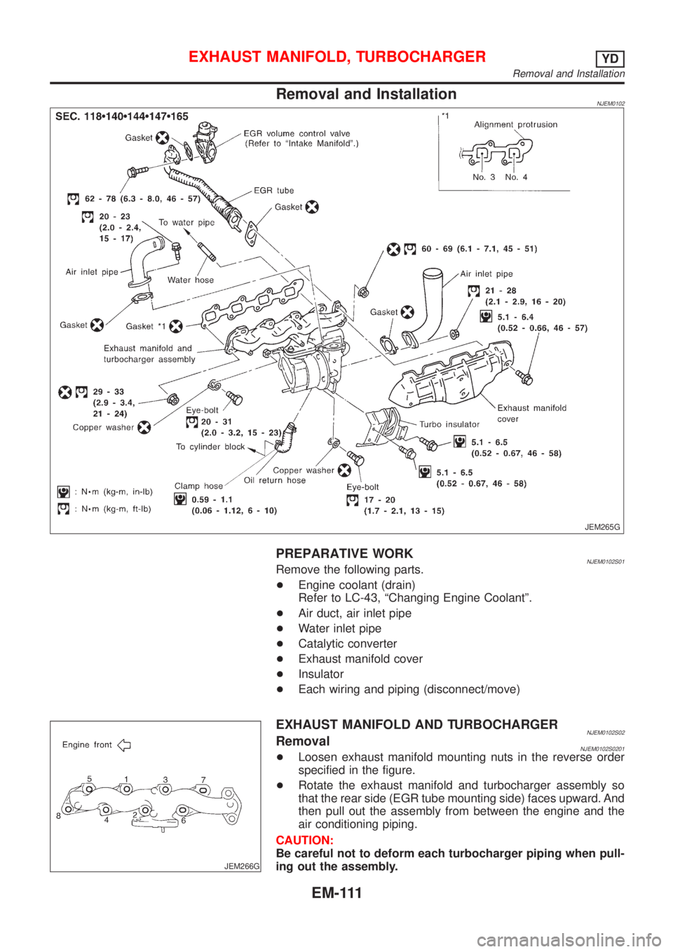
Removal and InstallationNJEM0102
JEM265G
PREPARATIVE WORKNJEM0102S01Remove the following parts.
+Engine coolant (drain)
Refer to LC-43, ªChanging Engine Coolantº.
+Air duct, air inlet pipe
+Water inlet pipe
+Catalytic converter
+Exhaust manifold cover
+Insulator
+Each wiring and piping (disconnect/move)
JEM266G
EXHAUST MANIFOLD AND TURBOCHARGERNJEM0102S02RemovalNJEM0102S0201+Loosen exhaust manifold mounting nuts in the reverse order
specified in the figure.
+Rotate the exhaust manifold and turbocharger assembly so
that the rear side (EGR tube mounting side) faces upward. And
then pull out the assembly from between the engine and the
air conditioning piping.
CAUTION:
Be careful not to deform each turbocharger piping when pull-
ing out the assembly.
EXHAUST MANIFOLD, TURBOCHARGERYD
Removal and Installation
EM-111
Page 190 of 2493
InstallationNJEM0102S0202+When a stud bolt is pulled out, tighten it to the following torque:
: 18 - 21 N´m (1.8 - 2.2 kg-m, 13 - 15 ft-lb)
+Tighten the exhaust manifold mounting nuts in the following
procedure:
a) Tighten the nuts in the order specified in the figure.
b) Re-tighten the nuts 1 to 4.
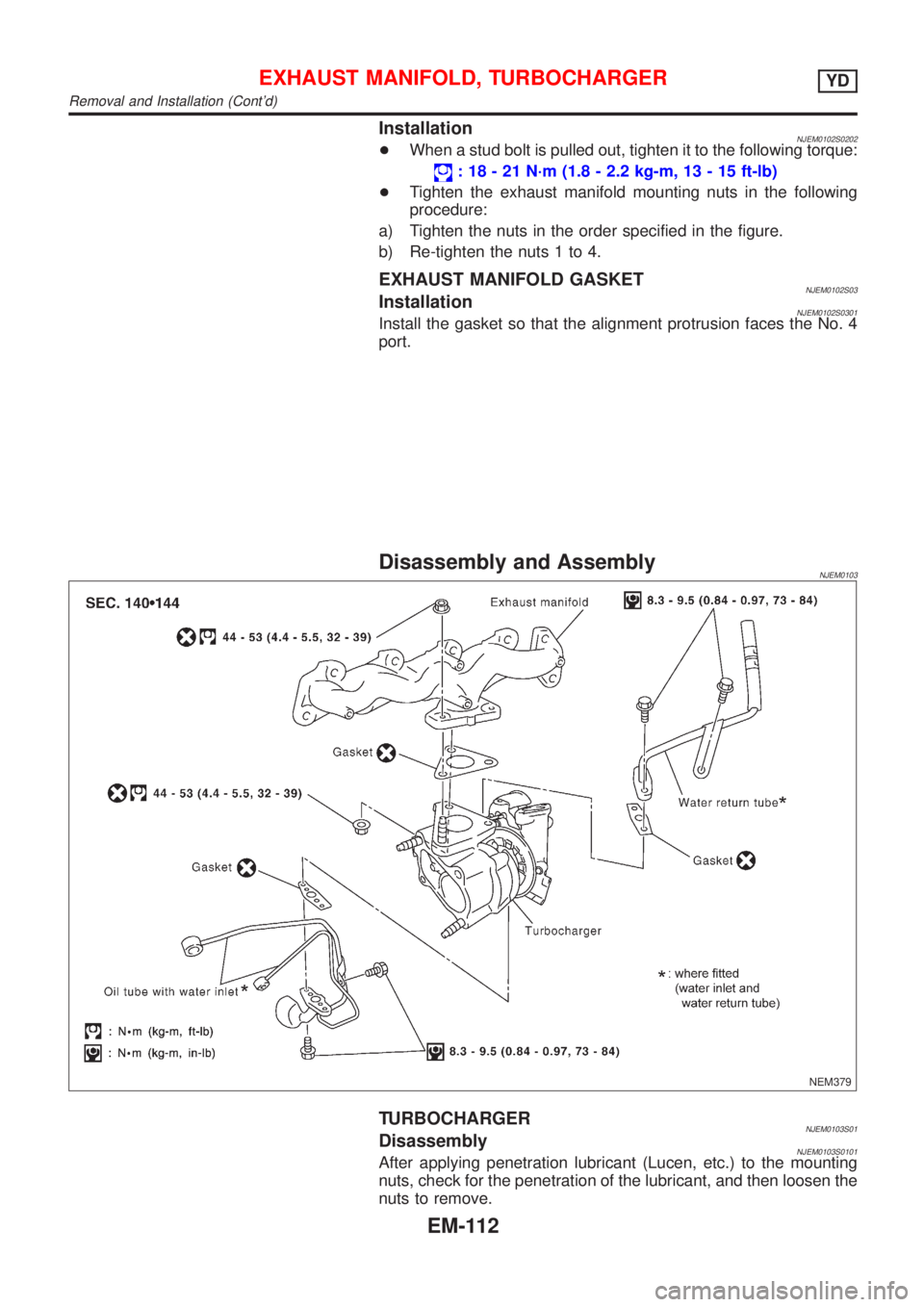
EXHAUST MANIFOLD GASKETNJEM0102S03InstallationNJEM0102S0301Install the gasket so that the alignment protrusion faces the No. 4
port.
Disassembly and AssemblyNJEM0103
NEM379
TURBOCHARGERNJEM0103S01DisassemblyNJEM0103S0101After applying penetration lubricant (Lucen, etc.) to the mounting
nuts, check for the penetration of the lubricant, and then loosen the
nuts to remove.
EXHAUST MANIFOLD, TURBOCHARGERYD
Removal and Installation (Cont'd)
EM-112