engine overheat NISSAN ALMERA N16 2001 Electronic User Guide
[x] Cancel search | Manufacturer: NISSAN, Model Year: 2001, Model line: ALMERA N16, Model: NISSAN ALMERA N16 2001Pages: 2493, PDF Size: 66.97 MB
Page 420 of 2493
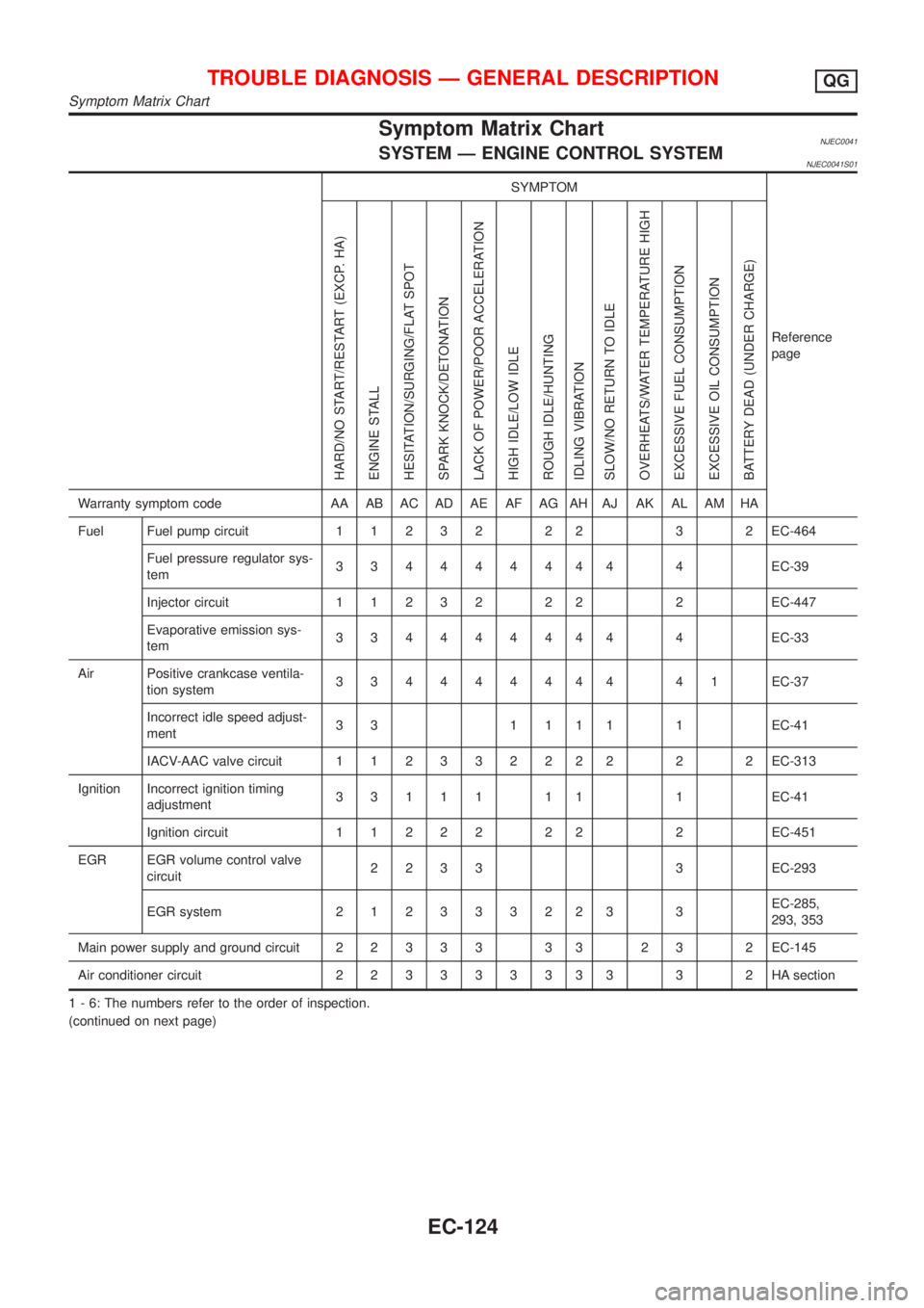
Symptom Matrix ChartNJEC0041SYSTEM Ð ENGINE CONTROL SYSTEMNJEC0041S01
SYMPTOM
Reference
page
HARD/NO START/RESTART (EXCP. HA)
ENGINE STALL
HESITATION/SURGING/FLAT SPOT
SPARK KNOCK/DETONATION
LACK OF POWER/POOR ACCELERATION
HIGH IDLE/LOW IDLE
ROUGH IDLE/HUNTING
IDLING VIBRATION
SLOW/NO RETURN TO IDLE
OVERHEATS/WATER TEMPERATURE HIGH
EXCESSIVE FUEL CONSUMPTION
EXCESSIVE OIL CONSUMPTION
BATTERY DEAD (UNDER CHARGE)
Warranty symptom code AA AB AC AD AE AF AG AH AJ AK AL AM HA
Fuel Fuel pump circuit11232 22 3 2EC-464
Fuel pressure regulator sys-
tem334444444 4EC-39
Injector circuit11232 22 2EC-447
Evaporative emission sys-
tem334444444 4EC-33
Air Positive crankcase ventila-
tion system334444444 41EC-37
Incorrect idle speed adjust-
ment3 3 1 1 1 1 1 EC-41
IACV-AAC valve circuit112332222 2 2EC-313
Ignition Incorrect ignition timing
adjustment33111 11 1EC-41
Ignition circuit11222 22 2EC-451
EGR EGR volume control valve
circuit2233 3EC-293
EGR system212333223 3EC-285,
293, 353
Main power supply and ground circuit22333 33 23 2EC-145
Air conditioner circuit223333333 3 2HAsection
1 - 6: The numbers refer to the order of inspection.
(continued on next page)
TROUBLE DIAGNOSIS Ð GENERAL DESCRIPTIONQG
Symptom Matrix Chart
EC-124
Page 421 of 2493
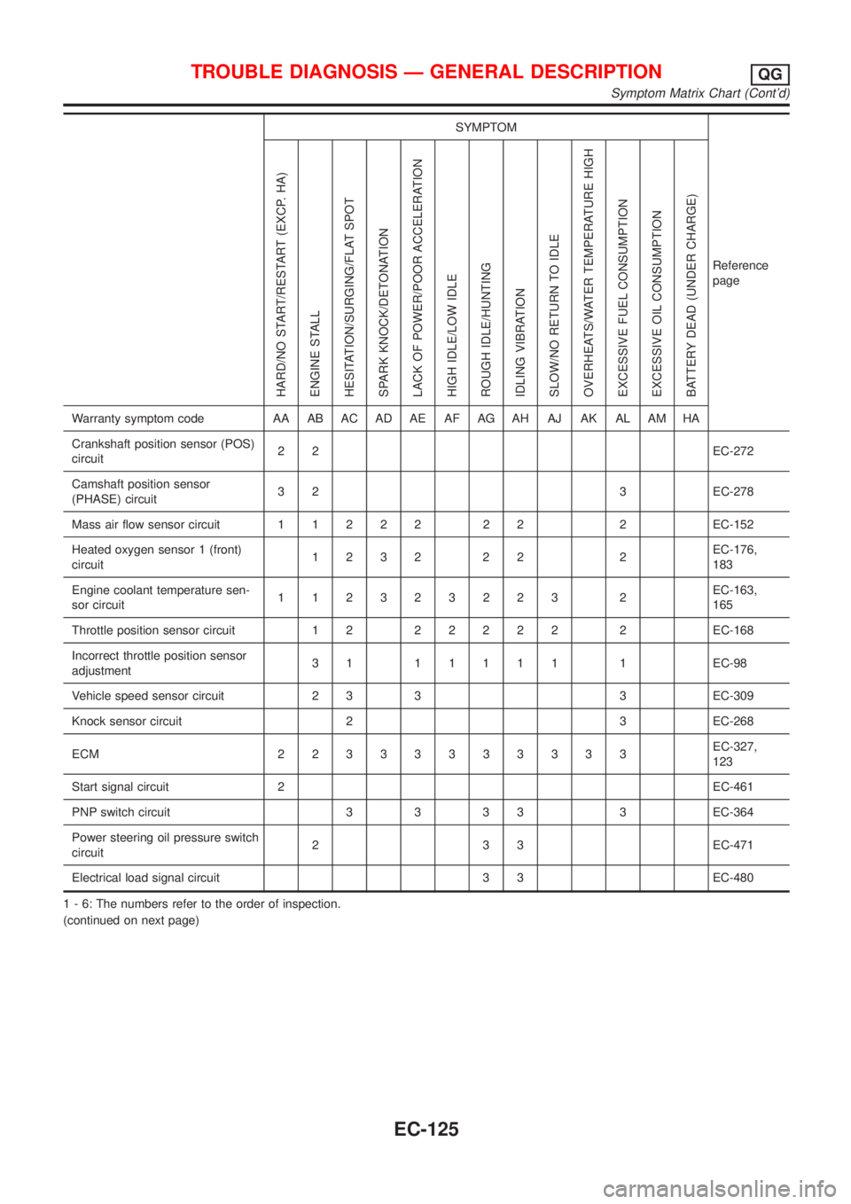
SYMPTOM
Reference
page
HARD/NO START/RESTART (EXCP. HA)
ENGINE STALL
HESITATION/SURGING/FLAT SPOT
SPARK KNOCK/DETONATION
LACK OF POWER/POOR ACCELERATION
HIGH IDLE/LOW IDLE
ROUGH IDLE/HUNTING
IDLING VIBRATION
SLOW/NO RETURN TO IDLE
OVERHEATS/WATER TEMPERATURE HIGH
EXCESSIVE FUEL CONSUMPTION
EXCESSIVE OIL CONSUMPTION
BATTERY DEAD (UNDER CHARGE)
Warranty symptom code AA AB AC AD AE AF AG AH AJ AK AL AM HA
Crankshaft position sensor (POS)
circuit22EC-272
Camshaft position sensor
(PHASE) circuit3 2 3 EC-278
Mass air flow sensor circuit11222 22 2EC-152
Heated oxygen sensor 1 (front)
circuit1232 22 2EC-176,
183
Engine coolant temperature sen-
sor circuit112323223 2EC-163,
165
Throttle position sensor circuit 1 222222 2EC-168
Incorrect throttle position sensor
adjustment31 11111 1EC-98
Vehicle speed sensor circuit 2 3 3 3 EC-309
Knock sensor circuit 2 3 EC-268
ECM 22333333333EC-327,
123
Start signal circuit 2EC-461
PNP switch circuit 3 3 3 3 3 EC-364
Power steering oil pressure switch
circuit2 3 3 EC-471
Electrical load signal circuit 3 3 EC-480
1 - 6: The numbers refer to the order of inspection.
(continued on next page)
TROUBLE DIAGNOSIS Ð GENERAL DESCRIPTIONQG
Symptom Matrix Chart (Cont'd)
EC-125
Page 422 of 2493
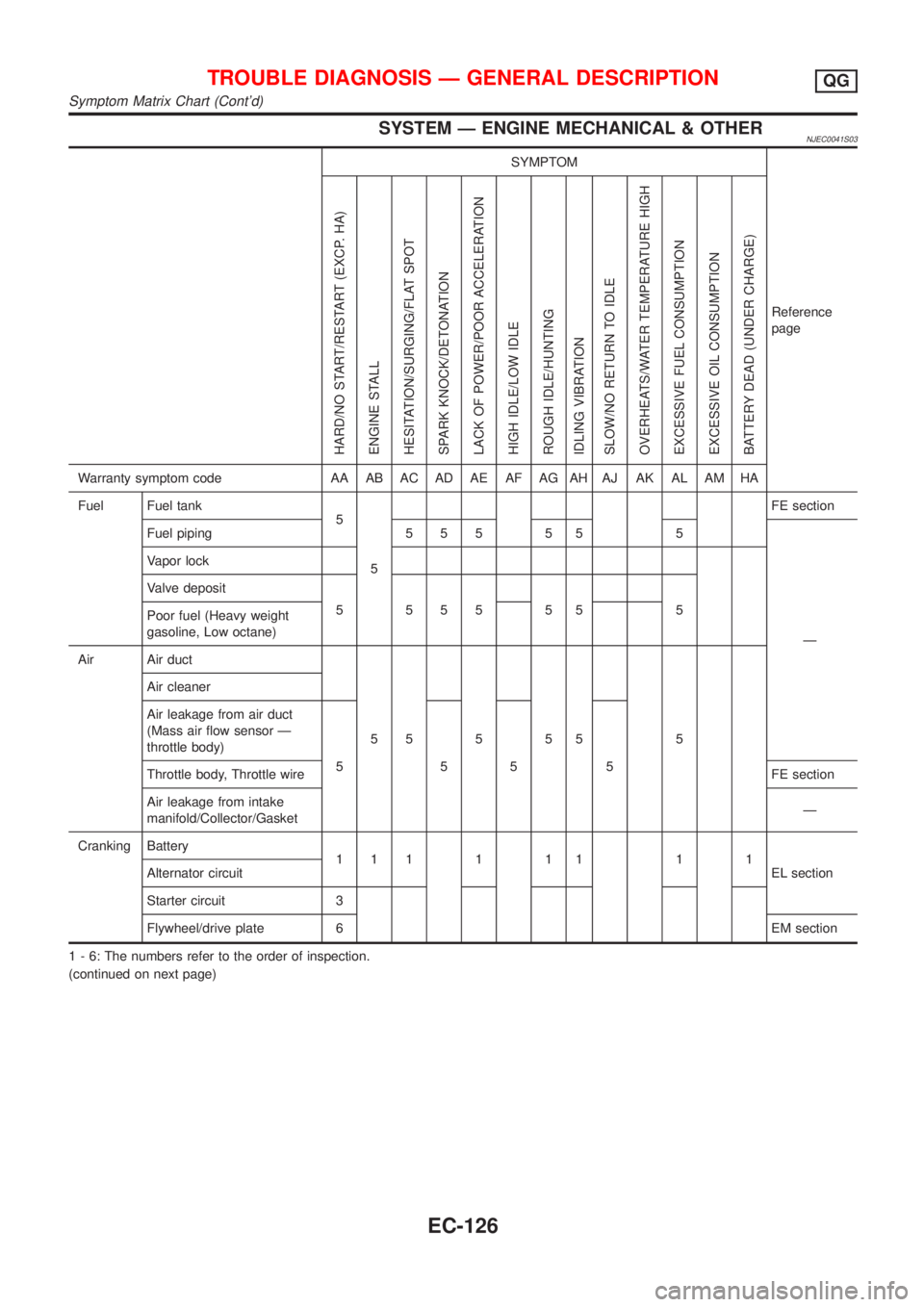
SYSTEM Ð ENGINE MECHANICAL & OTHERNJEC0041S03
SYMPTOM
Reference
page
HARD/NO START/RESTART (EXCP. HA)
ENGINE STALL
HESITATION/SURGING/FLAT SPOT
SPARK KNOCK/DETONATION
LACK OF POWER/POOR ACCELERATION
HIGH IDLE/LOW IDLE
ROUGH IDLE/HUNTING
IDLING VIBRATION
SLOW/NO RETURN TO IDLE
OVERHEATS/WATER TEMPERATURE HIGH
EXCESSIVE FUEL CONSUMPTION
EXCESSIVE OIL CONSUMPTION
BATTERY DEAD (UNDER CHARGE)
Warranty symptom code AA AB AC AD AE AF AG AH AJ AK AL AM HA
Fuel Fuel tank
5
5FE section
Fuel piping 5 5 5 5 5 5
Ð Vapor lock
Valve deposit
5 555 55 5
Poor fuel (Heavy weight
gasoline, Low octane)
Air Air duct
55555 5 Air cleaner
Air leakage from air duct
(Mass air flow sensor Ð
throttle body)
5555
Throttle body, Throttle wireFE section
Air leakage from intake
manifold/Collector/GasketÐ
Cranking Battery
111111 11
EL section Alternator circuit
Starter circuit 3
Flywheel/drive plate 6EM section
1 - 6: The numbers refer to the order of inspection.
(continued on next page)
TROUBLE DIAGNOSIS Ð GENERAL DESCRIPTIONQG
Symptom Matrix Chart (Cont'd)
EC-126
Page 423 of 2493
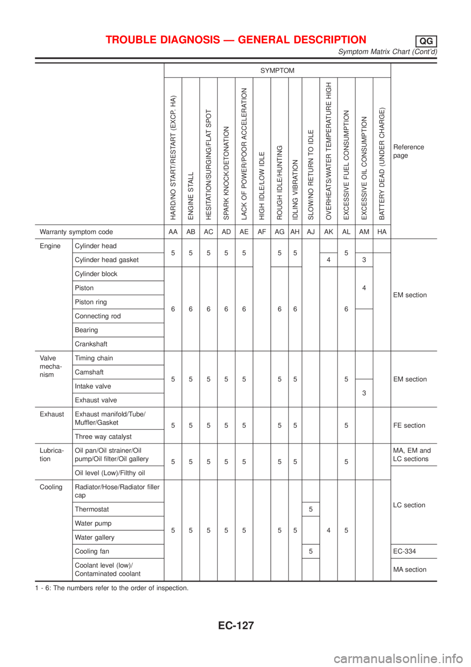
SYMPTOM
Reference
page
HARD/NO START/RESTART (EXCP. HA)
ENGINE STALL
HESITATION/SURGING/FLAT SPOT
SPARK KNOCK/DETONATION
LACK OF POWER/POOR ACCELERATION
HIGH IDLE/LOW IDLE
ROUGH IDLE/HUNTING
IDLING VIBRATION
SLOW/NO RETURN TO IDLE
OVERHEATS/WATER TEMPERATURE HIGH
EXCESSIVE FUEL CONSUMPTION
EXCESSIVE OIL CONSUMPTION
BATTERY DEAD (UNDER CHARGE)
Warranty symptom code AA AB AC AD AE AF AG AH AJ AK AL AM HA
Engine Cylinder head
55555 55 5
EM section Cylinder head gasket 4 3
Cylinder block
66666 66 64 Piston
Piston ring
Connecting rod
Bearing
Crankshaft
Valve
mecha-
nismTiming chain
55555 55 5 EMsection Camshaft
Intake valve
3
Exhaust valve
Exhaust Exhaust manifold/Tube/
Muffler/Gasket
55555 55 5 FEsection
Three way catalyst
Lubrica-
tionOil pan/Oil strainer/Oil
pump/Oil filter/Oil gallery
55555 55 5MA, EM and
LC sections
Oil level (Low)/Filthy oil
LC section Cooling Radiator/Hose/Radiator filler
cap
55555 55 45 Thermostat 5
Water pump
Water gallery
Cooling fan 5 EC-334
Coolant level (low)/
Contaminated coolantMA section
1 - 6: The numbers refer to the order of inspection.
TROUBLE DIAGNOSIS Ð GENERAL DESCRIPTIONQG
Symptom Matrix Chart (Cont'd)
EC-127
Page 558 of 2493
On Board Diagnosis LogicNJEC0202If a misfire occurs, the engine speed will fluctuate. If the fluctuation is detected by the crankshaft position sen-
sor (POS), the misfire is diagnosed.
Sensor Input Signal to ECM ECM function
Crankshaft position sensor (POS) Engine speed On board diagnosis of misfire
The misfire detection logic consists of the following two conditions.
1. One Trip Detection Logic (Three Way Catalyst Damage)
When a misfire is detected which will overheat and damage the three way catalyst, the MI will start blink-
ing; even during the first trip. In this condition, ECM monitors the misfire every 200 revolutions.
If the misfire frequency decreases to a level that will not damage the three way catalyst, the MI will change
from blinking to lighting up. (After the first trip detection, the MI will light up from engine starting. If a mis-
fire is detected that will cause three way catalyst damage, the MI will start blinking.)
2. Two Trip Detection Logic (Exhaust quality deterioration)
When a misfire that will not damage the three way catalyst (but will affect exhaust emission) occurs, the
MI will light up based on two trip detection logic. In this condition, ECM monitors the misfire for every 1,000
revolutions of the engine.
DTC No. Malfunction is detected when ... Check Items (Possible Cause)
P0300
0300+Multiple cylinders misfire.+Improper spark plug
+Insufficient compression
+Incorrect fuel pressure
+EGR volume control valve
+The injector circuit is open or shorted
+Injectors
+Intake air leak
+Insufficient ignition spark
+Lack of fuel
+Heated oxygen sensor 1 (front) P0301
0301+No. 1 cylinder misfires.
P0302
0302+No. 2 cylinder misfires.
P0303
0303+No. 3 cylinder misfires.
P0304
0304+No. 4 cylinder misfires.
SEF058Y
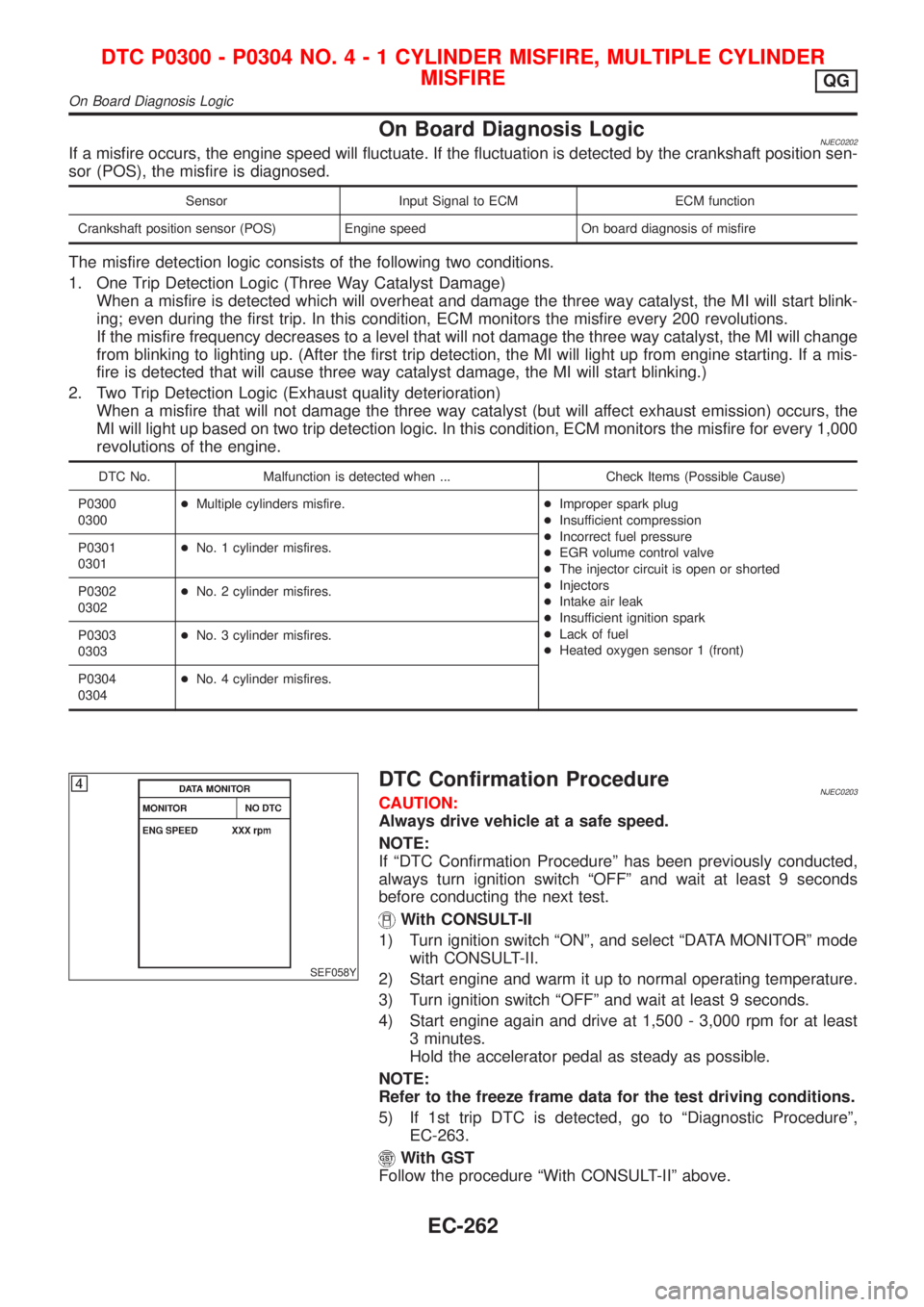
DTC Confirmation ProcedureNJEC0203CAUTION:
Always drive vehicle at a safe speed.
NOTE:
If ªDTC Confirmation Procedureº has been previously conducted,
always turn ignition switch ªOFFº and wait at least 9 seconds
before conducting the next test.
With CONSULT-II
1) Turn ignition switch ªONº, and select ªDATA MONITORº mode
with CONSULT-II.
2) Start engine and warm it up to normal operating temperature.
3) Turn ignition switch ªOFFº and wait at least 9 seconds.
4) Start engine again and drive at 1,500 - 3,000 rpm for at least
3 minutes.
Hold the accelerator pedal as steady as possible.
NOTE:
Refer to the freeze frame data for the test driving conditions.
5) If 1st trip DTC is detected, go to ªDiagnostic Procedureº,
EC-263.
With GST
Follow the procedure ªWith CONSULT-IIº above.
DTC P0300 - P0304 NO.4-1CYLINDER MISFIRE, MULTIPLE CYLINDER
MISFIRE
QG
On Board Diagnosis Logic
EC-262
Page 630 of 2493

System DescriptionNJEC0433COOLING FAN CONTROLNJEC0433S01
Sensor Input Signal to ECMECM func-
tionActuator
Vehicle speed sensor Vehicle speed
Cooling fan
controlCooling fan relay(s) Engine coolant temperature sensor Engine coolant temperature
Air conditioner switch Air conditioner ªONº signal
Ignition switch Start signal
Refrigerant pressure sensor Refrigerant pressure
The ECM controls the cooling fan corresponding to the vehicle speed, engine coolant temperature, refriger-
ant pressure, and air conditioner ON signal. The control system has ON-OFF control.
OPERATIONNJEC0433S02Engine coolant temperatures at which the cooling fan turns ªONº are indicated in the Table below.
Vehicle speed km/h (MPH)
Air conditioner switchHigh pressure of
refrigerant
kPa (bar, kg/cm
2, psi)Less than 50 (30) 50 - 80 (30 - 50) More than 80 (50)
ONMore than 1,680
(16.8, 17.14, 244)Always Always More than 95ÉC (203ÉF)
Less than 1,680
(16.8, 17.14, 244)Always More than 95ÉC (203ÉF) More than 95ÉC (203ÉF)
OFFMore than 100ÉC
(212ÉF)More than 95ÉC (203ÉF) More than 95ÉC (203ÉF)
CONSULT-II Reference Value in Data Monitor
Mode
NJEC0486Specification data are reference values.
MONITOR ITEM CONDITION SPECIFICATION
AIR COND SIG+Engine: After warming up, idle
the engineAir conditioner switch: OFF OFF
Air conditioner switch: ON
(Compressor operates)ON
COOLING FAN+After warming up engine, idle
the engine.
+Air conditioner switch: OFFEngine coolant temperature is less
than 100ÉC (212ÉF)OFF
Engine coolant temperature is
100ÉC (212ÉF) or moreON
DTC P1217 OVERHEAT (COOLING SYSTEM)QG
System Description
EC-334
Page 631 of 2493
ECM Terminals and Reference Value=NJEC0487Specification data are reference values and are measured between each terminal and ground.
CAUTION:
Do not use ECM ground terminals when measuring input/output voltage. Doing so may result in dam-
age to the ECM's transistor. Use a ground other than ECM terminals, such as the ground.
TERMI-
NAL
NO.WIRE
COLORITEM CONDITION DATA (DC Voltage)
13 LG/R Cooling fan relay[Engine is running]
+Cooling fan is not operatingBATTERY VOLTAGE
(11 - 14V)
[Engine is running]
+Cooling fan is operating0 - 0.6V
23 L/W Air conditioner switch[Engine is running]
+Both air conditioner switch and blower switch are
ªONº (Compressor operates)Approximately 0V
[Engine is running]
+Air conditioner switch is ªOFFºBATTERY VOLTAGE
(11 - 14V)
On Board Diagnosis LogicNJEC0572If the cooling fan or another component in the cooling system malfunctions, engine coolant temperature will
rise.
When the engine coolant temperature reaches an abnormally high temperature condition, a malfunction is
indicated.
DTC No. Malfunction is detected when ... Check Items (Possible Cause)
P1217
1217+The engine coolant temperature is extraordinary high,
even when the load is not heavy.+Harness or connectors
(The cooling fan circuit is open or shorted)
+Cooling fan
+Thermostat
+Improper ignition timing
+Engine coolant temperature sensor
+Blocked radiator
+Blocked front end (Improper fitting of nose mask)
+Crushed vehicle frontal area (Vehicle frontal is
collided but not repaired)
+Blocked air passage by improper installation of
front fog lamp or fog lamps.
+Improper mixture ratio of coolant
+Damaged bumper
For more information, refer to ªMAIN 12 CAUSES
OF OVERHEATINGº, EC-345.
CAUTION:
When a malfunction is indicated, be sure to replace the coolant following the procedure in the LC-17,
ªChanging Engine Coolantº. Also, replace the engine oil.
1) Fill radiator with coolant up to specified level with a filling speed of 2 liters per minute. Be sure to use
coolant with the proper mixture ratio. Refer to MA-22, ªAnti-freeze Coolant Mixture Ratioº, ªRECOM-
MENDED FLUIDS AND LUBRICANTSº.
2) After refilling coolant, run engine to ensure that no water-flow noise is emitted.
DTC P1217 OVERHEAT (COOLING SYSTEM)QG
ECM Terminals and Reference Value
EC-335
Page 632 of 2493
SEF621WA
SEF646X
SEC163BA
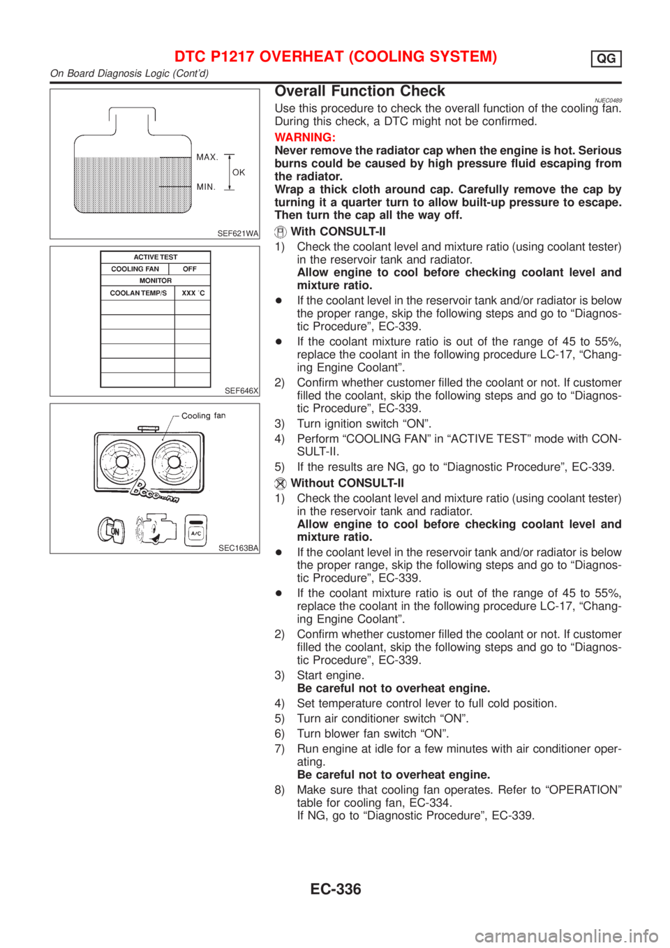
Overall Function CheckNJEC0489Use this procedure to check the overall function of the cooling fan.
During this check, a DTC might not be confirmed.
WARNING:
Never remove the radiator cap when the engine is hot. Serious
burns could be caused by high pressure fluid escaping from
the radiator.
Wrap a thick cloth around cap. Carefully remove the cap by
turning it a quarter turn to allow built-up pressure to escape.
Then turn the cap all the way off.
With CONSULT-II
1) Check the coolant level and mixture ratio (using coolant tester)
in the reservoir tank and radiator.
Allow engine to cool before checking coolant level and
mixture ratio.
+If the coolant level in the reservoir tank and/or radiator is below
the proper range, skip the following steps and go to ªDiagnos-
tic Procedureº, EC-339.
+If the coolant mixture ratio is out of the range of 45 to 55%,
replace the coolant in the following procedure LC-17, ªChang-
ing Engine Coolantº.
2) Confirm whether customer filled the coolant or not. If customer
filled the coolant, skip the following steps and go to ªDiagnos-
tic Procedureº, EC-339.
3) Turn ignition switch ªONº.
4) Perform ªCOOLING FANº in ªACTIVE TESTº mode with CON-
SULT-II.
5) If the results are NG, go to ªDiagnostic Procedureº, EC-339.
Without CONSULT-II
1) Check the coolant level and mixture ratio (using coolant tester)
in the reservoir tank and radiator.
Allow engine to cool before checking coolant level and
mixture ratio.
+If the coolant level in the reservoir tank and/or radiator is below
the proper range, skip the following steps and go to ªDiagnos-
tic Procedureº, EC-339.
+If the coolant mixture ratio is out of the range of 45 to 55%,
replace the coolant in the following procedure LC-17, ªChang-
ing Engine Coolantº.
2) Confirm whether customer filled the coolant or not. If customer
filled the coolant, skip the following steps and go to ªDiagnos-
tic Procedureº, EC-339.
3) Start engine.
Be careful not to overheat engine.
4) Set temperature control lever to full cold position.
5) Turn air conditioner switch ªONº.
6) Turn blower fan switch ªONº.
7) Run engine at idle for a few minutes with air conditioner oper-
ating.
Be careful not to overheat engine.
8) Make sure that cooling fan operates. Refer to ªOPERATIONº
table for cooling fan, EC-334.
If NG, go to ªDiagnostic Procedureº, EC-339.
DTC P1217 OVERHEAT (COOLING SYSTEM)QG
On Board Diagnosis Logic (Cont'd)
EC-336
Page 635 of 2493
Diagnostic ProcedureNJEC0491
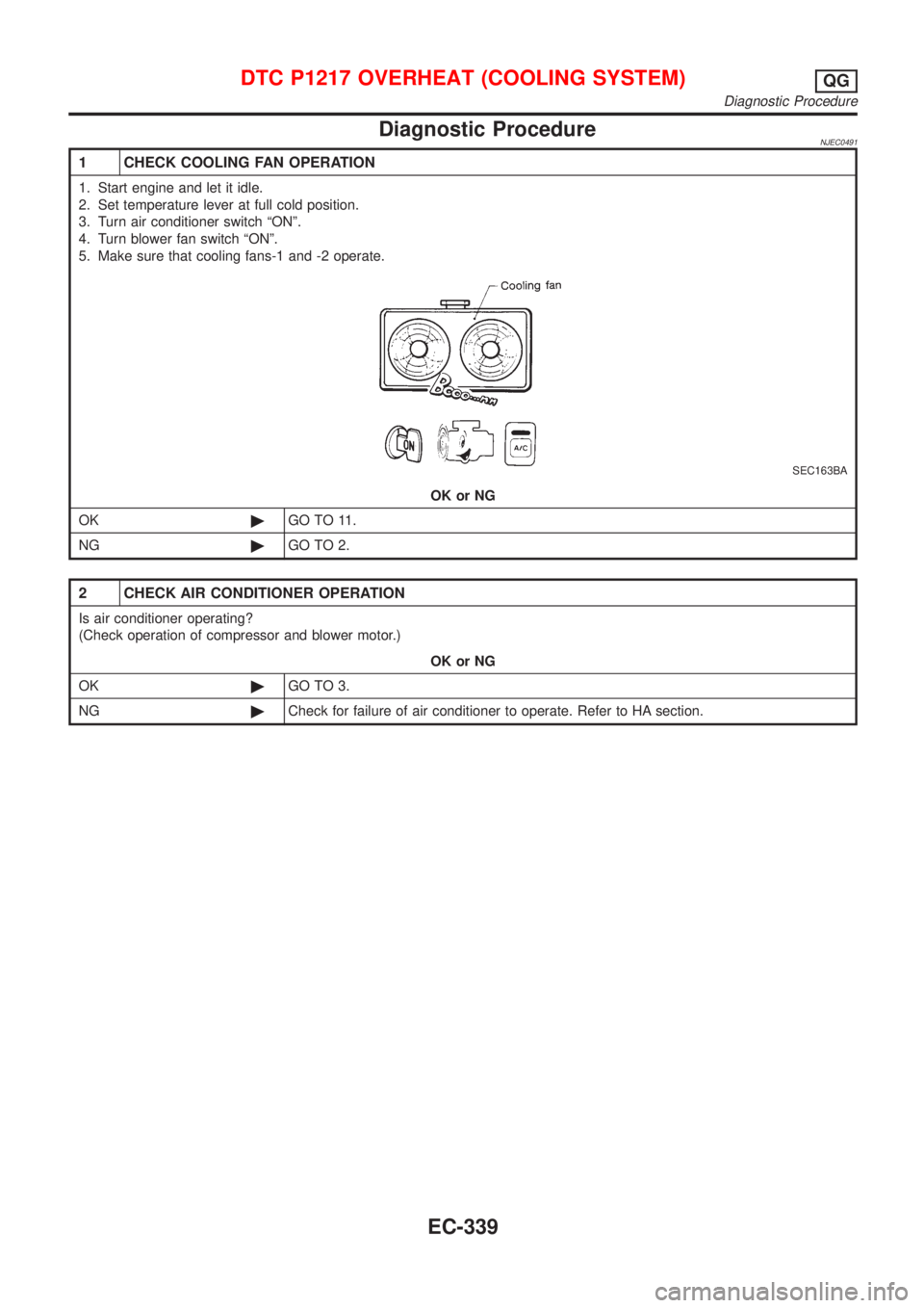
1 CHECK COOLING FAN OPERATION
1. Start engine and let it idle.
2. Set temperature lever at full cold position.
3. Turn air conditioner switch ªONº.
4. Turn blower fan switch ªONº.
5. Make sure that cooling fans-1 and -2 operate.
SEC163BA
OK or NG
OK©GO TO 11.
NG©GO TO 2.
2 CHECK AIR CONDITIONER OPERATION
Is air conditioner operating?
(Check operation of compressor and blower motor.)
OK or NG
OK©GO TO 3.
NG©Check for failure of air conditioner to operate. Refer to HA section.
DTC P1217 OVERHEAT (COOLING SYSTEM)QG
Diagnostic Procedure
EC-339
Page 639 of 2493
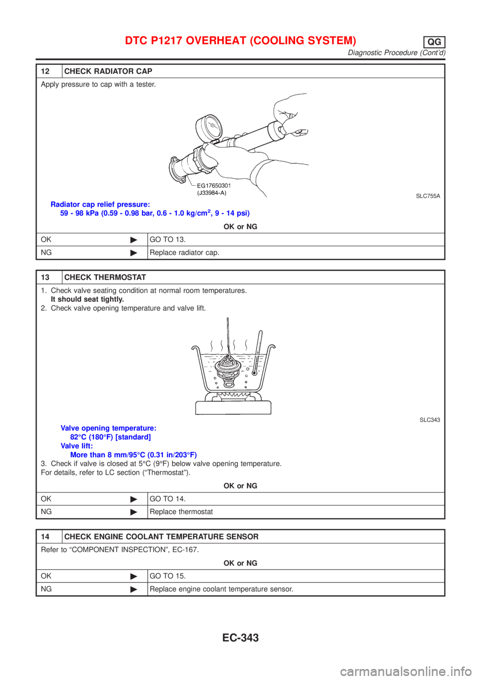
12 CHECK RADIATOR CAP
Apply pressure to cap with a tester.
SLC755A
Radiator cap relief pressure:
59 - 98 kPa (0.59 - 0.98 bar, 0.6 - 1.0 kg/cm2,9-14psi)
OK or NG
OK©GO TO 13.
NG©Replace radiator cap.
13 CHECK THERMOSTAT
1. Check valve seating condition at normal room temperatures.
It should seat tightly.
2. Check valve opening temperature and valve lift.
SLC343
Valve opening temperature:
82ÉC (180ÉF) [standard]
Valve lift:
More than 8 mm/95ÉC (0.31 in/203ÉF)
3. Check if valve is closed at 5ÉC (9ÉF) below valve opening temperature.
For details, refer to LC section (ªThermostatº).
OK or NG
OK©GO TO 14.
NG©Replace thermostat
14 CHECK ENGINE COOLANT TEMPERATURE SENSOR
Refer to ªCOMPONENT INSPECTIONº, EC-167.
OK or NG
OK©GO TO 15.
NG©Replace engine coolant temperature sensor.
DTC P1217 OVERHEAT (COOLING SYSTEM)QG
Diagnostic Procedure (Cont'd)
EC-343