service indicator NISSAN ALMERA N16 2001 Electronic User Guide
[x] Cancel search | Manufacturer: NISSAN, Model Year: 2001, Model line: ALMERA N16, Model: NISSAN ALMERA N16 2001Pages: 2493, PDF Size: 66.97 MB
Page 312 of 2493
Supplemental Restraint System (SRS) ªAIR
BAGº and ªSEAT BELT PRE-TENSIONERº
NJEC0002The Supplemental Restraint System such as ªAIR BAGº and ªSEAT BELT PRE-TENSIONERº used along with
a seat belt, helps to reduce the risk or severity of injury to the driver and front passenger for certain types of
collision. The SRS system composition which is available to NISSAN MODEL N16 is as follows (The compo-
sition varies according to the destination and optional equipment.):
+For a frontal collision
The Supplemental Restraint System consists of driver air bag module (located in the center of the steer-
ing wheel), front passenger air bag module (located on the instrument panel on passenger side), front seat
belt pre-tensioners, a diagnoses sensor unit, warning lamp, wiring harness and spiral cable.
+For a side collision
The Supplemental Restraint System consists of front side air bag module (located in the outer side of front
seat), side air bag (satellite) sensor, diagnoses sensor unit (one of components of air bags for a frontal
collision), wiring harness, warning lamp (one of components of air bags for a frontal collision).
Information necessary to service the system safely is included in theRS sectionof this Service Manual.
WARNING:
+To avoid rendering the SRS inoperative, which could increase the risk of personal injury or death
in the event of a collision which would result in air bag inflation, all maintenance should be per-
formed by an authorized NISSAN dealer.
+Improper maintenance, including incorrect removal and installation of the SRS, can lead to per-
sonal injury caused by unintentional activation of the system. For removal of Spiral Cable and Air
Bag Module, see the RS section.
+Do not use electrical test equipment on any circuit related to the SRS unless instructed to in this
Service Manual. SRS wiring harness can be identified by yellow harness connector.
Precautions for On Board Diagnostic (OBD)
System of Engine and A/T
NJEC0003The ECM has an on board diagnostic system. It will light up the malfunction indicator (MI) to warn the driver
of a malfunction causing emission deterioration.
CAUTION:
+Be sure to turn the ignition switch ªOFFº and disconnect the negative battery terminal before any
repair or inspection work. The open/short circuit of related switches, sensors, solenoid valves, etc.
will cause the MI to light up.
+Be sure to connect and lock the connectors securely after work. A loose (unlocked) connector will
cause the MI to light up due to the open circuit. (Be sure the connector is free from water, grease,
dirt, bent terminals, etc.)
+Certain systems and components, especially those related to OBD, may use a new style slide-
locking type harness connector.
For description and how to disconnect, refer to EL section, ªDescriptionº, ªHARNESS CONNEC-
TORº.
+Be sure to route and secure the harnesses properly after work. The interference of the harness with
a bracket, etc. may cause the MI to light up due to the short circuit.
+Be sure to connect rubber tubes properly after work. A misconnected or disconnected rubber tube
may cause the MI to light up due to the malfunction of fuel injection system, etc.
+Be sure to erase the unnecessary malfunction information (repairs completed) from the ECM and
TCM (Transmission Control Module) before returning the vehicle to the customer.
PRECAUTIONSQG
Supplemental Restraint System (SRS) ªAIR BAGº and ªSEAT BELT PRE-TENSIONERº
EC-16
Page 341 of 2493
Inspection ProcedureNJEC0593
1 INSPECTION START
1. Visually check the following:
+Air cleaner clogging
+Hoses and ducts for leaks
+EGR valve operation
+Electrical connectors
+Gasket
+Throttle valve and throttle position sensor operation
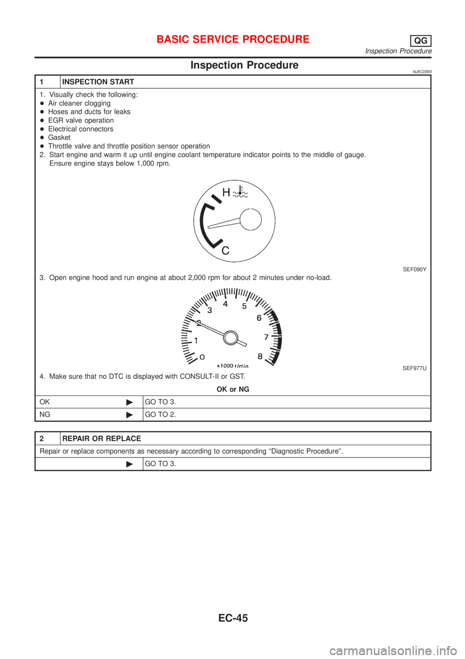
2. Start engine and warm it up until engine coolant temperature indicator points to the middle of gauge.
Ensure engine stays below 1,000 rpm.
SEF090Y
3. Open engine hood and run engine at about 2,000 rpm for about 2 minutes under no-load.
SEF977U
4. Make sure that no DTC is displayed with CONSULT-II or GST.
OK or NG
OK©GO TO 3.
NG©GO TO 2.
2 REPAIR OR REPLACE
Repair or replace components as necessary according to corresponding ªDiagnostic Procedureº.
©GO TO 3.
BASIC SERVICE PROCEDUREQG
Inspection Procedure
EC-45
Page 349 of 2493
26 CHECK ªCOº %
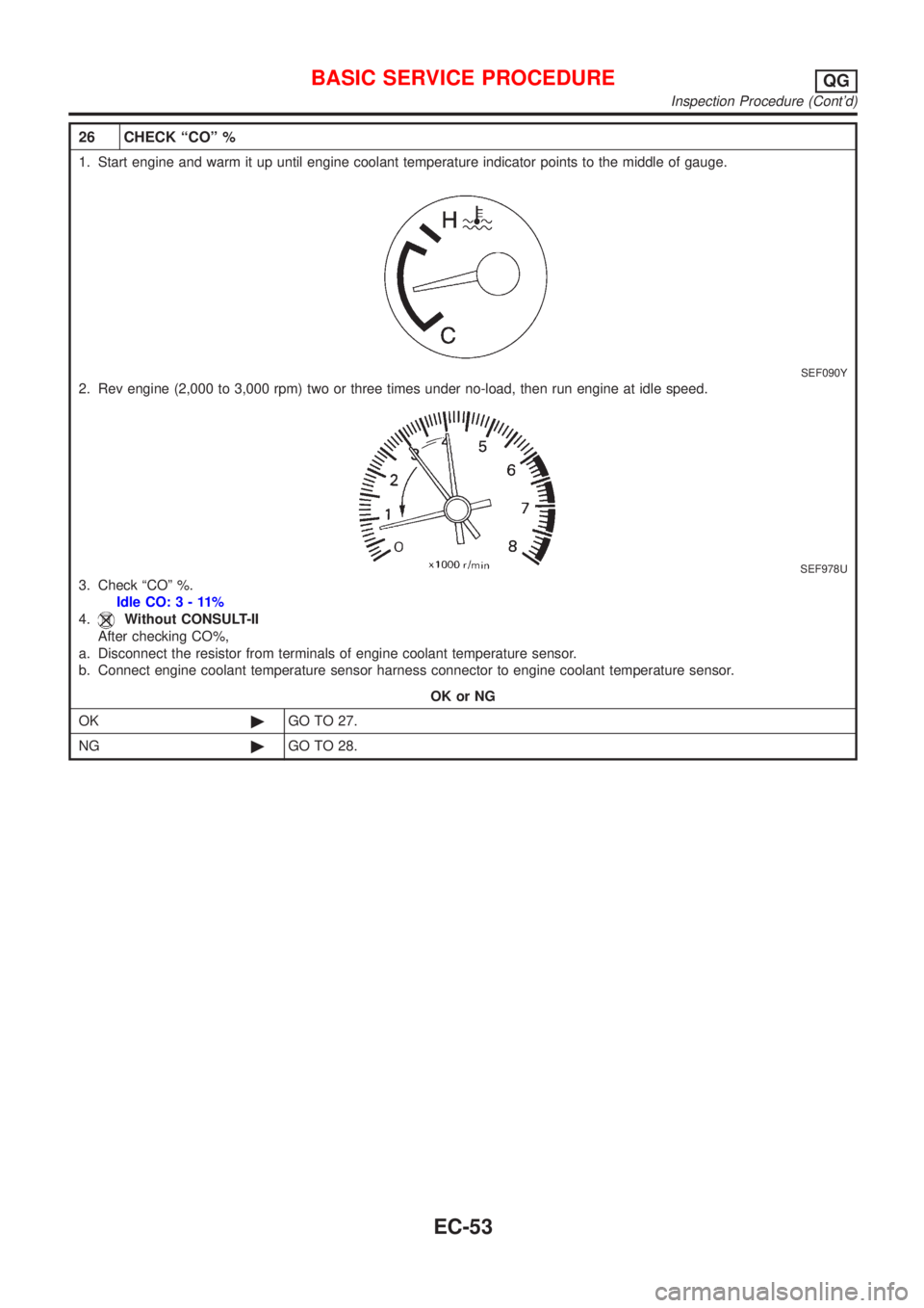
1. Start engine and warm it up until engine coolant temperature indicator points to the middle of gauge.
SEF090Y
2. Rev engine (2,000 to 3,000 rpm) two or three times under no-load, then run engine at idle speed.
SEF978U
3. Check ªCOº %.
Idle CO:3-11%
4.
Without CONSULT-II
After checking CO%,
a. Disconnect the resistor from terminals of engine coolant temperature sensor.
b. Connect engine coolant temperature sensor harness connector to engine coolant temperature sensor.
OK or NG
OK©GO TO 27.
NG©GO TO 28.
BASIC SERVICE PROCEDUREQG
Inspection Procedure (Cont'd)
EC-53
Page 810 of 2493
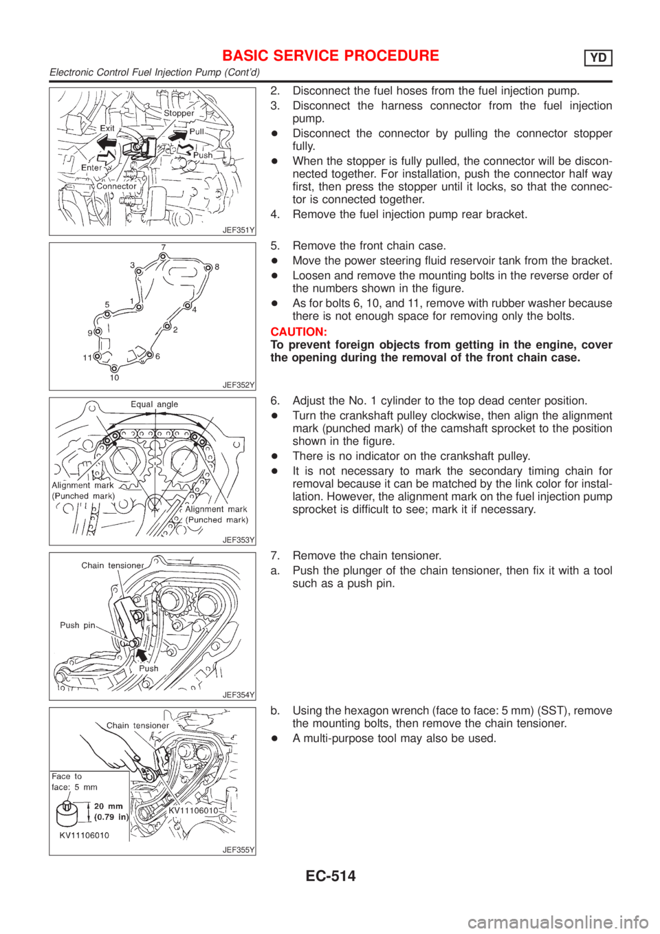
JEF351Y
2. Disconnect the fuel hoses from the fuel injection pump.
3. Disconnect the harness connector from the fuel injection
pump.
+Disconnect the connector by pulling the connector stopper
fully.
+When the stopper is fully pulled, the connector will be discon-
nected together. For installation, push the connector half way
first, then press the stopper until it locks, so that the connec-
tor is connected together.
4. Remove the fuel injection pump rear bracket.
JEF352Y
5. Remove the front chain case.
+Move the power steering fluid reservoir tank from the bracket.
+Loosen and remove the mounting bolts in the reverse order of
the numbers shown in the figure.
+As for bolts 6, 10, and 11, remove with rubber washer because
there is not enough space for removing only the bolts.
CAUTION:
To prevent foreign objects from getting in the engine, cover
the opening during the removal of the front chain case.
JEF353Y
6. Adjust the No. 1 cylinder to the top dead center position.
+Turn the crankshaft pulley clockwise, then align the alignment
mark (punched mark) of the camshaft sprocket to the position
shown in the figure.
+There is no indicator on the crankshaft pulley.
+It is not necessary to mark the secondary timing chain for
removal because it can be matched by the link color for instal-
lation. However, the alignment mark on the fuel injection pump
sprocket is difficult to see; mark it if necessary.
JEF354Y
7. Remove the chain tensioner.
a. Push the plunger of the chain tensioner, then fix it with a tool
such as a push pin.
JEF355Y
b. Using the hexagon wrench (face to face: 5 mm) (SST), remove
the mounting bolts, then remove the chain tensioner.
+A multi-purpose tool may also be used.
BASIC SERVICE PROCEDUREYD
Electronic Control Fuel Injection Pump (Cont'd)
EC-514
Page 1185 of 2493
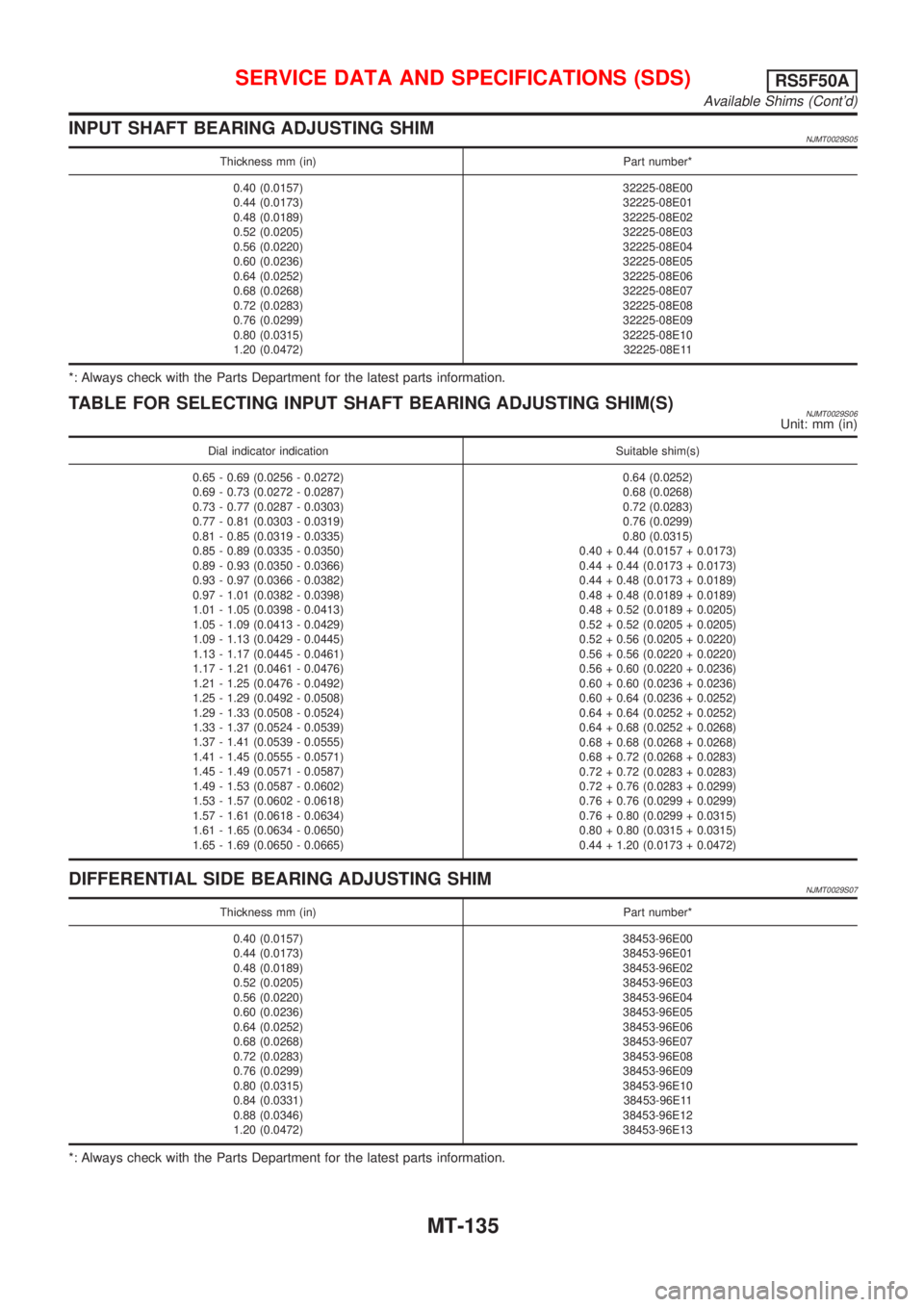
INPUT SHAFT BEARING ADJUSTING SHIMNJMT0029S05
Thickness mm (in) Part number*
0.40 (0.0157)
0.44 (0.0173)
0.48 (0.0189)
0.52 (0.0205)
0.56 (0.0220)
0.60 (0.0236)
0.64 (0.0252)
0.68 (0.0268)
0.72 (0.0283)
0.76 (0.0299)
0.80 (0.0315)
1.20 (0.0472)32225-08E00
32225-08E01
32225-08E02
32225-08E03
32225-08E04
32225-08E05
32225-08E06
32225-08E07
32225-08E08
32225-08E09
32225-08E10
32225-08E11
*: Always check with the Parts Department for the latest parts information.
TABLE FOR SELECTING INPUT SHAFT BEARING ADJUSTING SHIM(S)NJMT0029S06Unit: mm (in)
Dial indicator indication Suitable shim(s)
0.65 - 0.69 (0.0256 - 0.0272)
0.69 - 0.73 (0.0272 - 0.0287)
0.73 - 0.77 (0.0287 - 0.0303)
0.77 - 0.81 (0.0303 - 0.0319)
0.81 - 0.85 (0.0319 - 0.0335)
0.85 - 0.89 (0.0335 - 0.0350)
0.89 - 0.93 (0.0350 - 0.0366)
0.93 - 0.97 (0.0366 - 0.0382)
0.97 - 1.01 (0.0382 - 0.0398)
1.01 - 1.05 (0.0398 - 0.0413)
1.05 - 1.09 (0.0413 - 0.0429)
1.09 - 1.13 (0.0429 - 0.0445)
1.13 - 1.17 (0.0445 - 0.0461)
1.17 - 1.21 (0.0461 - 0.0476)
1.21 - 1.25 (0.0476 - 0.0492)
1.25 - 1.29 (0.0492 - 0.0508)
1.29 - 1.33 (0.0508 - 0.0524)
1.33 - 1.37 (0.0524 - 0.0539)
1.37 - 1.41 (0.0539 - 0.0555)
1.41 - 1.45 (0.0555 - 0.0571)
1.45 - 1.49 (0.0571 - 0.0587)
1.49 - 1.53 (0.0587 - 0.0602)
1.53 - 1.57 (0.0602 - 0.0618)
1.57 - 1.61 (0.0618 - 0.0634)
1.61 - 1.65 (0.0634 - 0.0650)
1.65 - 1.69 (0.0650 - 0.0665)0.64 (0.0252)
0.68 (0.0268)
0.72 (0.0283)
0.76 (0.0299)
0.80 (0.0315)
0.40 + 0.44 (0.0157 + 0.0173)
0.44 + 0.44 (0.0173 + 0.0173)
0.44 + 0.48 (0.0173 + 0.0189)
0.48 + 0.48 (0.0189 + 0.0189)
0.48 + 0.52 (0.0189 + 0.0205)
0.52 + 0.52 (0.0205 + 0.0205)
0.52 + 0.56 (0.0205 + 0.0220)
0.56 + 0.56 (0.0220 + 0.0220)
0.56 + 0.60 (0.0220 + 0.0236)
0.60 + 0.60 (0.0236 + 0.0236)
0.60 + 0.64 (0.0236 + 0.0252)
0.64 + 0.64 (0.0252 + 0.0252)
0.64 + 0.68 (0.0252 + 0.0268)
0.68 + 0.68 (0.0268 + 0.0268)
0.68 + 0.72 (0.0268 + 0.0283)
0.72 + 0.72 (0.0283 + 0.0283)
0.72 + 0.76 (0.0283 + 0.0299)
0.76 + 0.76 (0.0299 + 0.0299)
0.76 + 0.80 (0.0299 + 0.0315)
0.80 + 0.80 (0.0315 + 0.0315)
0.44 + 1.20 (0.0173 + 0.0472)
DIFFERENTIAL SIDE BEARING ADJUSTING SHIMNJMT0029S07
Thickness mm (in) Part number*
0.40 (0.0157)
0.44 (0.0173)
0.48 (0.0189)
0.52 (0.0205)
0.56 (0.0220)
0.60 (0.0236)
0.64 (0.0252)
0.68 (0.0268)
0.72 (0.0283)
0.76 (0.0299)
0.80 (0.0315)
0.84 (0.0331)
0.88 (0.0346)
1.20 (0.0472)38453-96E00
38453-96E01
38453-96E02
38453-96E03
38453-96E04
38453-96E05
38453-96E06
38453-96E07
38453-96E08
38453-96E09
38453-96E10
38453-96E11
38453-96E12
38453-96E13
*: Always check with the Parts Department for the latest parts information.
SERVICE DATA AND SPECIFICATIONS (SDS)RS5F50A
Available Shims (Cont'd)
MT-135
Page 1186 of 2493
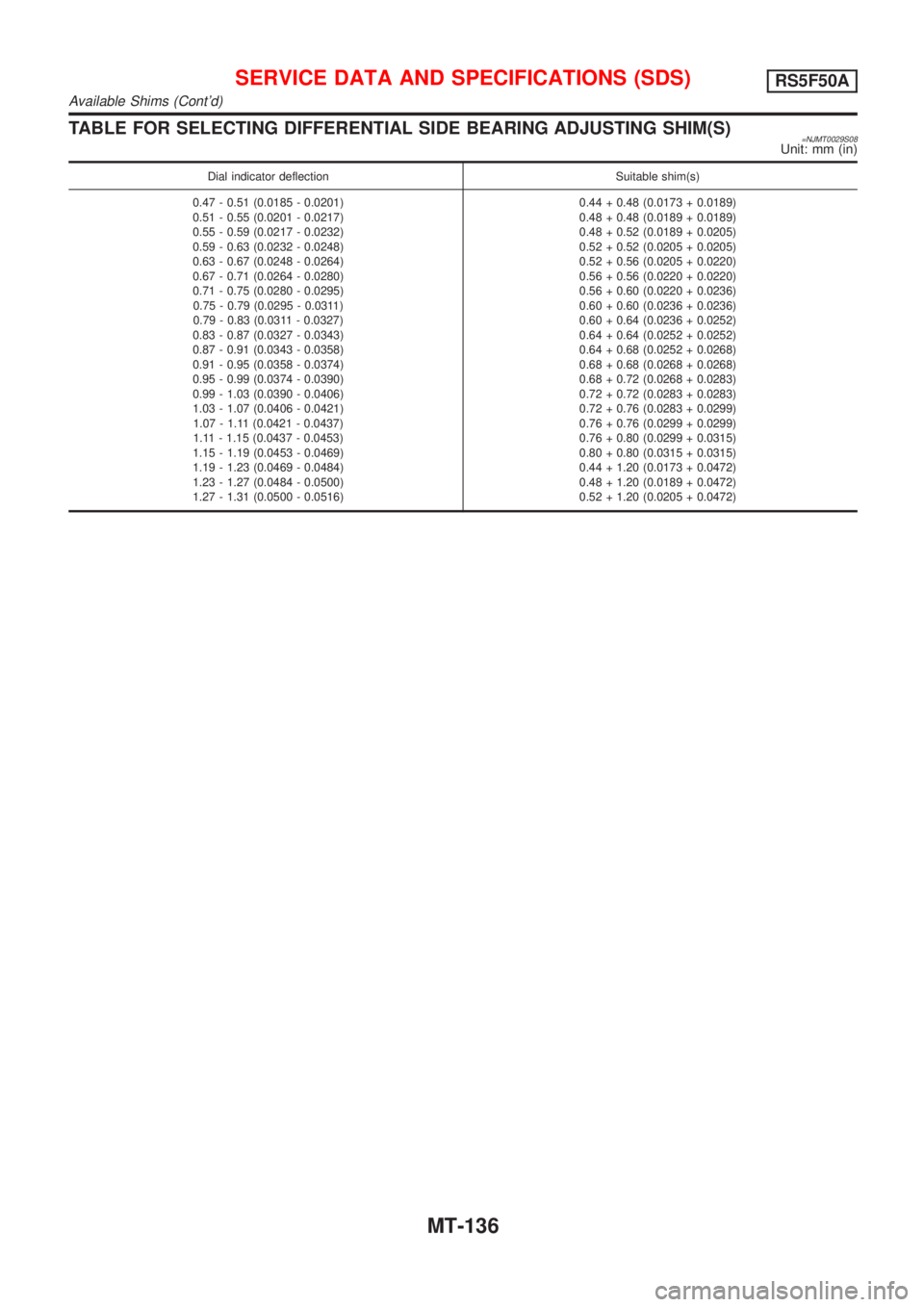
TABLE FOR SELECTING DIFFERENTIAL SIDE BEARING ADJUSTING SHIM(S)=NJMT0029S08Unit: mm (in)
Dial indicator deflection Suitable shim(s)
0.47 - 0.51 (0.0185 - 0.0201)
0.51 - 0.55 (0.0201 - 0.0217)
0.55 - 0.59 (0.0217 - 0.0232)
0.59 - 0.63 (0.0232 - 0.0248)
0.63 - 0.67 (0.0248 - 0.0264)
0.67 - 0.71 (0.0264 - 0.0280)
0.71 - 0.75 (0.0280 - 0.0295)
0.75 - 0.79 (0.0295 - 0.0311)
0.79 - 0.83 (0.0311 - 0.0327)
0.83 - 0.87 (0.0327 - 0.0343)
0.87 - 0.91 (0.0343 - 0.0358)
0.91 - 0.95 (0.0358 - 0.0374)
0.95 - 0.99 (0.0374 - 0.0390)
0.99 - 1.03 (0.0390 - 0.0406)
1.03 - 1.07 (0.0406 - 0.0421)
1.07 - 1.11 (0.0421 - 0.0437)
1.11 - 1.15 (0.0437 - 0.0453)
1.15 - 1.19 (0.0453 - 0.0469)
1.19 - 1.23 (0.0469 - 0.0484)
1.23 - 1.27 (0.0484 - 0.0500)
1.27 - 1.31 (0.0500 - 0.0516)0.44 + 0.48 (0.0173 + 0.0189)
0.48 + 0.48 (0.0189 + 0.0189)
0.48 + 0.52 (0.0189 + 0.0205)
0.52 + 0.52 (0.0205 + 0.0205)
0.52 + 0.56 (0.0205 + 0.0220)
0.56 + 0.56 (0.0220 + 0.0220)
0.56 + 0.60 (0.0220 + 0.0236)
0.60 + 0.60 (0.0236 + 0.0236)
0.60 + 0.64 (0.0236 + 0.0252)
0.64 + 0.64 (0.0252 + 0.0252)
0.64 + 0.68 (0.0252 + 0.0268)
0.68 + 0.68 (0.0268 + 0.0268)
0.68 + 0.72 (0.0268 + 0.0283)
0.72 + 0.72 (0.0283 + 0.0283)
0.72 + 0.76 (0.0283 + 0.0299)
0.76 + 0.76 (0.0299 + 0.0299)
0.76 + 0.80 (0.0299 + 0.0315)
0.80 + 0.80 (0.0315 + 0.0315)
0.44 + 1.20 (0.0173 + 0.0472)
0.48 + 1.20 (0.0189 + 0.0472)
0.52 + 1.20 (0.0205 + 0.0472)
SERVICE DATA AND SPECIFICATIONS (SDS)RS5F50A
Available Shims (Cont'd)
MT-136
Page 1187 of 2493
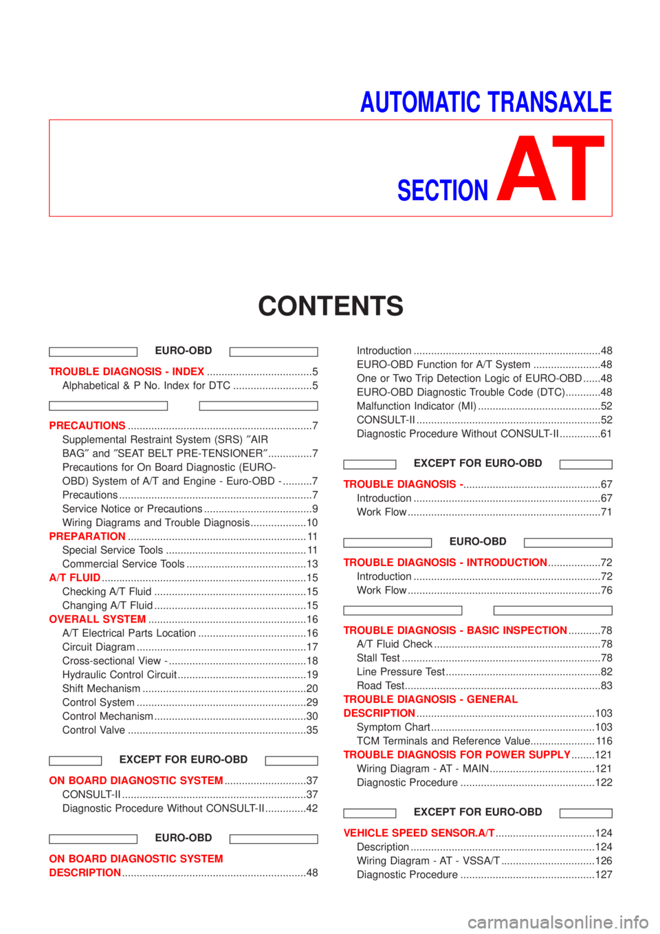
AUTOMATIC TRANSAXLE
SECTION
AT
CONTENTS
EURO-OBD
TROUBLE DIAGNOSIS - INDEX....................................5
Alphabetical & P No. Index for DTC ...........................5
PRECAUTIONS...............................................................7
Supplemental Restraint System (SRS)²AIR
BAG²and²SEAT BELT PRE-TENSIONER²...............7
Precautions for On Board Diagnostic (EURO-
OBD) System of A/T and Engine - Euro-OBD - ..........7
Precautions ..................................................................7
Service Notice or Precautions .....................................9
Wiring Diagrams and Trouble Diagnosis ...................10
PREPARATION............................................................. 11
Special Service Tools ................................................ 11
Commercial Service Tools .........................................13
A/T FLUID......................................................................15
Checking A/T Fluid ....................................................15
Changing A/T Fluid ....................................................15
OVERALL SYSTEM......................................................16
A/T Electrical Parts Location .....................................16
Circuit Diagram ..........................................................17
Cross-sectional View - ...............................................18
Hydraulic Control Circuit ............................................19
Shift Mechanism ........................................................20
Control System ..........................................................29
Control Mechanism ....................................................30
Control Valve .............................................................35
EXCEPT FOR EURO-OBD
ON BOARD DIAGNOSTIC SYSTEM............................37
CONSULT-II ...............................................................37
Diagnostic Procedure Without CONSULT-II ..............42
EURO-OBD
ON BOARD DIAGNOSTIC SYSTEM
DESCRIPTION...............................................................48Introduction ................................................................48
EURO-OBD Function for A/T System .......................48
One or Two Trip Detection Logic of EURO-OBD ......48
EURO-OBD Diagnostic Trouble Code (DTC)............48
Malfunction Indicator (MI) ..........................................52
CONSULT-II ...............................................................52
Diagnostic Procedure Without CONSULT-II ..............61
EXCEPT FOR EURO-OBD
TROUBLE DIAGNOSIS -...............................................67
Introduction ................................................................67
Work Flow ..................................................................71
EURO-OBD
TROUBLE DIAGNOSIS - INTRODUCTION..................72
Introduction ................................................................72
Work Flow ..................................................................76
TROUBLE DIAGNOSIS - BASIC INSPECTION...........78
A/T Fluid Check .........................................................78
Stall Test ....................................................................78
Line Pressure Test .....................................................82
Road Test...................................................................83
TROUBLE DIAGNOSIS - GENERAL
DESCRIPTION.............................................................103
Symptom Chart ........................................................103
TCM Terminals and Reference Value...................... 116
TROUBLE DIAGNOSIS FOR POWER SUPPLY........121
Wiring Diagram - AT - MAIN ....................................121
Diagnostic Procedure ..............................................122
EXCEPT FOR EURO-OBD
VEHICLE SPEED SENSOR.A/T..................................124
Description ...............................................................124
Wiring Diagram - AT - VSSA/T ................................126
Diagnostic Procedure ..............................................127
Page 1189 of 2493
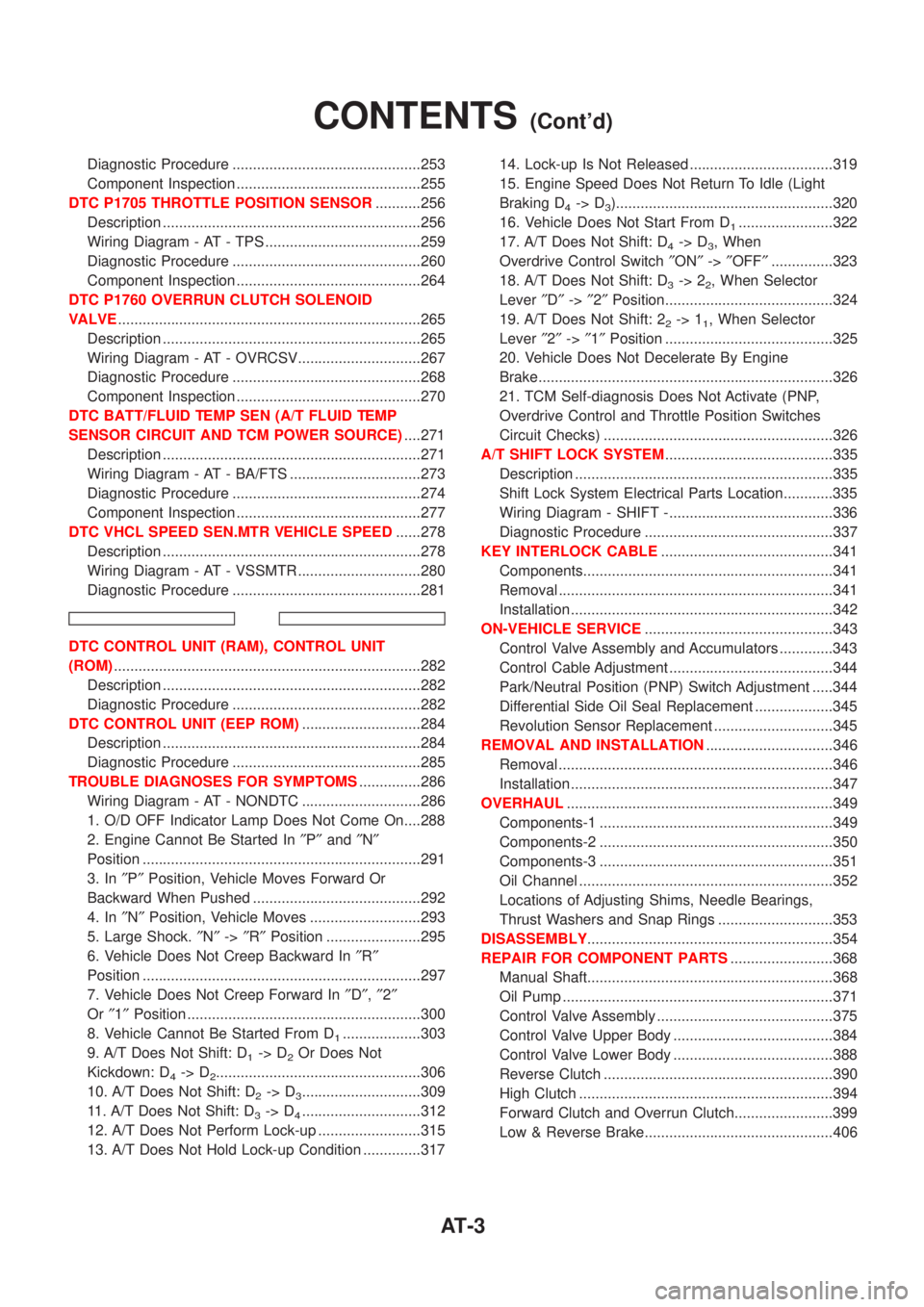
Diagnostic Procedure ..............................................253
Component Inspection .............................................255
DTC P1705 THROTTLE POSITION SENSOR...........256
Description ...............................................................256
Wiring Diagram - AT - TPS ......................................259
Diagnostic Procedure ..............................................260
Component Inspection .............................................264
DTC P1760 OVERRUN CLUTCH SOLENOID
VALVE..........................................................................265
Description ...............................................................265
Wiring Diagram - AT - OVRCSV..............................267
Diagnostic Procedure ..............................................268
Component Inspection .............................................270
DTC BATT/FLUID TEMP SEN (A/T FLUID TEMP
SENSOR CIRCUIT AND TCM POWER SOURCE)....271
Description ...............................................................271
Wiring Diagram - AT - BA/FTS ................................273
Diagnostic Procedure ..............................................274
Component Inspection .............................................277
DTC VHCL SPEED SEN.MTR VEHICLE SPEED......278
Description ...............................................................278
Wiring Diagram - AT - VSSMTR ..............................280
Diagnostic Procedure ..............................................281
DTC CONTROL UNIT (RAM), CONTROL UNIT
(ROM)...........................................................................282
Description ...............................................................282
Diagnostic Procedure ..............................................282
DTC CONTROL UNIT (EEP ROM).............................284
Description ...............................................................284
Diagnostic Procedure ..............................................285
TROUBLE DIAGNOSES FOR SYMPTOMS...............286
Wiring Diagram - AT - NONDTC .............................286
1. O/D OFF Indicator Lamp Does Not Come On....288
2. Engine Cannot Be Started In²P²and²N²
Position ....................................................................291
3. In²P²Position, Vehicle Moves Forward Or
Backward When Pushed .........................................292
4. In²N²Position, Vehicle Moves ...........................293
5. Large Shock.²N²->²R²Position .......................295
6. Vehicle Does Not Creep Backward In²R²
Position ....................................................................297
7. Vehicle Does Not Creep Forward In²D²,²2²
Or²1²Position .........................................................300
8. Vehicle Cannot Be Started From D
1...................303
9. A/T Does Not Shift: D
1-> D2Or Does Not
Kickdown: D
4-> D2..................................................306
10. A/T Does Not Shift: D
2-> D3.............................309
11. A/T Does Not Shift: D
3-> D4.............................312
12. A/T Does Not Perform Lock-up .........................315
13. A/T Does Not Hold Lock-up Condition ..............31714. Lock-up Is Not Released ...................................319
15. Engine Speed Does Not Return To Idle (Light
Braking D
4-> D3).....................................................320
16. Vehicle Does Not Start From D
1.......................322
17. A/T Does Not Shift: D
4-> D3, When
Overdrive Control Switch²ON²->²OFF²...............323
18. A/T Does Not Shift: D
3-> 22, When Selector
Lever²D²->²2²Position.........................................324
19. A/T Does Not Shift: 2
2-> 11, When Selector
Lever²2²->²1²Position .........................................325
20. Vehicle Does Not Decelerate By Engine
Brake........................................................................326
21. TCM Self-diagnosis Does Not Activate (PNP,
Overdrive Control and Throttle Position Switches
Circuit Checks) ........................................................326
A/T SHIFT LOCK SYSTEM.........................................335
Description ...............................................................335
Shift Lock System Electrical Parts Location............335
Wiring Diagram - SHIFT -........................................336
Diagnostic Procedure ..............................................337
KEY INTERLOCK CABLE..........................................341
Components.............................................................341
Removal ...................................................................341
Installation ................................................................342
ON-VEHICLE SERVICE..............................................343
Control Valve Assembly and Accumulators .............343
Control Cable Adjustment ........................................344
Park/Neutral Position (PNP) Switch Adjustment .....344
Differential Side Oil Seal Replacement ...................345
Revolution Sensor Replacement .............................345
REMOVAL AND INSTALLATION...............................346
Removal ...................................................................346
Installation ................................................................347
OVERHAUL.................................................................349
Components-1 .........................................................349
Components-2 .........................................................350
Components-3 .........................................................351
Oil Channel ..............................................................352
Locations of Adjusting Shims, Needle Bearings,
Thrust Washers and Snap Rings ............................353
DISASSEMBLY............................................................354
REPAIR FOR COMPONENT PARTS.........................368
Manual Shaft............................................................368
Oil Pump ..................................................................371
Control Valve Assembly ...........................................375
Control Valve Upper Body .......................................384
Control Valve Lower Body .......................................388
Reverse Clutch ........................................................390
High Clutch ..............................................................394
Forward Clutch and Overrun Clutch........................399
Low & Reverse Brake..............................................406
CONTENTS(Cont'd)
AT-3
Page 1193 of 2493
Supplemental Restraint System (SRS) ªAIR
BAGº and ªSEAT BELT PRE-TENSIONERº
NJAT0249The Supplemental Restraint System such as ªAIR BAGº and ªSEAT BELT PRE-TENSIONERº used along with
a seat belt, helps to reduce the risk or severity of injury to the driver and front passenger for certain types of
collision. The SRS system composition which is available to NISSAN MODEL N16 is as follows (The compo-
sition varies according to the destination and optional equipment.):
+For a frontal collision
The Supplemental Restraint System consists of driver air bag module (located in the center of the steer-
ing wheel), front passenger air bag module (located on the instrument panel on passenger side), front seat
belt pre-tensioners, a diagnosis sensor unit, warning lamp, wiring harness and spiral cable.
+For a side collision
The Supplemental Restraint System consists of front side air bag module (located in the outer side of front
seat), side air bag (satellite) sensor, diagnosis sensor unit (one of components of air bags for a frontal
collision), wiring harness, warning lamp (one of components of air bags for a frontal collision).
Information necessary to service the system safely is included in theRS sectionof this Service Manual.
WARNING:
+To avoid rendering the SRS inoperative, which could increase the risk of personal injury or death
in the event of a collision which would result in air bag inflation, all maintenance should be per-
formed by an authorized NISSAN dealer.
+Improper maintenance, including incorrect removal and installation of the SRS, can lead to per-
sonal injury caused by unintentional activation of the system. For removal of Spiral Cable and Air
Bag Module, see the RS section.
+Do not use electrical test equipment on any circuit related to the SRS unless instructed to in this
Service Manual. Spiral cable and wiring harnesses covered with yellow insulation tape either just
before the harness connectors or for the complete harness are related to the SRS.
Precautions for On Board Diagnostic (EURO-
OBD) System of A/T and Engine Ð Euro-OBD
Ð
NJAT0245The ECM has an on board diagnostic system. It will light up the malfunction indicator lamp (MIL) to warn the
driver of a malfunction causing emission deterioration.
CAUTION:
+Be sure to turn the ignition switch ªOFFº and disconnect the negative battery terminal before any
repair or inspection work. The open/short circuit of related switches, sensors, solenoid valves, etc.
will cause the MIL to light up.
+Be sure to connect and lock the connectors securely after work. A loose (unlocked) connector will
cause the MIL to light up due to an open circuit. (Be sure the connector is free from water, grease,
dirt, bent terminals, etc.)
+Be sure to route and secure the harnesses properly after work. Interference of the harness with a
bracket, etc. may cause the MIL to light up due to a short circuit.
+Be sure to connect rubber tubes properly after work. A misconnected or disconnected rubber tube
may cause the MIL to light up due to a malfunction of the EGR system or fuel injection system,
etc.
+Be sure to erase the unnecessary malfunction information (repairs completed) from the TCM and
ECM before returning the vehicle to the customer.
SEF289H
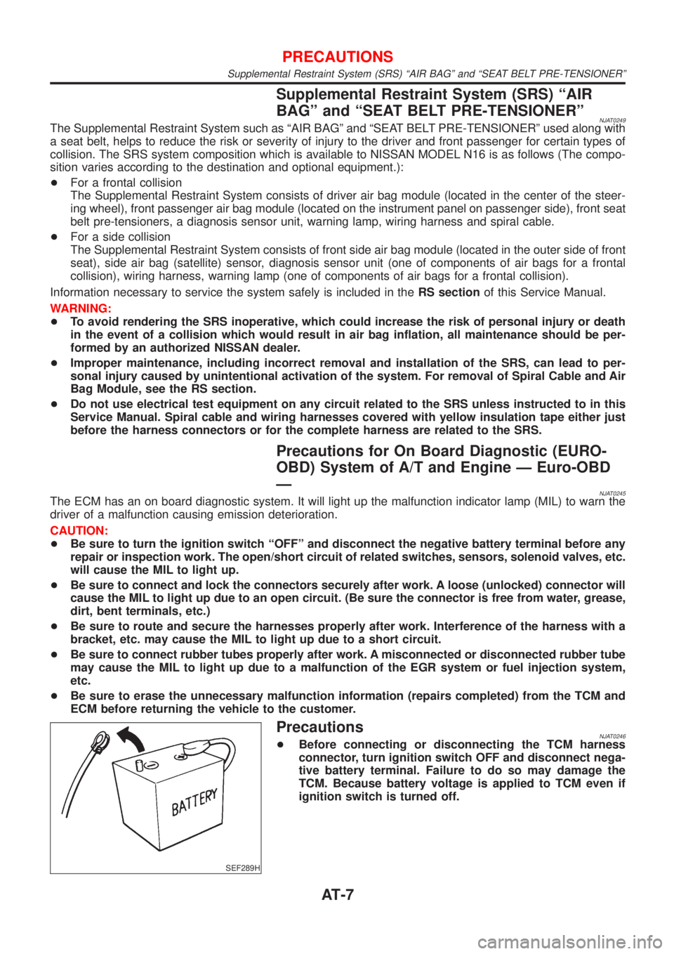
PrecautionsNJAT0246+Before connecting or disconnecting the TCM harness
connector, turn ignition switch OFF and disconnect nega-
tive battery terminal. Failure to do so may damage the
TCM. Because battery voltage is applied to TCM even if
ignition switch is turned off.
PRECAUTIONS
Supplemental Restraint System (SRS) ªAIR BAGº and ªSEAT BELT PRE-TENSIONERº
AT-7
Page 1195 of 2493
parts. Apply petroleum jelly to protect O-rings and seals, or
hold bearings and washers in place during assembly. Do not
use grease.
+Extreme care should be taken to avoid damage to O-rings,
seals and gaskets when assembling.
+After overhaul, refill the transaxle with new ATF.
+When the A/T drain plug is removed, only some of the fluid is
drained. Old A/T fluid will remain in torque converter and ATF
cooling system.
Always follow the procedures under ªChanging A/T Fluidº in the
AT section when changing A/T fluid. Refer to ªChanging A/T
Fluidº, AT-15.
Service Notice or PrecautionsNJAT0247FAIL-SAFENJAT0247S01The TCM has an electronic Fail-Safe (limp home mode). This allows the vehicle to be driven even if a major
electrical input/output device circuit is damaged.
Under Fail-Safe, the vehicle always runs in third gear, even with a shift lever position of ª1º, ª2º or ªDº. The
customer may complain of sluggish or poor acceleration.
When the ignition key is turned ªONº following Fail-Safe operation, O/D OFF indicator lamp blinks for about
8 seconds. (For EXCEPT FOR EURO-OBD; ªSELF-DIAGNOSTIC PROCEDURE (WITHOUT CONSULT-II)º,
refer to AT-42 and for EURO-OBD; ªTCM SELF-DIAGNOSTIC PROCEDURE (No Tools)º, refer to AT-61.)
Fail-Safe may occur without electrical circuit damage if the vehicle is driven under extreme conditions (such
as excessive wheel spin followed by sudden braking). To recover normal shift pattern, turn the ignition key
ªOFFº for 5 seconds, then ªONº.
The blinking of the O/D OFF indicator lamp for about 8 seconds will appear only once and be cleared. The
customer may resume normal driving conditions.
Always follow the ªWORK FLOWº [Refer to AT-71 (Except for Euro-OBD), AT-76 (EURO-OBD).]
The SELF-DIAGNOSIS results will be as follows:
The first SELF-DIAGNOSIS will indicate damage to the vehicle speed sensor or the revolution sensor.
During the next SELF-DIAGNOSIS, performed after checking the sensor, no damages will be indicated.
TORQUE CONVERTER SERVICENJAT0247S02The torque converter should be replaced under any of the following conditions:
+External leaks in the hub weld area.
+Converter hub is scored or damaged.
+Converter pilot is broken, damaged or fits poorly into crankshaft.
+Steel particles are found after flushing the cooler and cooler lines.
+Pump is damaged or steel particles are found in the converter.
+Vehicle has TCC shudder and/or no TCC apply. Replace only after all hydraulic and electrical diagnoses
have been made. (Converter clutch material may be glazed.)
+Converter is contaminated with engine coolant containing antifreeze.
+Internal failure of stator roller clutch.
+Heavy clutch debris due to overheating (blue converter).
+Steel particles or clutch lining material found in fluid filter or on magnet when no internal parts in unit are
worn or damaged Ð indicates that lining material came from converter.
The torque converter should not be replaced if:
PRECAUTIONS
Precautions (Cont'd)
AT-9