Air condition NISSAN ALMERA N16 2001 Electronic Repair Manual
[x] Cancel search | Manufacturer: NISSAN, Model Year: 2001, Model line: ALMERA N16, Model: NISSAN ALMERA N16 2001Pages: 2493, PDF Size: 66.97 MB
Page 2053 of 2493
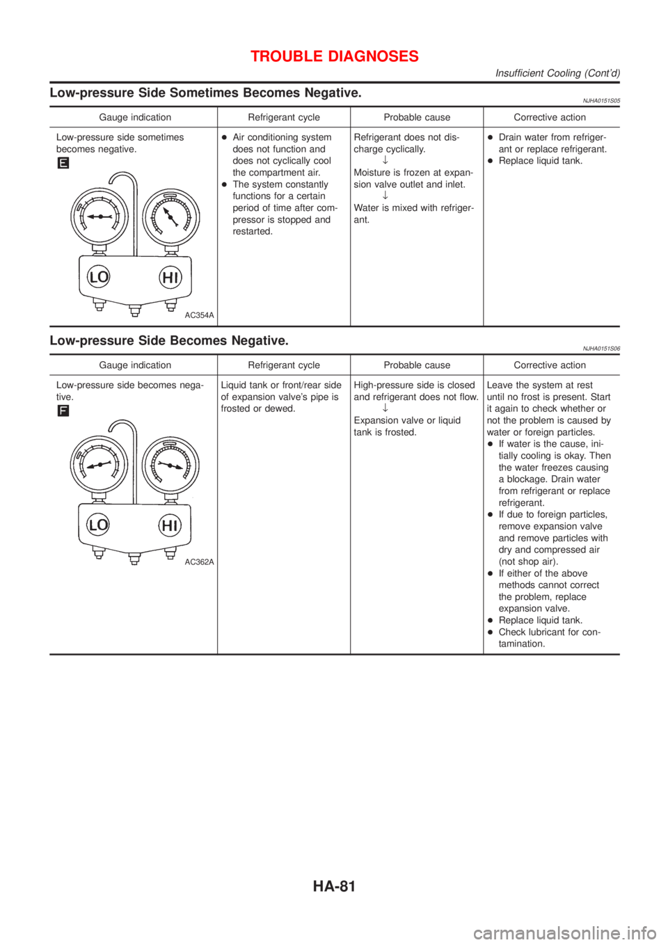
Low-pressure Side Sometimes Becomes Negative.NJHA0151S05
Gauge indication Refrigerant cycle Probable cause Corrective action
Low-pressure side sometimes
becomes negative.
AC354A
+Air conditioning system
does not function and
does not cyclically cool
the compartment air.
+The system constantly
functions for a certain
period of time after com-
pressor is stopped and
restarted.Refrigerant does not dis-
charge cyclically.
¯
Moisture is frozen at expan-
sion valve outlet and inlet.
¯
Water is mixed with refriger-
ant.+Drain water from refriger-
ant or replace refrigerant.
+Replace liquid tank.
Low-pressure Side Becomes Negative.NJHA0151S06
Gauge indication Refrigerant cycle Probable cause Corrective action
Low-pressure side becomes nega-
tive.
AC362A
Liquid tank or front/rear side
of expansion valve's pipe is
frosted or dewed.High-pressure side is closed
and refrigerant does not flow.
¯
Expansion valve or liquid
tank is frosted.Leave the system at rest
until no frost is present. Start
it again to check whether or
not the problem is caused by
water or foreign particles.
+If water is the cause, ini-
tially cooling is okay. Then
the water freezes causing
a blockage. Drain water
from refrigerant or replace
refrigerant.
+If due to foreign particles,
remove expansion valve
and remove particles with
dry and compressed air
(not shop air).
+If either of the above
methods cannot correct
the problem, replace
expansion valve.
+Replace liquid tank.
+Check lubricant for con-
tamination.
TROUBLE DIAGNOSES
Insufficient Cooling (Cont'd)
HA-81
Page 2058 of 2493
Maintenance of Lubricant Quantity in
Compressor
NJHA0160The lubricant in the compressor circulates through the system with
the refrigerant. Add lubricant to compressor when replacing any
component or after a large gas leakage occurred. It is important to
maintain the specified amount.
If lubricant quantity is not maintained properly, the following mal-
functions may result:
+Lack of lubricant: May lead to a seized compressor
+Excessive lubricant: Inadequate cooling (thermal exchange
interference)
LUBRICANTNJHA0160S01Name: Nissan A/C System Oil Type R for DKV-11G compres-
sor
Part number: KLH00-PAGR0
Name: Nissan A/C System Oil Type S for CSV613 compressor
Part number: KLH00-PAGS0
CHECKING AND ADJUSTINGNJHA0160S02Adjust the lubricant quantity according to the test group shown
below.
1 LUBRICANT RETURN OPERATION
Can lubricant return operation be performed?
+A/C system works properly.
+There is no evidence of a large amount of lubricant leakage.
YesorNo
Ye s©GO TO 2.
No©GO TO 3.
2 PERFORM LUBRICANT RETURN OPERATION, PROCEEDING AS FOLLOWS
1. Start engine, and set the following conditions:
+Test condition
Engine speed: Idling to 1,200 rpm
A/C or AUTO switch: ON
Blower speed: Max. position
Temp. control: Optional [Set so that intake air temperature is 25 to 30ÉC (77 to 86ÉF).]
2. Perform lubricant return operation for about 10 minutes.
3. Stop engine.
CAUTION:
If excessive lubricant leakage is noted, do not perform the lubricant return operation.
©GO TO 3.
3 CHECK COMPRESSOR
Should the compressor be replaced?
YesorNo
Ye s©GO TO HA-88.
No©GO TO 4.
SERVICE PROCEDURE
Maintenance of Lubricant Quantity in Compressor
HA-86
Page 2095 of 2493
SEL909TA
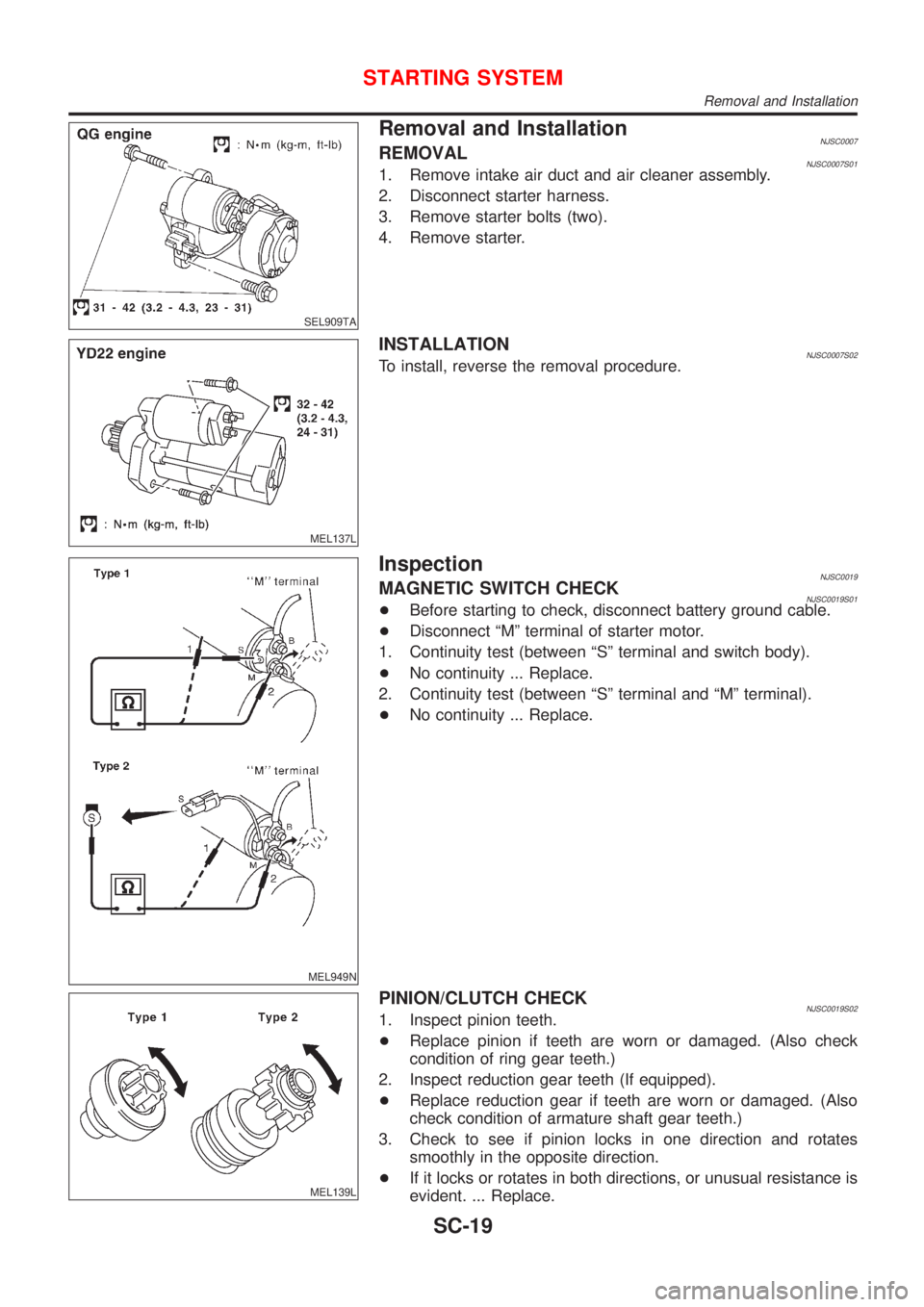
Removal and InstallationNJSC0007REMOVALNJSC0007S011. Remove intake air duct and air cleaner assembly.
2. Disconnect starter harness.
3. Remove starter bolts (two).
4. Remove starter.
MEL137L
INSTALLATIONNJSC0007S02To install, reverse the removal procedure.
MEL949N
InspectionNJSC0019MAGNETIC SWITCH CHECKNJSC0019S01+Before starting to check, disconnect battery ground cable.
+Disconnect ªMº terminal of starter motor.
1. Continuity test (between ªSº terminal and switch body).
+No continuity ... Replace.
2. Continuity test (between ªSº terminal and ªMº terminal).
+No continuity ... Replace.
MEL139L
PINION/CLUTCH CHECKNJSC0019S021. Inspect pinion teeth.
+Replace pinion if teeth are worn or damaged. (Also check
condition of ring gear teeth.)
2. Inspect reduction gear teeth (If equipped).
+Replace reduction gear if teeth are worn or damaged. (Also
check condition of armature shaft gear teeth.)
3. Check to see if pinion locks in one direction and rotates
smoothly in the opposite direction.
+If it locks or rotates in both directions, or unusual resistance is
evident. ... Replace.
STARTING SYSTEM
Removal and Installation
SC-19
Page 2114 of 2493
WARNING CHIME....................................................... 113
Component Parts and Harness Connector
Location ................................................................... 113
System Description .................................................. 113
Wiring Diagram - CHIME - ...................................... 115
Trouble Diagnoses................................................... 117
FRONT WIPER AND WASHER..................................123
System Description ..................................................123
Wiring Diagram - WIPER - ......................................125
Removal and Installation .........................................127
Washer Nozzle Adjustment .....................................128
Washer Tube Layout ...............................................128
REAR WIPER AND WASHER....................................129
Wiring Diagram - WIP/R -........................................129
Removal and Installation .........................................131
Washer Nozzle Adjustment .....................................131
Washer Tube Layout ...............................................132
HEADLAMP WASHER................................................133
Wiring Diagram - HLC - ...........................................133
Washer Tube Layout ...............................................134
HORN...........................................................................135
Wiring Diagram - HORN - .......................................135
CIGARETTE LIGHTER................................................136
Wiring Diagram - CIGAR -.......................................136
CLOCK.........................................................................137
Wiring Diagram - CLOCK -......................................137
REAR WINDOW DEFOGGER.....................................138
System Description ..................................................138
Schematic ................................................................139
Wiring Diagram - DEF - ...........................................140
Trouble Diagnoses...................................................143
Electrical Components Inspection ...........................146
Filament Check ........................................................147
Filament Repair .......................................................148
AUDIO..........................................................................149
System Description ..................................................149
Schematic ................................................................151
Wiring Diagram - AUDIO - .......................................152
Trouble Diagnoses...................................................160
Inspection.................................................................161
AUDIO ANTENNA.......................................................162
Location of Antenna .................................................162
Antenna Rod Replacement .....................................162
HEATED SEAT............................................................163
Wiring Diagram - H/SEAT - .....................................163
POWER SUNROOF.....................................................165
Wiring Diagram - SROOF - .....................................165
Trouble Diagnoses...................................................166
DOOR MIRROR...........................................................167
Wiring Diagram - MIRROR - ...................................167
POWER WINDOW.......................................................169
System Description ..................................................169Schematic ................................................................171
Wiring Diagram - WINDOW - ..................................172
Trouble Diagnoses...................................................176
POWER DOOR LOCK.................................................177
System Description ..................................................177
Schematic ................................................................178
Wiring Diagram - D/LOCK -.....................................180
Trouble Diagnoses...................................................187
POWER DOOR LOCK - SUPER LOCK -...................196
System Description ..................................................196
Schematic ................................................................198
Wiring Diagram - S/LOCK - .....................................200
Trouble Diagnoses...................................................207
MULTI-REMOTE CONTROL SYSTEM.......................220
System Description ..................................................220
Wiring Diagram - MULTI - .......................................221
Trouble Diagnoses...................................................223
ID Code Entry Procedure ........................................227
Remote Controller Battery Replacement.................228
TIME CONTROL UNIT................................................229
Description ...............................................................229
Trouble Diagnoses...................................................230
Schematic ................................................................232
NATS (NISSAN ANTI-THEFT SYSTEM).....................234
Component Parts and Harness Connetor
Location ...................................................................234
System Description ..................................................234
System Composition ................................................236
Wiring Diagram - NATS -.........................................237
CONSULT-II .............................................................238
Trouble Diagnoses...................................................241
How to Replace NATS IMMU ..................................258
NAVIGATION SYSTEM...............................................259
Precautions ..............................................................259
Component Parts Location ......................................260
System Description ..................................................261
Schematic ................................................................269
Wiring Diagram - NAVI - ..........................................270
Self-diagnosis Mode ................................................278
Confirmation/Adjustment Mode ...............................281
Control Panel Mode .................................................293
Guide Volume Setting ..............................................300
Anti-theft System .....................................................301
CONSULT-II .............................................................302
Trouble Diagnoses...................................................303
This Condition Is Not Abnormal...............................309
Program Loading .....................................................318
ELECTRICAL UNITS LOCATION...............................319
Engine Compartment ...............................................319
Passenger Compartment/LHD Models ....................320
Passenger Compartment/RHD Models ...................322
CONTENTS(Cont'd)
EL-2
Page 2272 of 2493
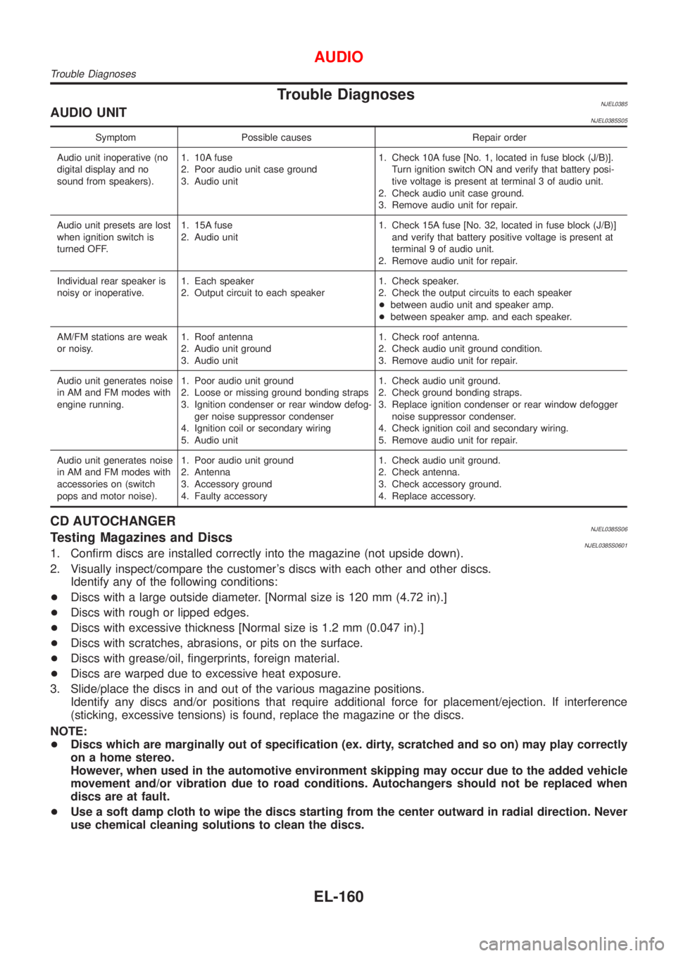
Trouble DiagnosesNJEL0385AUDIO UNITNJEL0385S05
Symptom Possible causes Repair order
Audio unit inoperative (no
digital display and no
sound from speakers).1. 10A fuse
2. Poor audio unit case ground
3. Audio unit1. Check 10A fuse [No. 1, located in fuse block (J/B)].
Turn ignition switch ON and verify that battery posi-
tive voltage is present at terminal 3 of audio unit.
2. Check audio unit case ground.
3. Remove audio unit for repair.
Audio unit presets are lost
when ignition switch is
turned OFF.1. 15A fuse
2. Audio unit1. Check 15A fuse [No. 32, located in fuse block (J/B)]
and verify that battery positive voltage is present at
terminal 9 of audio unit.
2. Remove audio unit for repair.
Individual rear speaker is
noisy or inoperative.1. Each speaker
2. Output circuit to each speaker1. Check speaker.
2. Check the output circuits to each speaker
+between audio unit and speaker amp.
+between speaker amp. and each speaker.
AM/FM stations are weak
or noisy.1. Roof antenna
2. Audio unit ground
3. Audio unit1. Check roof antenna.
2. Check audio unit ground condition.
3. Remove audio unit for repair.
Audio unit generates noise
in AM and FM modes with
engine running.1. Poor audio unit ground
2. Loose or missing ground bonding straps
3. Ignition condenser or rear window defog-
ger noise suppressor condenser
4. Ignition coil or secondary wiring
5. Audio unit1. Check audio unit ground.
2. Check ground bonding straps.
3. Replace ignition condenser or rear window defogger
noise suppressor condenser.
4. Check ignition coil and secondary wiring.
5. Remove audio unit for repair.
Audio unit generates noise
in AM and FM modes with
accessories on (switch
pops and motor noise).1. Poor audio unit ground
2. Antenna
3. Accessory ground
4. Faulty accessory1. Check audio unit ground.
2. Check antenna.
3. Check accessory ground.
4. Replace accessory.
CD AUTOCHANGERNJEL0385S06Testing Magazines and DiscsNJEL0385S06011. Confirm discs are installed correctly into the magazine (not upside down).
2. Visually inspect/compare the customer's discs with each other and other discs.
Identify any of the following conditions:
+Discs with a large outside diameter. [Normal size is 120 mm (4.72 in).]
+Discs with rough or lipped edges.
+Discs with excessive thickness [Normal size is 1.2 mm (0.047 in).]
+Discs with scratches, abrasions, or pits on the surface.
+Discs with grease/oil, fingerprints, foreign material.
+Discs are warped due to excessive heat exposure.
3. Slide/place the discs in and out of the various magazine positions.
Identify any discs and/or positions that require additional force for placement/ejection. If interference
(sticking, excessive tensions) is found, replace the magazine or the discs.
NOTE:
+Discs which are marginally out of specification (ex. dirty, scratched and so on) may play correctly
on a home stereo.
However, when used in the automotive environment skipping may occur due to the added vehicle
movement and/or vibration due to road conditions. Autochangers should not be replaced when
discs are at fault.
+Use a soft damp cloth to wipe the discs starting from the center outward in radial direction. Never
use chemical cleaning solutions to clean the discs.
AUDIO
Trouble Diagnoses
EL-160
Page 2371 of 2493
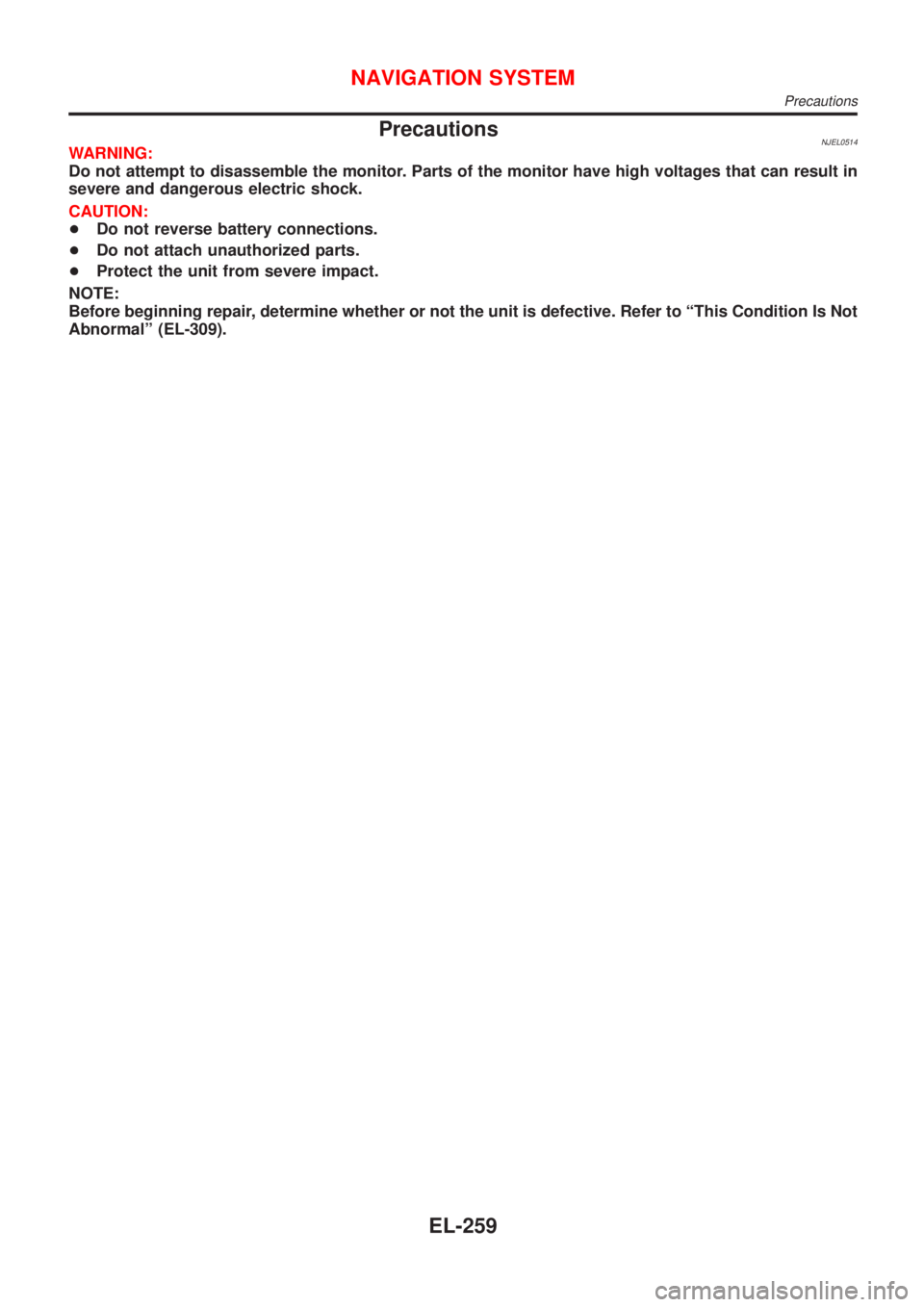
PrecautionsNJEL0514WARNING:
Do not attempt to disassemble the monitor. Parts of the monitor have high voltages that can result in
severe and dangerous electric shock.
CAUTION:
+Do not reverse battery connections.
+Do not attach unauthorized parts.
+Protect the unit from severe impact.
NOTE:
Before beginning repair, determine whether or not the unit is defective. Refer to ªThis Condition Is Not
Abnormalº (EL-309).
NAVIGATION SYSTEM
Precautions
EL-259
Page 2421 of 2493
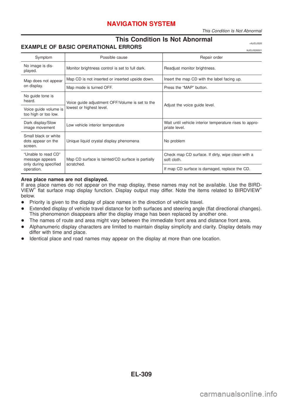
This Condition Is Not Abnormal=NJEL0526EXAMPLE OF BASIC OPERATIONAL ERRORSNJEL0526S01
Symptom Possible cause Repair order
No image is dis-
played.Monitor brightness control is set to full dark. Readjust monitor brightness.
Map does not appear
on display.Map CD is not inserted or inserted upside down. Insert the map CD with the label facing up.
Map mode is turned OFF. Press the ªMAPº button.
No guide tone is
heard.
Voice guide adjustment OFF/Volume is set to the
lowest or highest level.Adjust the voice guide level.
Voice guide volume is
too high or too low.
Dark display/Slow
image movementLow vehicle interior temperatureWait until vehicle interior temperature rises to appro-
priate level.
Small black or white
dots appear on the
screen.Unique liquid crystal display phenomena No problem
ªUnable to read CDº
message appears
only during specified
operation.Map CD surface is tainted/CD surface is partially
scratched.Check map CD surface. If dirty, wipe clean with a
soft cloth.
If map CD surface is damaged, replace the CD.
Area place names are not displayed.
If area place names do not appear on the map display, these names may not be available. Use the BIRD-
VIEW
Tflat surface map display function. Display output may differ. Note the items related to BIRDVIEWT
below.
+Priority is given to the display of place names in the direction of vehicle travel.
+Extended display of vehicle travel distance for both surfaces and steering angle (flat directional changes).
This phenomenon disappears after the display image has been replaced by another one.
+The names of route and area might vary between the immediate front area and distance front area.
+Alphanumeric display characters are limited to maintain display simplicity and clarity. Display details may
differ with time and place.
+Identical place and road names may appear on the display at more than one location.
NAVIGATION SYSTEM
This Condition Is Not Abnormal
EL-309
Page 2428 of 2493
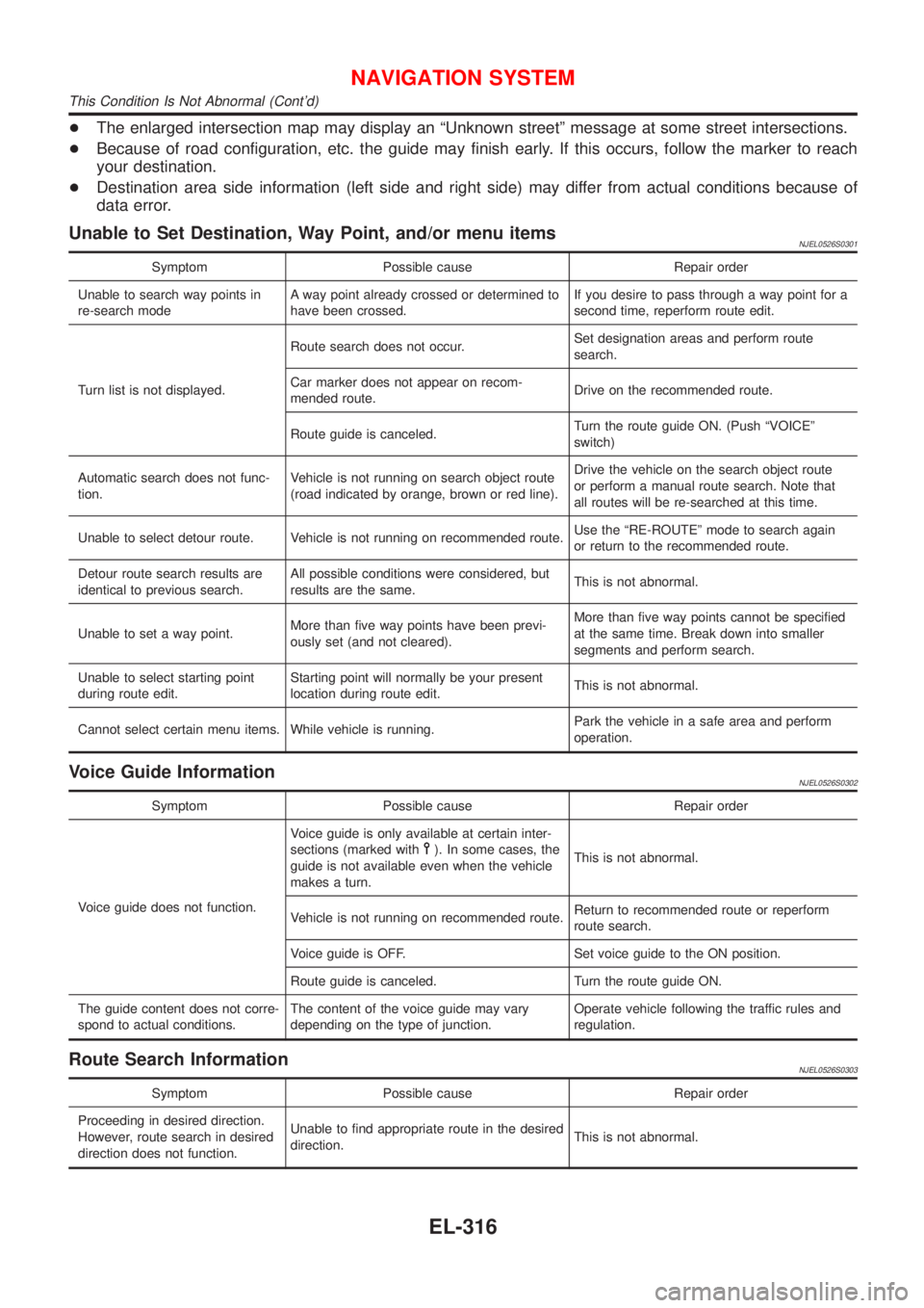
+The enlarged intersection map may display an ªUnknown streetº message at some street intersections.
+Because of road configuration, etc. the guide may finish early. If this occurs, follow the marker to reach
your destination.
+Destination area side information (left side and right side) may differ from actual conditions because of
data error.
Unable to Set Destination, Way Point, and/or menu itemsNJEL0526S0301
Symptom Possible cause Repair order
Unable to search way points in
re-search modeA way point already crossed or determined to
have been crossed.If you desire to pass through a way point for a
second time, reperform route edit.
Turn list is not displayed.Route search does not occur.Set designation areas and perform route
search.
Car marker does not appear on recom-
mended route.Drive on the recommended route.
Route guide is canceled.Turn the route guide ON. (Push ªVOICEº
switch)
Automatic search does not func-
tion.Vehicle is not running on search object route
(road indicated by orange, brown or red line).Drive the vehicle on the search object route
or perform a manual route search. Note that
all routes will be re-searched at this time.
Unable to select detour route. Vehicle is not running on recommended route.Use the ªRE-ROUTEº mode to search again
or return to the recommended route.
Detour route search results are
identical to previous search.All possible conditions were considered, but
results are the same.This is not abnormal.
Unable to set a way point.More than five way points have been previ-
ously set (and not cleared).More than five way points cannot be specified
at the same time. Break down into smaller
segments and perform search.
Unable to select starting point
during route edit.Starting point will normally be your present
location during route edit.This is not abnormal.
Cannot select certain menu items. While vehicle is running.Park the vehicle in a safe area and perform
operation.
Voice Guide InformationNJEL0526S0302
Symptom Possible cause Repair order
Voice guide does not function.Voice guide is only available at certain inter-
sections (marked with
). In some cases, the
guide is not available even when the vehicle
makes a turn.This is not abnormal.
Vehicle is not running on recommended route.Return to recommended route or reperform
route search.
Voice guide is OFF. Set voice guide to the ON position.
Route guide is canceled. Turn the route guide ON.
The guide content does not corre-
spond to actual conditions.The content of the voice guide may vary
depending on the type of junction.Operate vehicle following the traffic rules and
regulation.
Route Search InformationNJEL0526S0303
Symptom Possible cause Repair order
Proceeding in desired direction.
However, route search in desired
direction does not function.Unable to find appropriate route in the desired
direction.This is not abnormal.
NAVIGATION SYSTEM
This Condition Is Not Abnormal (Cont'd)
EL-316
Page 2429 of 2493
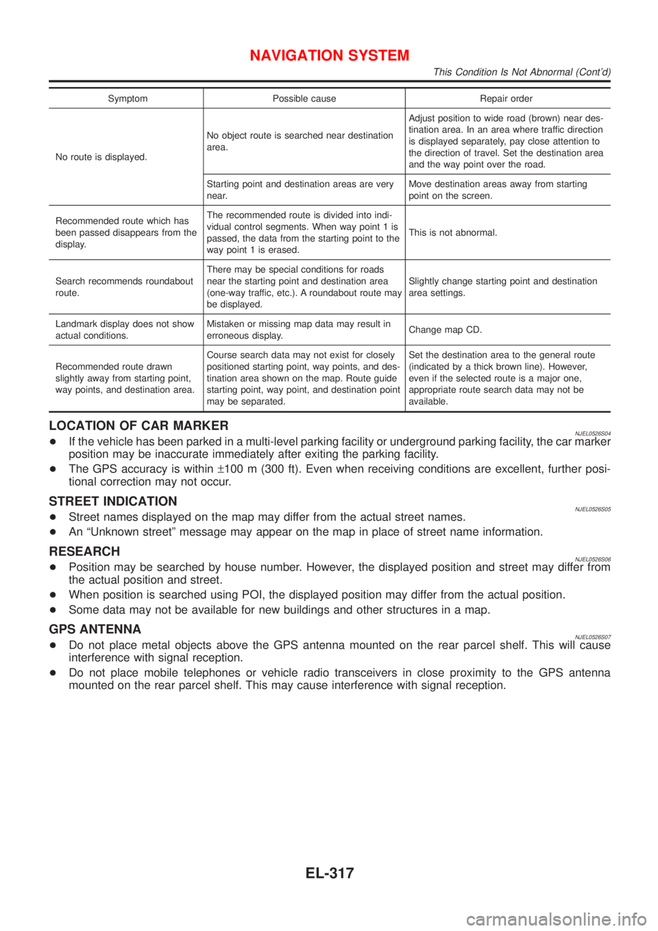
Symptom Possible cause Repair order
No route is displayed.No object route is searched near destination
area.Adjust position to wide road (brown) near des-
tination area. In an area where traffic direction
is displayed separately, pay close attention to
the direction of travel. Set the destination area
and the way point over the road.
Starting point and destination areas are very
near.Move destination areas away from starting
point on the screen.
Recommended route which has
been passed disappears from the
display.The recommended route is divided into indi-
vidual control segments. When way point 1 is
passed, the data from the starting point to the
way point 1 is erased.This is not abnormal.
Search recommends roundabout
route.There may be special conditions for roads
near the starting point and destination area
(one-way traffic, etc.). A roundabout route may
be displayed.Slightly change starting point and destination
area settings.
Landmark display does not show
actual conditions.Mistaken or missing map data may result in
erroneous display.Change map CD.
Recommended route drawn
slightly away from starting point,
way points, and destination area.Course search data may not exist for closely
positioned starting point, way points, and des-
tination area shown on the map. Route guide
starting point, way point, and destination point
may be separated.Set the destination area to the general route
(indicated by a thick brown line). However,
even if the selected route is a major one,
appropriate route search data may not be
available.
LOCATION OF CAR MARKERNJEL0526S04+If the vehicle has been parked in a multi-level parking facility or underground parking facility, the car marker
position may be inaccurate immediately after exiting the parking facility.
+The GPS accuracy is within±100 m (300 ft). Even when receiving conditions are excellent, further posi-
tional correction may not occur.
STREET INDICATIONNJEL0526S05+Street names displayed on the map may differ from the actual street names.
+An ªUnknown streetº message may appear on the map in place of street name information.
RESEARCHNJEL0526S06+Position may be searched by house number. However, the displayed position and street may differ from
the actual position and street.
+When position is searched using POI, the displayed position may differ from the actual position.
+Some data may not be available for new buildings and other structures in a map.
GPS ANTENNANJEL0526S07+Do not place metal objects above the GPS antenna mounted on the rear parcel shelf. This will cause
interference with signal reception.
+Do not place mobile telephones or vehicle radio transceivers in close proximity to the GPS antenna
mounted on the rear parcel shelf. This may cause interference with signal reception.
NAVIGATION SYSTEM
This Condition Is Not Abnormal (Cont'd)
EL-317
Page 2479 of 2493
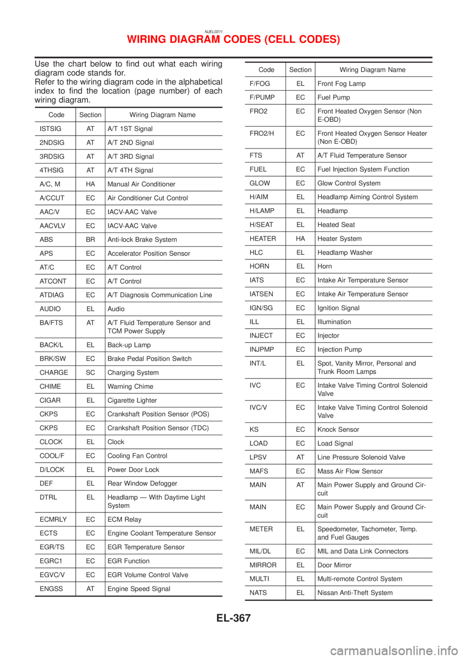
NJEL0311
Use the chart below to find out what each wiring
diagram code stands for.
Refer to the wiring diagram code in the alphabetical
index to find the location (page number) of each
wiring diagram.
Code Section Wiring Diagram Name
ISTSIG AT A/T 1ST Signal
2NDSIG AT A/T 2ND Signal
3RDSIG AT A/T 3RD Signal
4THSIG AT A/T 4TH Signal
A/C, M HA Manual Air Conditioner
A/CCUT EC Air Conditioner Cut Control
AAC/V EC IACV-AAC Valve
AACVLV EC IACV-AAC Valve
ABS BR Anti-lock Brake System
APS EC Accelerator Position Sensor
AT/C EC A/T Control
ATCONT EC A/T Control
ATDIAG EC A/T Diagnosis Communication Line
AUDIO EL Audio
BA/FTS AT A/T Fluid Temperature Sensor and
TCM Power Supply
BACK/L EL Back-up Lamp
BRK/SW EC Brake Pedal Position Switch
CHARGE SC Charging System
CHIME EL Warning Chime
CIGAR EL Cigarette Lighter
CKPS EC Crankshaft Position Sensor (POS)
CKPS EC Crankshaft Position Sensor (TDC)
CLOCK EL Clock
COOL/F EC Cooling Fan Control
D/LOCK EL Power Door Lock
DEF EL Rear Window Defogger
DTRL EL Headlamp Ð With Daytime Light
System
ECMRLY EC ECM Relay
ECTS EC Engine Coolant Temperature Sensor
EGR/TS EC EGR Temperature Sensor
EGRC1 EC EGR Function
EGVC/V EC EGR Volume Control Valve
ENGSS AT Engine Speed Signal
Code Section Wiring Diagram Name
F/FOG EL Front Fog Lamp
F/PUMP EC Fuel Pump
FRO2 EC Front Heated Oxygen Sensor (Non
E-OBD)
FRO2/H EC Front Heated Oxygen Sensor Heater
(Non E-OBD)
FTS AT A/T Fluid Temperature Sensor
FUEL EC Fuel Injection System Function
GLOW EC Glow Control System
H/AIM EL Headlamp Aiming Control System
H/LAMP EL Headlamp
H/SEAT EL Heated Seat
HEATER HA Heater System
HLC EL Headlamp Washer
HORN EL Horn
IATS EC Intake Air Temperature Sensor
IATSEN EC Intake Air Temperature Sensor
IGN/SG EC Ignition Signal
ILL EL Illumination
INJECT EC Injector
INJPMP EC Injection Pump
INT/L EL Spot, Vanity Mirror, Personal and
Trunk Room Lamps
IVC EC Intake Valve Timing Control Solenoid
Valve
IVC/V EC Intake Valve Timing Control Solenoid
Valve
KS EC Knock Sensor
LOAD EC Load Signal
LPSV AT Line Pressure Solenoid Valve
MAFS EC Mass Air Flow Sensor
MAIN AT Main Power Supply and Ground Cir-
cuit
MAIN EC Main Power Supply and Ground Cir-
cuit
METER EL Speedometer, Tachometer, Temp.
and Fuel Gauges
MIL/DL EC MIL and Data Link Connectors
MIRROR EL Door Mirror
MULTI EL Multi-remote Control System
NATS EL Nissan Anti-Theft System
WIRING DIAGRAM CODES (CELL CODES)
EL-367