NISSAN ALMERA N16 2001 Electronic Repair Manual
ALMERA N16 2001
NISSAN
NISSAN
https://www.carmanualsonline.info/img/5/57351/w960_57351-0.png
NISSAN ALMERA N16 2001 Electronic Repair Manual
Trending: wheel nut torque, engine control system, ECU, brake, tire type, transmission fluid, e p s
Page 2171 of 2493
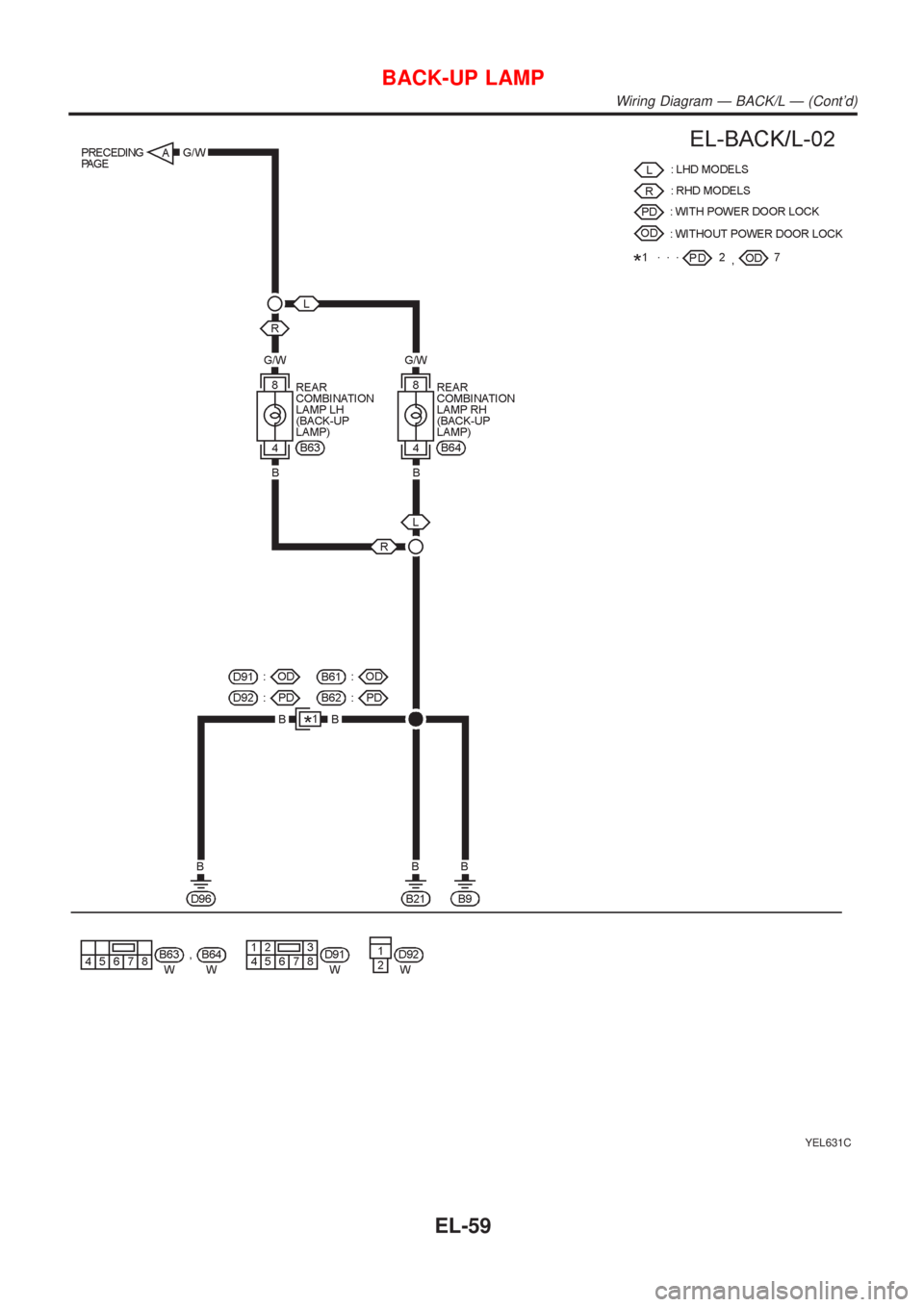
YEL631C
BACK-UP LAMP
Wiring Diagram Ð BACK/L Ð (Cont'd)
EL-59
Page 2172 of 2493
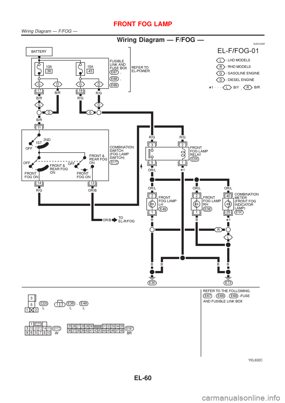
Wiring Diagram Ð F/FOG ÐNJEL0428
YEL632C
FRONT FOG LAMP
Wiring Diagram Ð F/FOG Ð
EL-60
Page 2173 of 2493
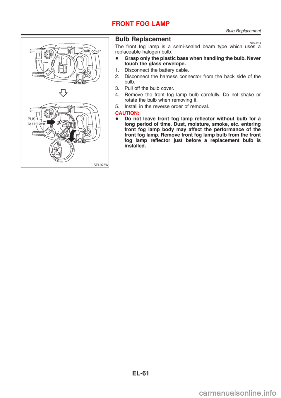
SEL975W
Bulb ReplacementNJEL0314The front fog lamp is a semi-sealed beam type which uses a
replaceable halogen bulb.
+Grasp only the plastic base when handling the bulb. Never
touch the glass envelope.
1. Disconnect the battery cable.
2. Disconnect the harness connector from the back side of the
bulb.
3. Pull off the bulb cover.
4. Remove the front fog lamp bulb carefully. Do not shake or
rotate the bulb when removing it.
5. Install in the reverse order of removal.
CAUTION:
+Do not leave front fog lamp reflector without bulb for a
long period of time. Dust, moisture, smoke, etc. entering
front fog lamp body may affect the performance of the
front fog lamp. Remove front fog lamp bulb from the front
fog lamp reflector just before a replacement bulb is
installed.
FRONT FOG LAMP
Bulb Replacement
EL-61
Page 2174 of 2493
SEL976W
SEL480X
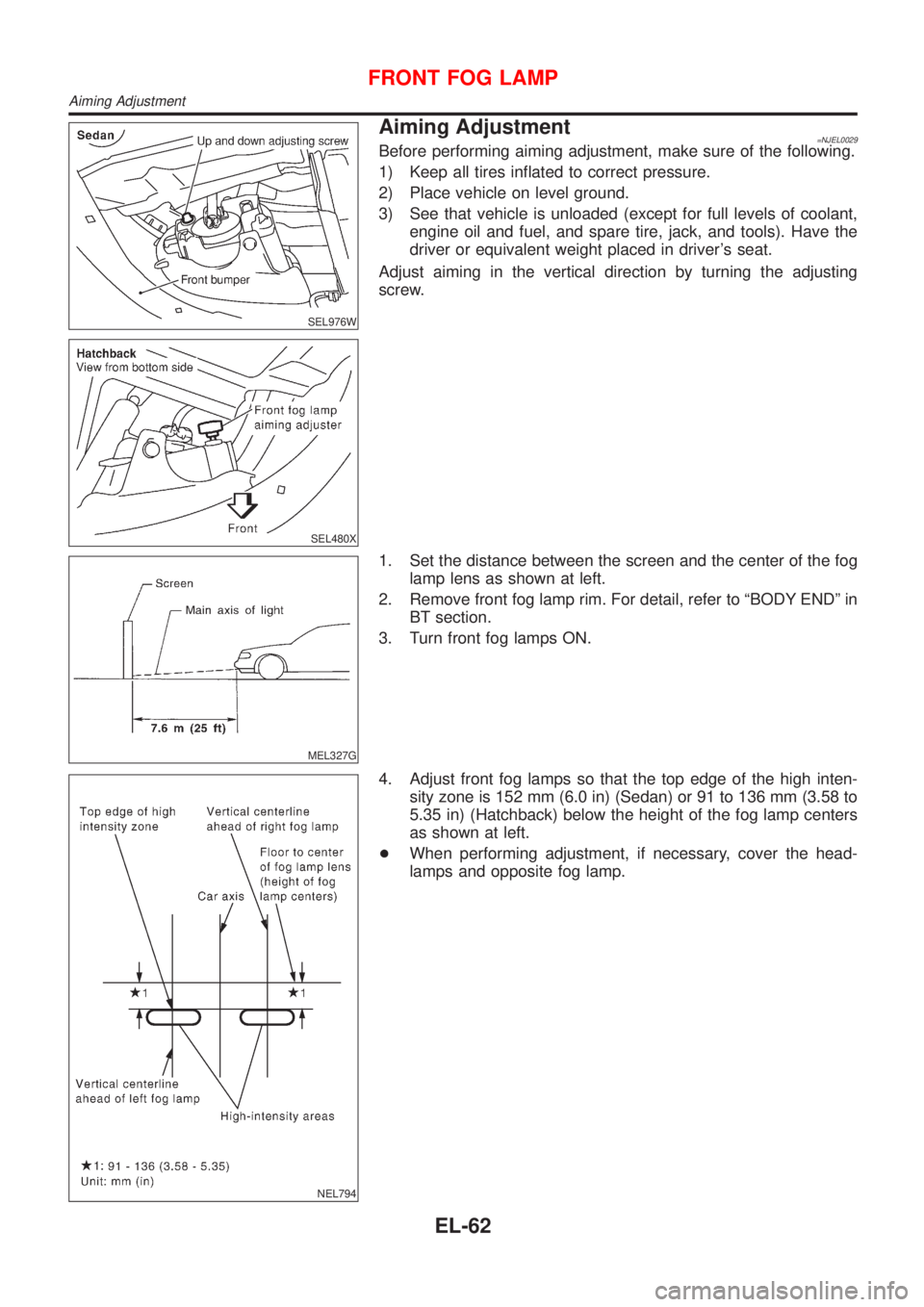
Aiming Adjustment=NJEL0029Before performing aiming adjustment, make sure of the following.
1) Keep all tires inflated to correct pressure.
2) Place vehicle on level ground.
3) See that vehicle is unloaded (except for full levels of coolant,
engine oil and fuel, and spare tire, jack, and tools). Have the
driver or equivalent weight placed in driver's seat.
Adjust aiming in the vertical direction by turning the adjusting
screw.
MEL327G
1. Set the distance between the screen and the center of the fog
lamp lens as shown at left.
2. Remove front fog lamp rim. For detail, refer to ªBODY ENDº in
BT section.
3. Turn front fog lamps ON.
NEL794
4. Adjust front fog lamps so that the top edge of the high inten-
sity zone is 152 mm (6.0 in) (Sedan) or 91 to 136 mm (3.58 to
5.35 in) (Hatchback) below the height of the fog lamp centers
as shown at left.
+When performing adjustment, if necessary, cover the head-
lamps and opposite fog lamp.
FRONT FOG LAMP
Aiming Adjustment
EL-62
Page 2175 of 2493
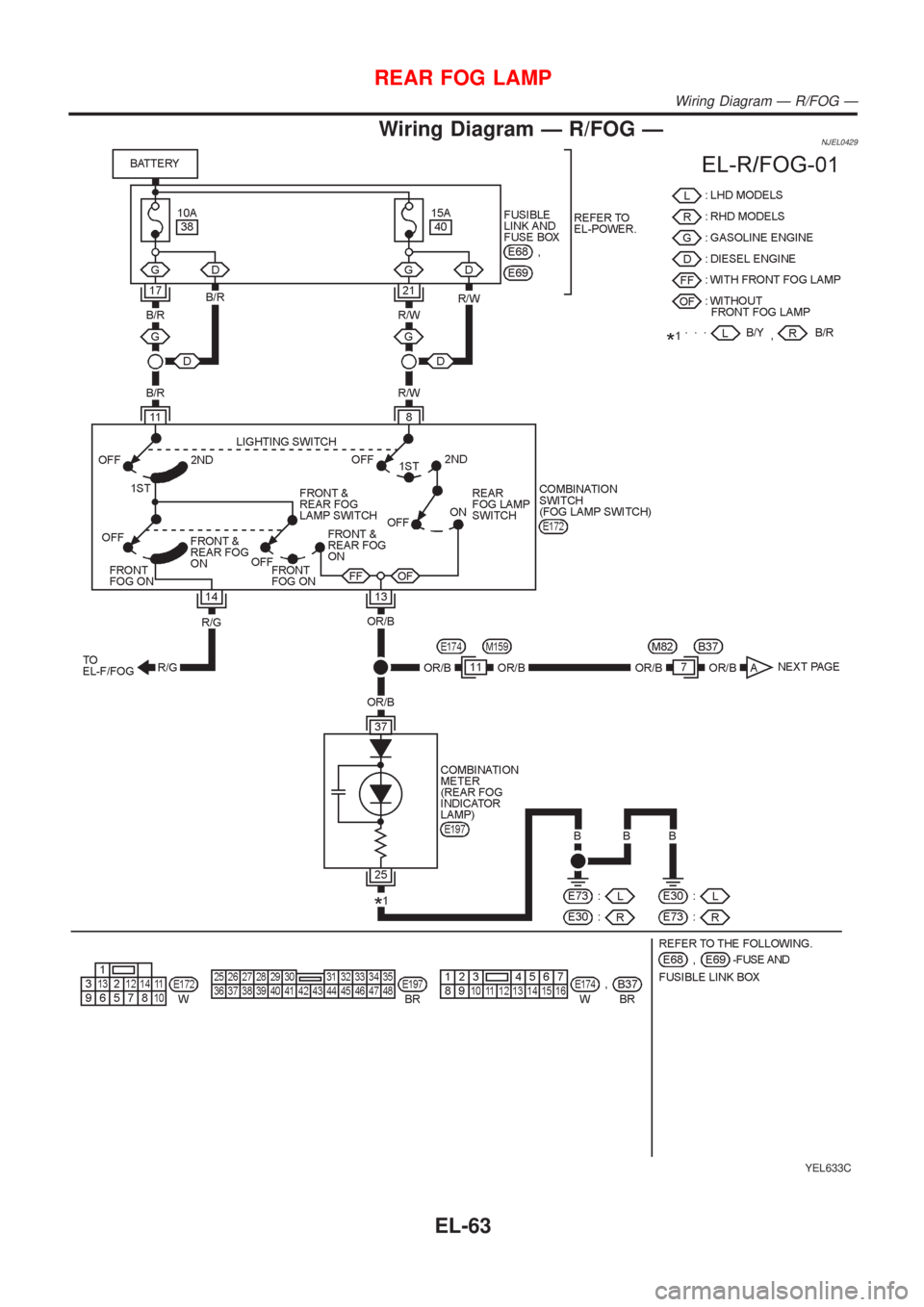
Wiring Diagram Ð R/FOG ÐNJEL0429
YEL633C
REAR FOG LAMP
Wiring Diagram Ð R/FOG Ð
EL-63
Page 2176 of 2493
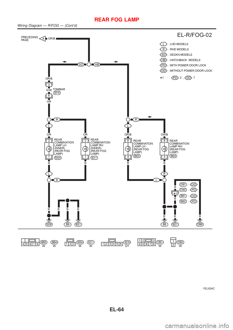
YEL634C
REAR FOG LAMP
Wiring Diagram Ð R/FOG Ð (Cont'd)
EL-64
Page 2177 of 2493
![NISSAN ALMERA N16 2001 Electronic Repair Manual System DescriptionNJEL0430TURN SIGNAL OPERATIONNJEL0430S01Power is supplied at all times
+through 15A fuse [No. 5, located in fuse block (J/B)]
+to time control unit terminal 9
With the ignition switc NISSAN ALMERA N16 2001 Electronic Repair Manual System DescriptionNJEL0430TURN SIGNAL OPERATIONNJEL0430S01Power is supplied at all times
+through 15A fuse [No. 5, located in fuse block (J/B)]
+to time control unit terminal 9
With the ignition switc](/img/5/57351/w960_57351-2176.png)
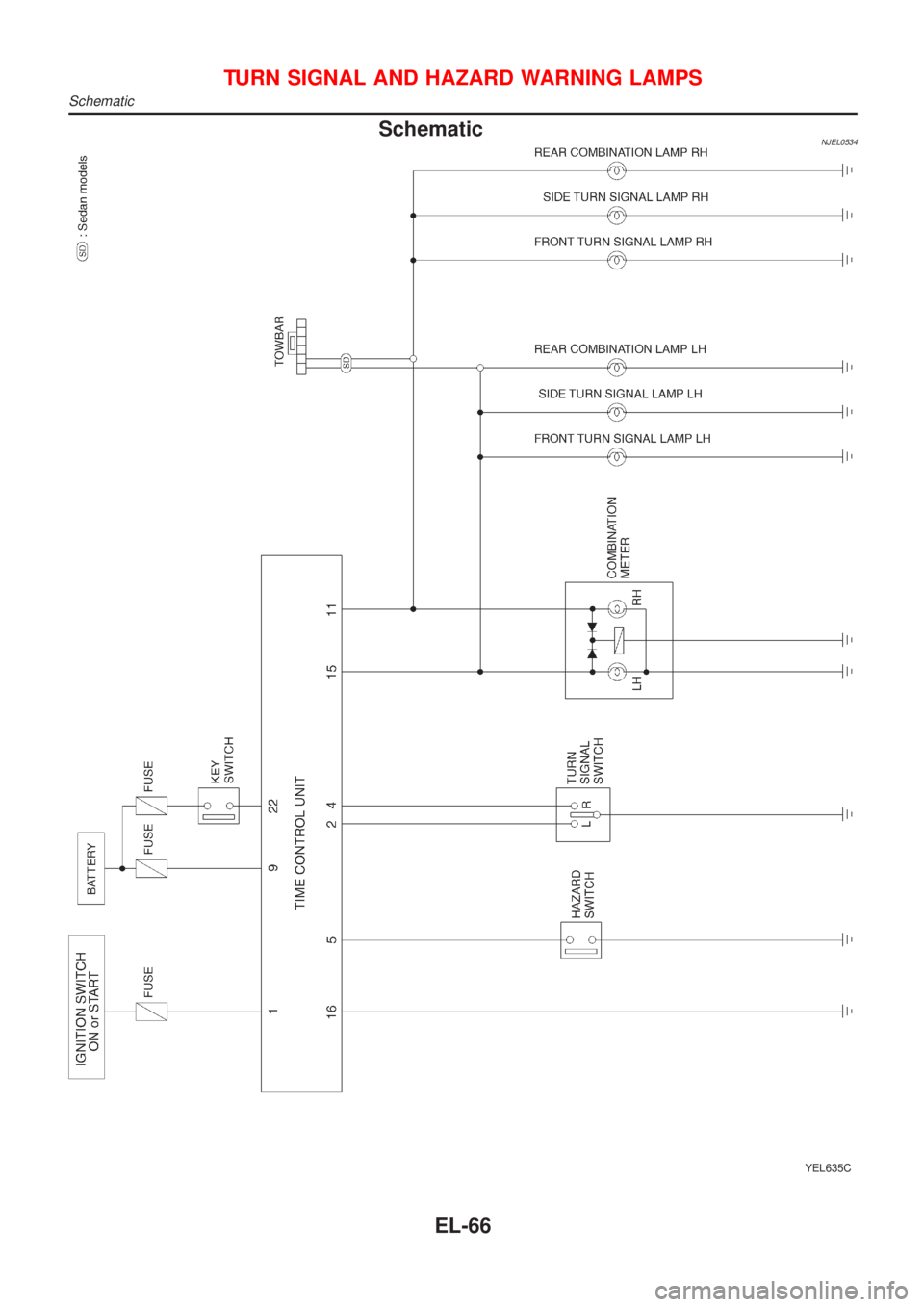
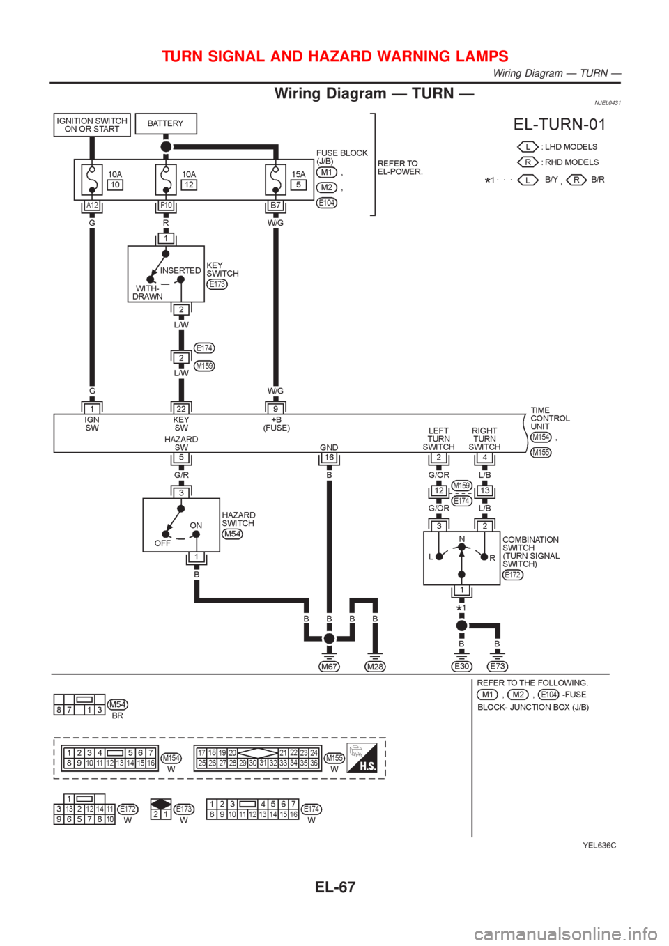
System DescriptionNJEL0430TURN SIGNAL OPERATIONNJEL0430S01Power is supplied at all times
+through 15A fuse [No. 5, located in fuse block (J/B)]
+to time control unit terminal 9
With the ignition switch in the ON or START position, power is supplied
+through 10A fuse [No. 10, located in fuse block (J/B)]
+to time control unit terminal 1
Ground is supplied to time control unit terminal 16 through body grounds M28 and M67.
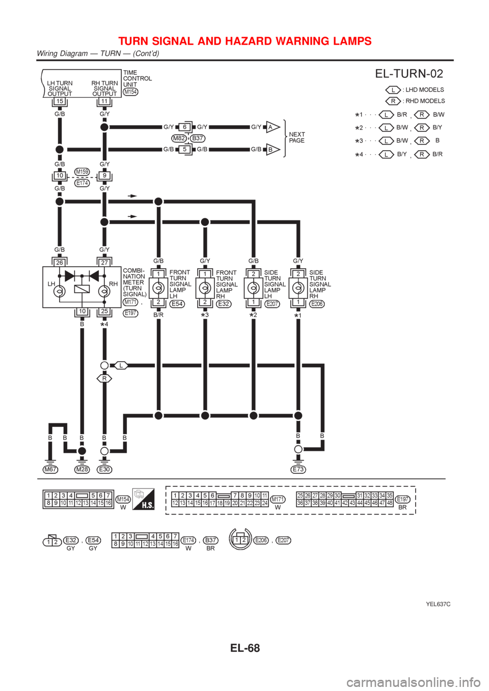
LH TurnNJEL0430S0101When the turn signal switch is moved to the L position, ground is supplied from body grounds E30 and E73
to
+time control unit terminal 2
+through turn signal switch terminal 3
With ground is supplied, time control unit controls the flashing of the LH turn signal lamps.
RH TurnNJEL0430S0102When the turn signal switch is moved to the R position, ground is supplied from body grounds E30 and E73
to
+time control unit terminal 4
+through turn signal switch terminal 2
With ground is supplied, time control unit controls the flashing of the RH turn signal lamps.
HAZARD LAMP OPERATIONNJEL0430S02Power is supplied at all times
+through 15A fuse [No. 5, located in fuse block (J/B)]
+to time control unit terminal 9
Ground is supplied to time control unit terminal 16 through body grounds M28 and M67.
With the hazard switch in the ON position, ground is supplied from body grounds M28 and M67 to
+time control unit terminals 1 and 5
+through hazard switch terminal 3
With ground is supplied, time control unit controls the flashing of the hazard warning lamps.
HAZARD REMINDER OPERATION FOR MULTI-REMOTE CONTROL SYSTEMNJEL0430S04When the doors are locked or unlocked by multi-remote controller, time control unit controls turn lamps haz-
ard reminder flashes as follows.
+Locked operation: Flash once
+Unlock operation: Flash twice
TURN SIGNAL AND HAZARD WARNING LAMPS
System Description
EL-65
Page 2178 of 2493
SchematicNJEL0534
YEL635C
TURN SIGNAL AND HAZARD WARNING LAMPS
Schematic
EL-66
Page 2179 of 2493
Wiring Diagram Ð TURN ÐNJEL0431
YEL636C
TURN SIGNAL AND HAZARD WARNING LAMPS
Wiring Diagram Ð TURN Ð
EL-67
Page 2180 of 2493
YEL637C
TURN SIGNAL AND HAZARD WARNING LAMPS
Wiring Diagram Ð TURN Ð (Cont'd)
EL-68
Trending: Idle control valve, steering wheel, Starting system, ad blue, Parking, lock, Meter wiring

![NISSAN ALMERA N16 2001 Electronic Repair Manual System DescriptionNJEL0430TURN SIGNAL OPERATIONNJEL0430S01Power is supplied at all times
+through 15A fuse [No. 5, located in fuse block (J/B)]
+to time control unit terminal 9
With the ignition switc NISSAN ALMERA N16 2001 Electronic Repair Manual System DescriptionNJEL0430TURN SIGNAL OPERATIONNJEL0430S01Power is supplied at all times
+through 15A fuse [No. 5, located in fuse block (J/B)]
+to time control unit terminal 9
With the ignition switc](/img/5/57351/w960_57351-2176.png)
