NISSAN ALMERA N16 2001 Electronic Repair Manual
ALMERA N16 2001
NISSAN
NISSAN
https://www.carmanualsonline.info/img/5/57351/w960_57351-0.png
NISSAN ALMERA N16 2001 Electronic Repair Manual
Trending: Hand break, navigation system, clock reset, rear lam, set clock, height, pairing phone
Page 2241 of 2493
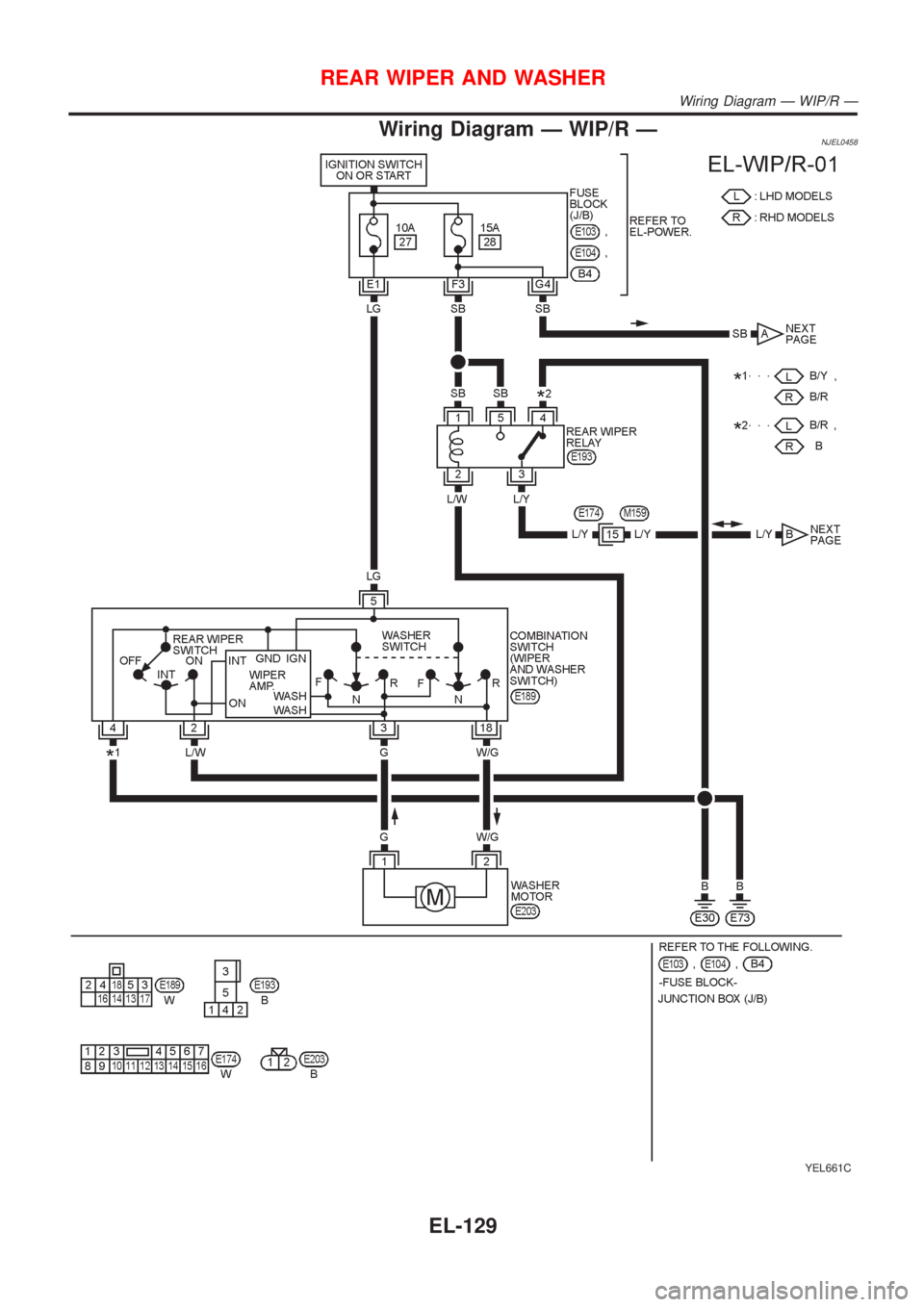
Wiring Diagram Ð WIP/R ÐNJEL0458
YEL661C
REAR WIPER AND WASHER
Wiring Diagram Ð WIP/R Ð
EL-129
Page 2242 of 2493
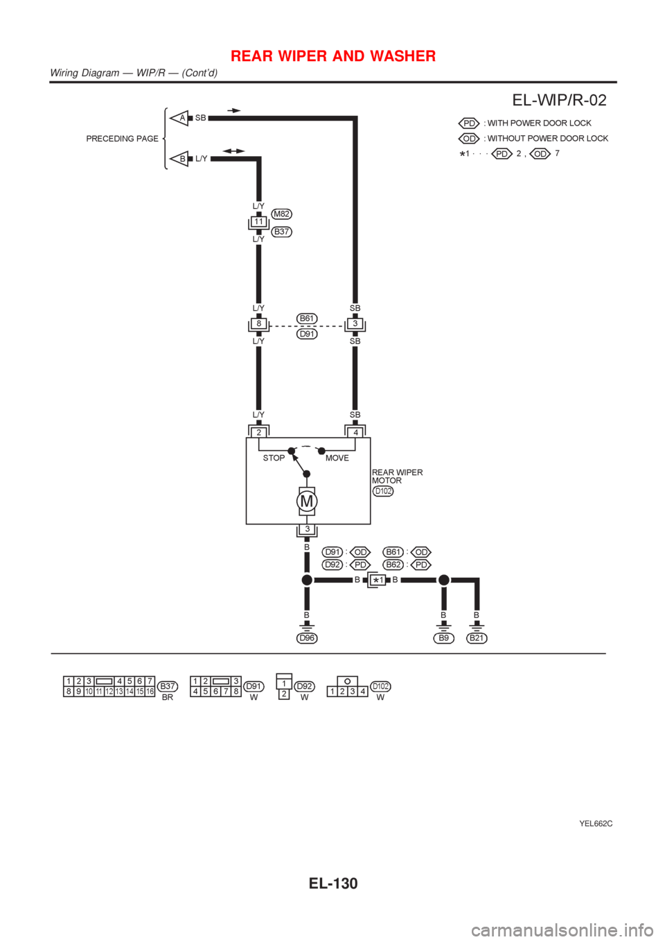
YEL662C
REAR WIPER AND WASHER
Wiring Diagram Ð WIP/R Ð (Cont'd)
EL-130
Page 2243 of 2493
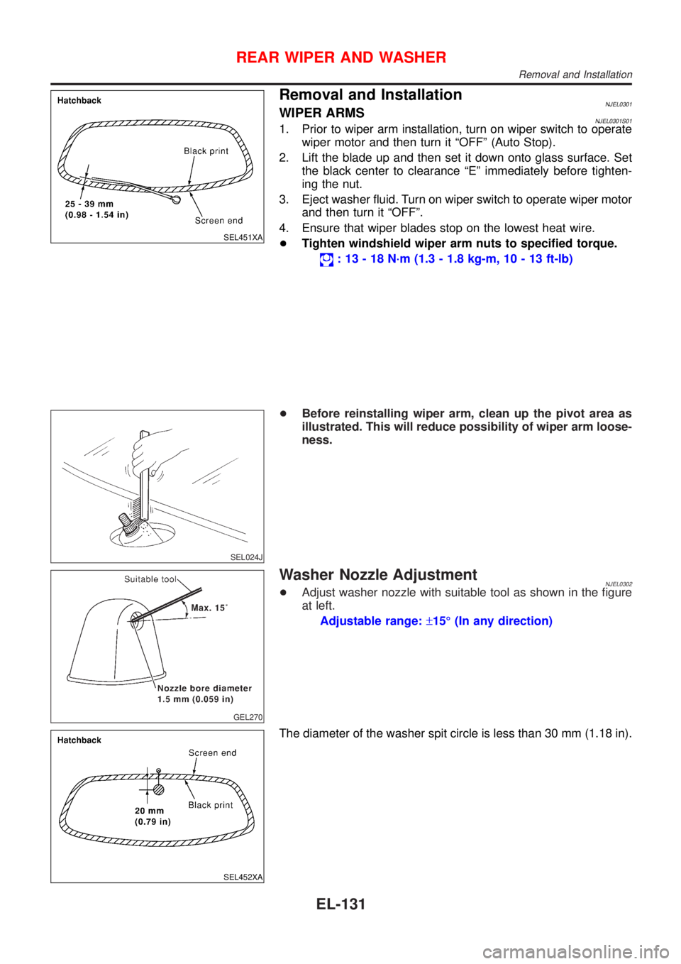
SEL451XA
Removal and InstallationNJEL0301WIPER ARMSNJEL0301S011. Prior to wiper arm installation, turn on wiper switch to operate
wiper motor and then turn it ªOFFº (Auto Stop).
2. Lift the blade up and then set it down onto glass surface. Set
the black center to clearance ªEº immediately before tighten-
ing the nut.
3. Eject washer fluid. Turn on wiper switch to operate wiper motor
and then turn it ªOFFº.
4. Ensure that wiper blades stop on the lowest heat wire.
+Tighten windshield wiper arm nuts to specified torque.
: 13 - 18 N´m (1.3 - 1.8 kg-m, 10 - 13 ft-lb)
SEL024J
+Before reinstalling wiper arm, clean up the pivot area as
illustrated. This will reduce possibility of wiper arm loose-
ness.
GEL270
Washer Nozzle AdjustmentNJEL0302+Adjust washer nozzle with suitable tool as shown in the figure
at left.
Adjustable range:±15É (In any direction)
SEL452XA
The diameter of the washer spit circle is less than 30 mm (1.18 in).
REAR WIPER AND WASHER
Removal and Installation
EL-131
Page 2244 of 2493
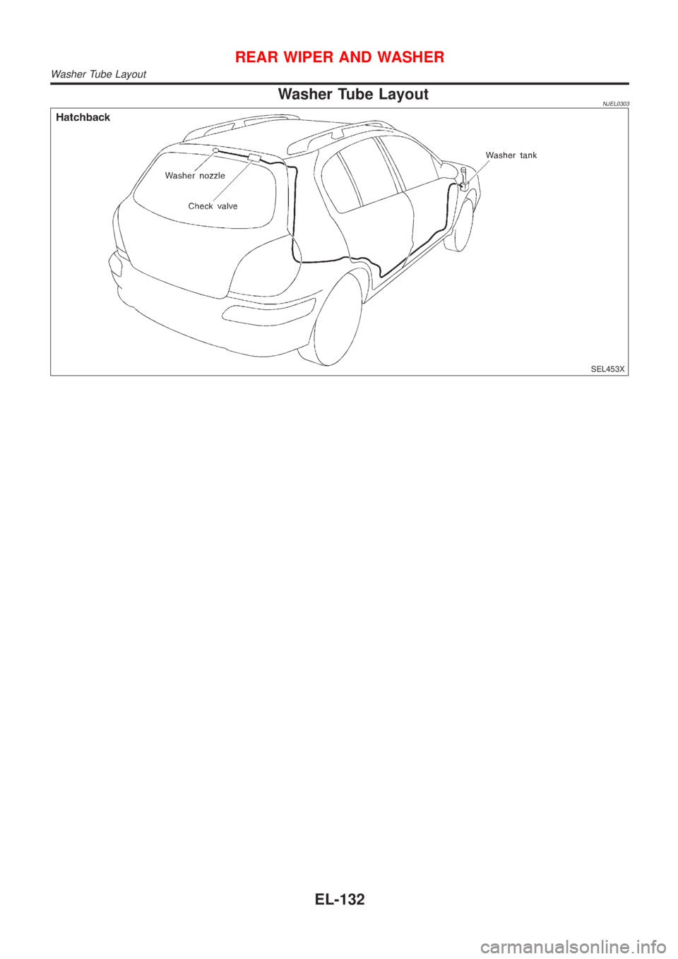
Washer Tube LayoutNJEL0303
SEL453X
REAR WIPER AND WASHER
Washer Tube Layout
EL-132
Page 2245 of 2493
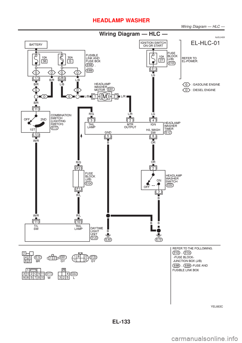
Wiring Diagram Ð HLC ÐNJEL0459
YEL663C
HEADLAMP WASHER
Wiring Diagram Ð HLC Ð
EL-133
Page 2246 of 2493
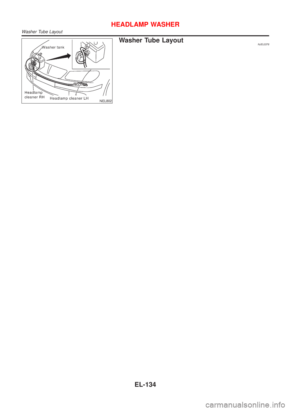
NEL802
Washer Tube LayoutNJEL0376
HEADLAMP WASHER
Washer Tube Layout
EL-134
Page 2247 of 2493
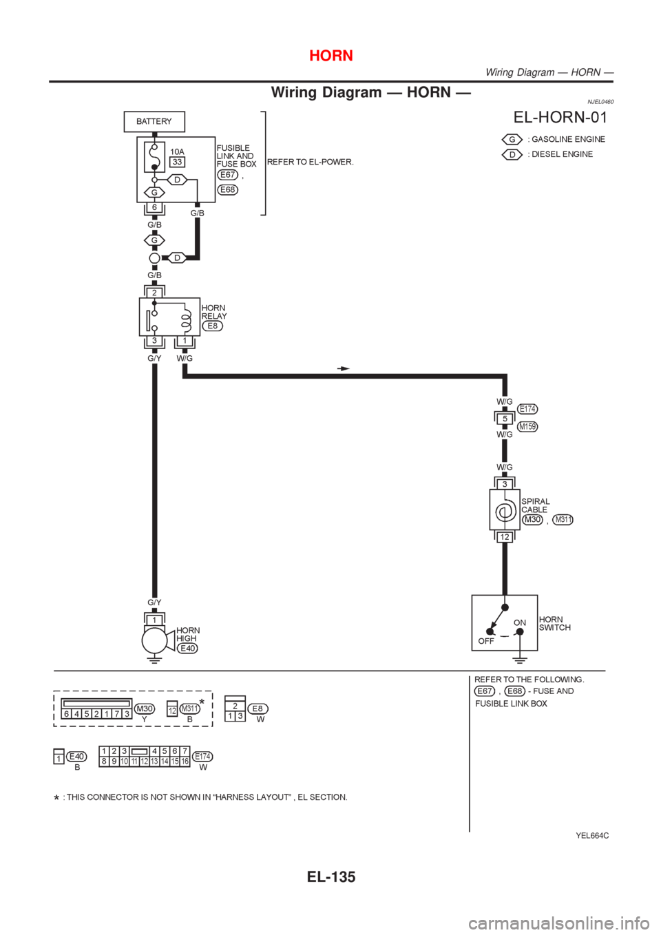
Wiring Diagram Ð HORN ÐNJEL0460
YEL664C
HORN
Wiring Diagram Ð HORN Ð
EL-135
Page 2248 of 2493
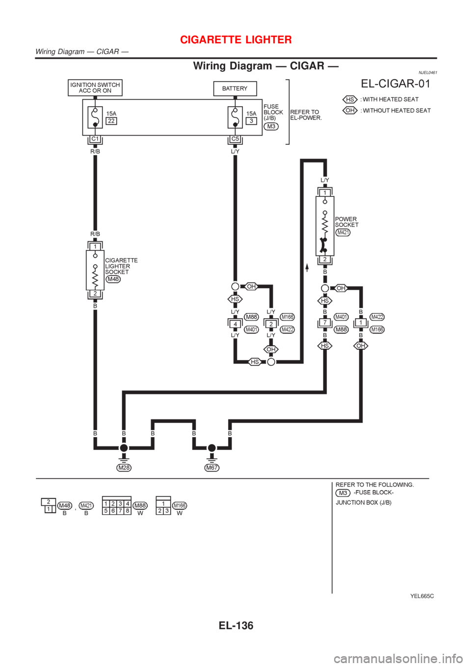
Wiring Diagram Ð CIGAR ÐNJEL0461
YEL665C
CIGARETTE LIGHTER
Wiring Diagram Ð CIGAR Ð
EL-136
Page 2249 of 2493
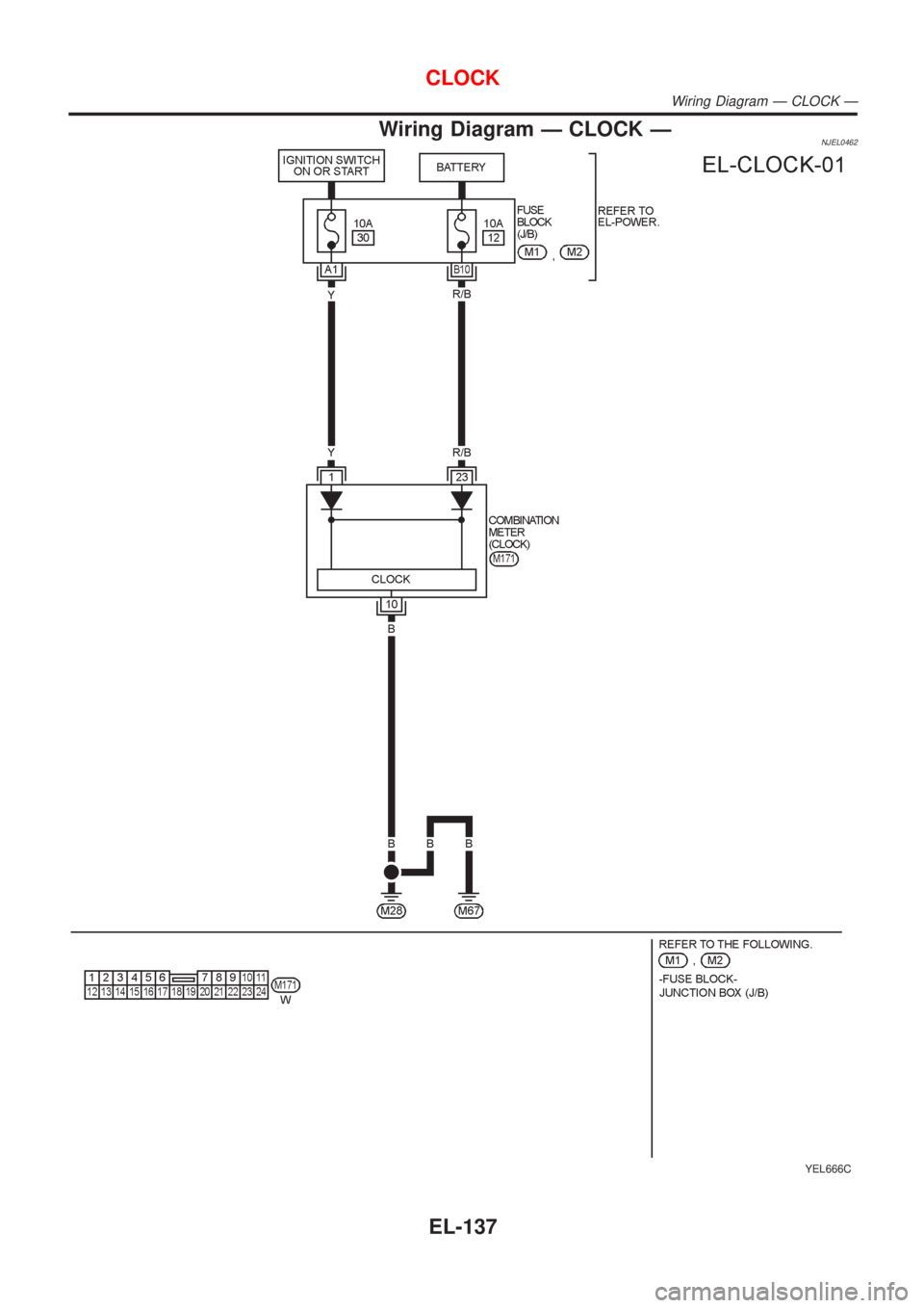
Wiring Diagram Ð CLOCK ÐNJEL0462
YEL666C
CLOCK
Wiring Diagram Ð CLOCK Ð
EL-137
Page 2250 of 2493
System Description=NJEL0463The rear window defogger system is controlled by the time control unit. The rear window defogger operates
only for approximately 15 minutes.
Power is supplied at all times
+through 20A fuse [No. 7, located in the fuse block (J/B)]
+to rear window defogger relay terminal 5 (B7 relay models) or 3 (B6 relay models)
+through 10A fuse [No. 13, located in the fuse block (J/B)]
+to rear window defogger relay terminal 6 (B6 relay models).
+through 15A fuse [No. 5, located in the fuse block (J/B)]
+to time control unit terminal 9.
With the ignition switch in the ON or START position, power is supplied
+through 10A fuse [No. 10, located in the fuse block (J/B)]
+to the rear window defogger relay terminal 1 and
+to time control unit terminal 1.
Ground is supplied to terminal 5 of the rear window defogger switch through body grounds M28 and M67.
When the rear defogger switch is turned ON, ground is supplied
+through terminal 3 of the rear defogger switch
+to time control unit terminal 3.
Terminal 13 of time control unit then supplies ground to the rear window defogger relay terminal 2.
With power and ground supplied, the rear window defogger relay is energized.
Power is supplied
+through terminals 5 and 7 of the rear window defogger relay (B6 relay models) or
+through terminal 3 of the rear window defogger relay (B7 relay models)
+to the rear window defogger and door mirror defogger.
The rear window defogger has an independent ground.
With power and ground supplied, the rear window defogger filaments heat and defog the rear window.
When the system is activated, the rear window defogger indicator illuminates in the rear window defogger
switch.
REAR WINDOW DEFOGGER
System Description
EL-138
Trending: Tail, dead battery, Power steering manual, height, warning light, Combination meter, air bleeding
