brake NISSAN ALMERA N16 2001 Electronic Owner's Manual
[x] Cancel search | Manufacturer: NISSAN, Model Year: 2001, Model line: ALMERA N16, Model: NISSAN ALMERA N16 2001Pages: 2493, PDF Size: 66.97 MB
Page 789 of 2493
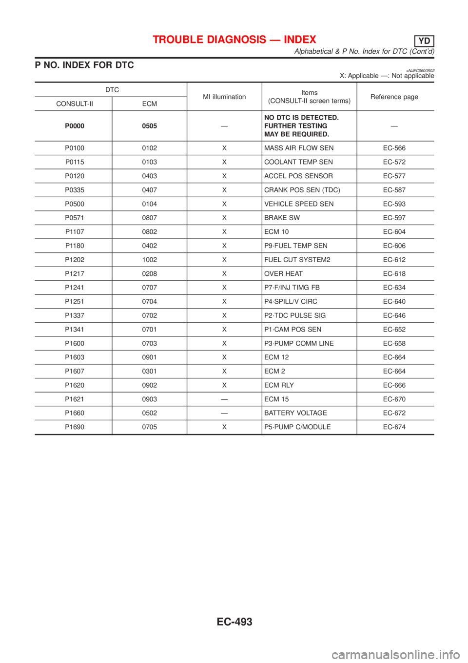
P NO. INDEX FOR DTC=NJEC0600S02X: Applicable Ð: Not applicable
DTC
MI illuminationItems
(CONSULT-II screen terms)Reference page
CONSULT-II ECM
P0000 0505ÐNO DTC IS DETECTED.
FURTHER TESTING
MAY BE REQUIRED.Ð
P0100 0102 X MASS AIR FLOW SEN EC-566
P0115 0103 X COOLANT TEMP SEN EC-572
P0120 0403 X ACCEL POS SENSOR EC-577
P0335 0407 X CRANK POS SEN (TDC) EC-587
P0500 0104 X VEHICLE SPEED SEN EC-593
P0571 0807 X BRAKE SW EC-597
P1107 0802 X ECM 10 EC-604
P1180 0402 X P9´FUEL TEMP SEN EC-606
P1202 1002 X FUEL CUT SYSTEM2 EC-612
P1217 0208 X OVER HEAT EC-618
P1241 0707 X P7´F/INJ TIMG FB EC-634
P1251 0704 X P4´SPILL/V CIRC EC-640
P1337 0702 X P2´TDC PULSE SIG EC-646
P1341 0701 X P1´CAM POS SEN EC-652
P1600 0703 X P3´PUMP COMM LINE EC-658
P1603 0901 X ECM 12 EC-664
P1607 0301 X ECM 2 EC-664
P1620 0902 X ECM RLY EC-666
P1621 0903 Ð ECM 15 EC-670
P1660 0502 Ð BATTERY VOLTAGE EC-672
P1690 0705 X P5´PUMP C/MODULE EC-674
TROUBLE DIAGNOSIS Ð INDEXYD
Alphabetical & P No. Index for DTC (Cont'd)
EC-493
Page 816 of 2493
Fuel Filter
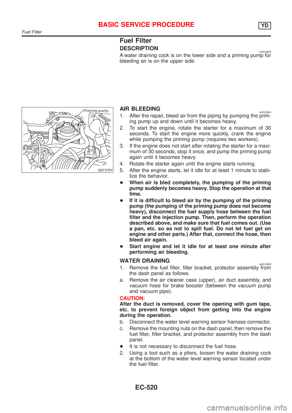
DESCRIPTIONNJEC0623A water draining cock is on the lower side and a priming pump for
bleeding air is on the upper side.
SEF375Y
AIR BLEEDINGNJEC06241. After the repair, bleed air from the piping by pumping the prim-
ing pump up and down until it becomes heavy.
2. To start the engine, rotate the starter for a maximum of 30
seconds. To start the engine more quickly, crank the engine
while pumping the priming pump (requires two workers).
3. If the engine does not start after rotating the starter for a maxi-
mum of 30 seconds, stop it once, and pump the priming pump
again until it becomes heavy.
4. Rotate the starter again until the engine starts running.
5. After the engine starts, let it idle for at least 1 minute to stabi-
lize the behavior.
+When air is bled completely, the pumping of the priming
pump suddenly becomes heavy. Stop the operation at that
time.
+If it is difficult to bleed air by the pumping of the priming
pump (the pumping of the priming pump does not become
heavy), disconnect the fuel supply hose between the fuel
filter and the injection pump. Then, perform the operation
described above, and make sure that fuel comes out. (Use
a pan, etc. so as not to spill fuel. Do not let fuel get on
engine and other parts.) After that, connect the hose, then
bleed air again.
+Start engine and let it idle for at least one minute after
performing air bleeding.
WATER DRAININGNJEC06251. Remove the fuel filter, filter bracket, protector assembly from
the dash panel as follows.
a. Remove the air cleaner case (upper), air duct assembly, and
vacuum hose for brake booster (between the vacuum pump
and vacuum pipe).
CAUTION:
After the duct is removed, cover the opening with gum tape,
etc. to prevent foreign object from getting into the engine
during the operation.
b. Disconnect the water level warning sensor harness connector.
c. Remove the mounting nuts on the dash panel, then remove the
fuel filter, filter bracket, and protector assembly from the dash
panel.
+It is not necessary to disconnect the fuel hose.
2. Using a tool such as a pliers, loosen the water draining cock
at the bottom of the water level warning sensor located under
the fuel filter.
BASIC SERVICE PROCEDUREYD
Fuel Filter
EC-520
Page 825 of 2493
![NISSAN ALMERA N16 2001 Electronic Owners Manual Monitored item
[Unit]ECM
input
signalsMain
signalsDescription Remarks
SPILL/V [ÉCA]
j+The control position of spill valve (sent
from electronic control fuel injection
pump) is displayed.
BATTERY VOLT NISSAN ALMERA N16 2001 Electronic Owners Manual Monitored item
[Unit]ECM
input
signalsMain
signalsDescription Remarks
SPILL/V [ÉCA]
j+The control position of spill valve (sent
from electronic control fuel injection
pump) is displayed.
BATTERY VOLT](/img/5/57351/w960_57351-824.png)
Monitored item
[Unit]ECM
input
signalsMain
signalsDescription Remarks
SPILL/V [ÉCA]
j+The control position of spill valve (sent
from electronic control fuel injection
pump) is displayed.
BATTERY VOLT [V]
jj+The power supply voltage of ECM is
displayed.
P/N POSI SW*1
[ON/OFF] (where
fitted)jj+Indicates [ON/OFF] condition from the
park/neutral position switch signal.
START SIGNAL
[ON/OFF]jj+Indicates [ON/OFF] condition from the
starter signal.+After starting the engine, [OFF] is dis-
played regardless of the starter signal.
BRAKE SW
[ON/OFF]jj+Indicates [ON/OFF] condition from the
stop lamp switch signal.
BRAKE SW2
[ON/OFF]jj+Indicates [ON/OFF] condition from the
brake pedal position switch signal.
IGN SW
[ON/OFF]jj+Indicates [ON/OFF] condition from igni-
tion switch signal.
MAS AIR/FL SE [V]
jj+The signal voltage of the mass air flow
sensor is displayed.+When the engine is stopped, a certain
value is indicated.
INT/A VOLUME [mg/]+The intake air volume computed from
the mass air flow sensor signal is dis-
played.
F/CUT SIGNAL
[ON/OFF]
j+The [ON/OFF] condition from decelera-
tion fuel cut signal (sent from electronic
control fuel injection pump) is displayed.
OFF´´´Fuel is cut off.
ON´´´Fuel is not cut off.
GLOW RLY
[ON/OFF]j+The glow relay control condition (deter-
mined by ECM according to the input
signal) is displayed.
COOLING FAN
[LOW/HI/OFF]
j+Indicates the control condition of the
cooling fans (determined by ECM
according to the input signal).
+LOW ... Operates at low speed.
HI ... Operates at high speed.
OFF ... Stopped.
BARO SEN [kPa]
jj+The barometric pressure (determined
by the signal voltage from the baromet-
ric pressure sensor built into the ECM)
is displayed.
EGR VOL CON/V
[step]
j+Indicates the EGR volume control value
computed by the ECM according to the
input signals.
+The opening becomes larger as the
value increases.
*1: On models not equipped with park/neutral position (PNP) switch, ªOFFº is always displayed regardless of gear shift position.
NOTE:
Any monitored item that does not match the vehicle being diagnosed is deleted from the display automatically.
ON BOARD DIAGNOSTIC SYSTEM DESCRIPTIONYD
CONSULT-II (Cont'd)
EC-529
Page 847 of 2493
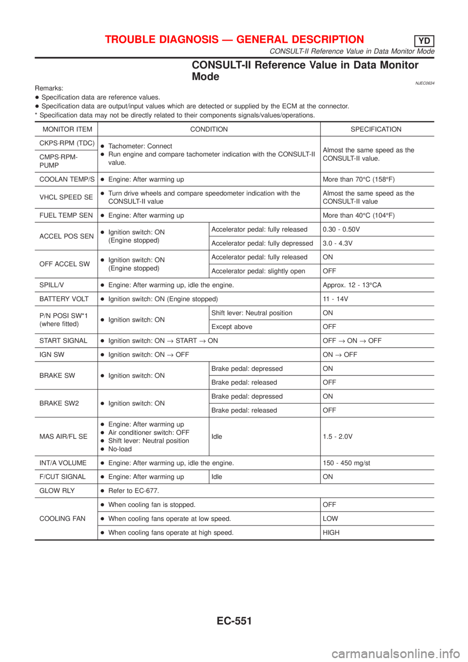
CONSULT-II Reference Value in Data Monitor
Mode
NJEC0634Remarks:
+Specification data are reference values.
+Specification data are output/input values which are detected or supplied by the ECM at the connector.
* Specification data may not be directly related to their components signals/values/operations.
MONITOR ITEM CONDITION SPECIFICATION
CKPS´RPM (TDC)
+Tachometer: Connect
+Run engine and compare tachometer indication with the CONSULT-II
value.Almost the same speed as the
CONSULT-II value. CMPS´RPM-
PUMP
COOLAN TEMP/S+Engine: After warming up More than 70ÉC (158ÉF)
VHCL SPEED SE+Turn drive wheels and compare speedometer indication with the
CONSULT-II valueAlmost the same speed as the
CONSULT-II value
FUEL TEMP SEN+Engine: After warming up More than 40ÉC (104ÉF)
ACCEL POS SEN+Ignition switch: ON
(Engine stopped)Accelerator pedal: fully released 0.30 - 0.50V
Accelerator pedal: fully depressed 3.0 - 4.3V
OFF ACCEL SW+Ignition switch: ON
(Engine stopped)Accelerator pedal: fully released ON
Accelerator pedal: slightly open OFF
SPILL/V+Engine: After warming up, idle the engine. Approx. 12 - 13ÉCA
BATTERY VOLT+Ignition switch: ON (Engine stopped) 11 - 14V
P/N POSI SW*1
(where fitted)+Ignition switch: ONShift lever: Neutral position ON
Except above OFF
START SIGNAL+Ignition switch: ON®START®ON OFF®ON®OFF
IGN SW+Ignition switch: ON®OFF ON®OFF
BRAKE SW+Ignition switch: ONBrake pedal: depressed ON
Brake pedal: released OFF
BRAKE SW2+Ignition switch: ONBrake pedal: depressed ON
Brake pedal: released OFF
MAS AIR/FL SE+Engine: After warming up
+Air conditioner switch: OFF
+Shift lever: Neutral position
+No-loadIdle 1.5 - 2.0V
INT/A VOLUME+Engine: After warming up, idle the engine. 150 - 450 mg/st
F/CUT SIGNAL+Engine: After warming up Idle ON
GLOW RLY+Refer to EC-677.
COOLING FAN+When cooling fan is stopped. OFF
+When cooling fans operate at low speed. LOW
+When cooling fans operate at high speed. HIGH
TROUBLE DIAGNOSIS Ð GENERAL DESCRIPTIONYD
CONSULT-II Reference Value in Data Monitor Mode
EC-551
Page 852 of 2493
![NISSAN ALMERA N16 2001 Electronic Owners Manual TERMI-
NAL
NO.WIRE
COLORITEM CONDITIONDATA (DC Voltage and Pulse
Signal)
337
338
350
351W/L
PU/W
GY
OR/BEGR volume control
valve[Engine is running]
+Warm-up condition
+Idle speed0.1 - 14V
(Voltage sig NISSAN ALMERA N16 2001 Electronic Owners Manual TERMI-
NAL
NO.WIRE
COLORITEM CONDITIONDATA (DC Voltage and Pulse
Signal)
337
338
350
351W/L
PU/W
GY
OR/BEGR volume control
valve[Engine is running]
+Warm-up condition
+Idle speed0.1 - 14V
(Voltage sig](/img/5/57351/w960_57351-851.png)
TERMI-
NAL
NO.WIRE
COLORITEM CONDITIONDATA (DC Voltage and Pulse
Signal)
337
338
350
351W/L
PU/W
GY
OR/BEGR volume control
valve[Engine is running]
+Warm-up condition
+Idle speed0.1 - 14V
(Voltage signals of each ECM
terminals differ according to the
control position of EGR volume
control valve.)
344 WCrankshaft position sen-
sor (TDC)[Engine is running]
+Warm-up condition
+Idle speedApproximately 0V
SEF333Y
[Engine is running]
+Warm-up condition
+Engine speed is 2,000 rpmApproximately 0V
SEF334Y
347 L/BEngine coolant tempera-
ture sensor[Engine is running]Approximately 0 - 4.8V
Output voltage varies with
engine coolant temperature
403 R/L Air conditioner switch[Engine is running]
+Air conditioner switch is ªOFFºBATTERY VOLTAGE
(11 - 14V)
[Engine is running]
+Both air conditioner switch and blower fan
switch are ªONº
(Compressor is operating)Approximately 0.1V
405 R/G Stop lamp switch[Ignition switch ªONº]
+Brake pedal fully releasedApproximately 0V
[Ignition switch ªONº]
+Brake pedal depressedBATTERY VOLTAGE
(11 - 14V)
416 Y/BBrake pedal position
switch[Ignition switch ªONº]
+Brake pedal fully releasedBATTERY VOLTAGE
(11 - 14V)
[Ignition switch ªONº]
+Brake pedal depressedApproximately 0V
TROUBLE DIAGNOSIS Ð GENERAL DESCRIPTIONYD
ECM Terminals and Reference Value (Cont'd)
EC-556
Page 893 of 2493
SEF893Y
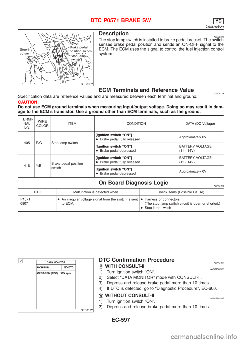
DescriptionNJEC0738The stop lamp switch is installed to brake pedal bracket. The switch
senses brake pedal position and sends an ON-OFF signal to the
ECM. The ECM uses the signal to control the fuel injection control
system.
ECM Terminals and Reference ValueNJEC0739Specification data are reference values and are measured between each terminal and ground.
CAUTION:
Do not use ECM ground terminals when measuring input/output voltage. Doing so may result in dam-
age to the ECM's transistor. Use a ground other than ECM terminals, such as the ground.
TERMI-
NAL
NO.WIRE
COLORITEM CONDITION DATA (DC Voltage)
405 R/G Stop lamp switch[Ignition switch ªONº]
+Brake pedal fully releasedApproximately 0V
[Ignition switch ªONº]
+Brake pedal depressedBATTERY VOLTAGE
(11 - 14V)
416 Y/BBrake pedal position
switch[Ignition switch ªONº]
+Brake pedal fully releasedBATTERY VOLTAGE
(11 - 14V)
[Ignition switch ªONº]
+Brake pedal depressedApproximately 0V
On Board Diagnosis LogicNJEC0740
DTC Malfunction is detected when ... Check Items (Possible Cause)
P1571
0807+An irregular voltage signal from the switch is sent
to ECM.+Harness or connectors
(The stop lamp switch circuit is open or shorted.)
+Stop lamp switch
SEF817Y
DTC Confirmation ProcedureNJEC0741WITH CONSULT-IINJEC0741S011) Turn ignition switch ªONº.
2) Select ªDATA MONITORº mode with CONSULT-II.
3) Depress and release brake pedal more than 10 times.
4) If DTC is detected, go to ªDiagnostic Procedureº, EC-600.
WITHOUT CONSULT-IINJEC0741S021) Turn ignition switch ªONº.
2) Depress and release brake pedal more than 10 times.
DTC P0571 BRAKE SWYD
Description
EC-597
Page 894 of 2493

3) Turn ignition switch ªOFFº, wait at least 5 seconds and then
turn ªONº.
4) Perform ªDiagnostic Test Mode II (Self-diagnostic results)º with
ECM.
5) If DTC is detected, go to ªDiagnostic Procedureº, EC-600.
DTC P0571 BRAKE SWYD
DTC Confirmation Procedure (Cont'd)
EC-598
Page 895 of 2493
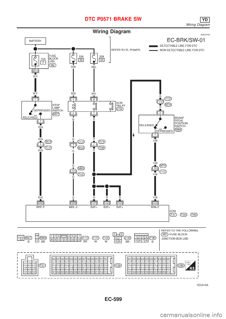
Wiring DiagramNJEC0742
YEC015A
DTC P0571 BRAKE SWYD
Wiring Diagram
EC-599
Page 896 of 2493
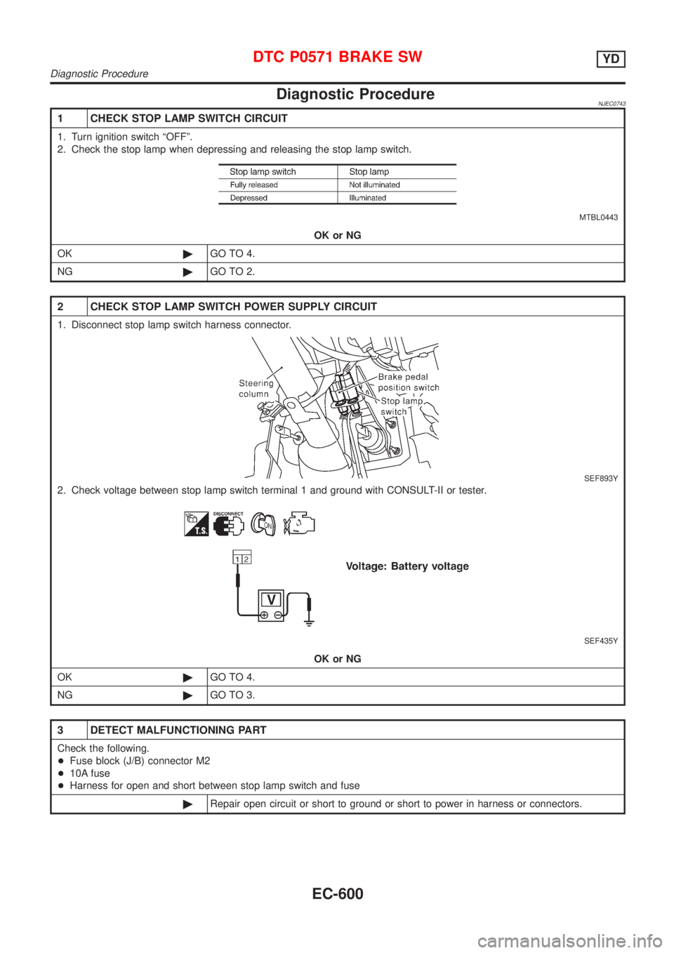
Diagnostic ProcedureNJEC0743
1 CHECK STOP LAMP SWITCH CIRCUIT
1. Turn ignition switch ªOFFº.
2. Check the stop lamp when depressing and releasing the stop lamp switch.
MTBL0443
OK or NG
OK©GO TO 4.
NG©GO TO 2.
2 CHECK STOP LAMP SWITCH POWER SUPPLY CIRCUIT
1. Disconnect stop lamp switch harness connector.
SEF893Y
2. Check voltage between stop lamp switch terminal 1 and ground with CONSULT-II or tester.
SEF435Y
OK or NG
OK©GO TO 4.
NG©GO TO 3.
3 DETECT MALFUNCTIONING PART
Check the following.
+Fuse block (J/B) connector M2
+10A fuse
+Harness for open and short between stop lamp switch and fuse
©Repair open circuit or short to ground or short to power in harness or connectors.
DTC P0571 BRAKE SWYD
Diagnostic Procedure
EC-600
Page 897 of 2493
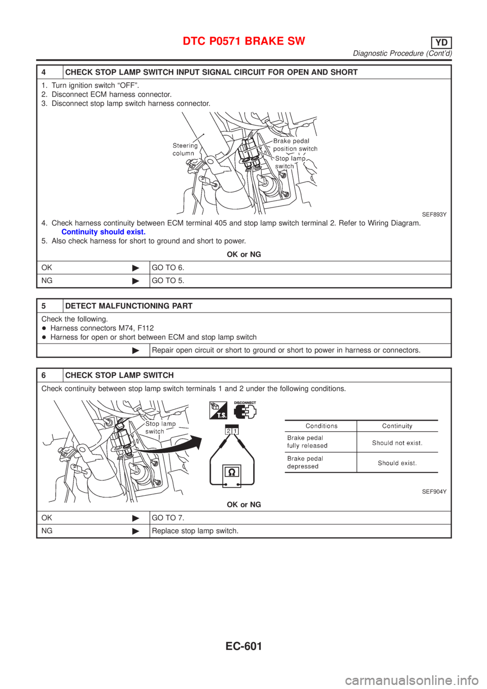
4 CHECK STOP LAMP SWITCH INPUT SIGNAL CIRCUIT FOR OPEN AND SHORT
1. Turn ignition switch ªOFFº.
2. Disconnect ECM harness connector.
3. Disconnect stop lamp switch harness connector.
SEF893Y
4. Check harness continuity between ECM terminal 405 and stop lamp switch terminal 2. Refer to Wiring Diagram.
Continuity should exist.
5. Also check harness for short to ground and short to power.
OK or NG
OK©GO TO 6.
NG©GO TO 5.
5 DETECT MALFUNCTIONING PART
Check the following.
+Harness connectors M74, F112
+Harness for open or short between ECM and stop lamp switch
©Repair open circuit or short to ground or short to power in harness or connectors.
6 CHECK STOP LAMP SWITCH
Check continuity between stop lamp switch terminals 1 and 2 under the following conditions.
SEF904Y
OK or NG
OK©GO TO 7.
NG©Replace stop lamp switch.
DTC P0571 BRAKE SWYD
Diagnostic Procedure (Cont'd)
EC-601