brake NISSAN ALMERA N16 2001 Electronic Owner's Guide
[x] Cancel search | Manufacturer: NISSAN, Model Year: 2001, Model line: ALMERA N16, Model: NISSAN ALMERA N16 2001Pages: 2493, PDF Size: 66.97 MB
Page 898 of 2493
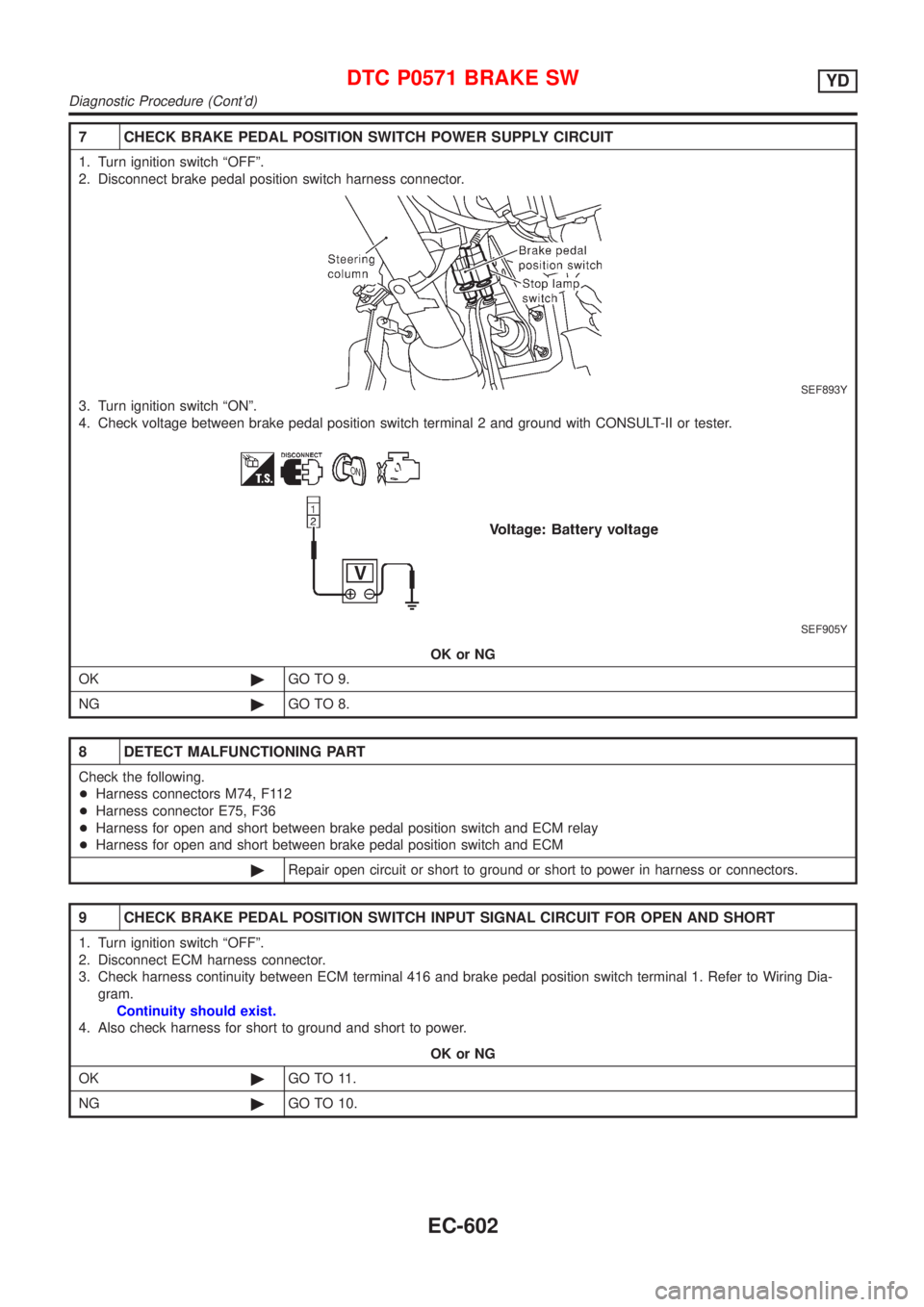
7 CHECK BRAKE PEDAL POSITION SWITCH POWER SUPPLY CIRCUIT
1. Turn ignition switch ªOFFº.
2. Disconnect brake pedal position switch harness connector.
SEF893Y
3. Turn ignition switch ªONº.
4. Check voltage between brake pedal position switch terminal 2 and ground with CONSULT-II or tester.
SEF905Y
OK or NG
OK©GO TO 9.
NG©GO TO 8.
8 DETECT MALFUNCTIONING PART
Check the following.
+Harness connectors M74, F112
+Harness connector E75, F36
+Harness for open and short between brake pedal position switch and ECM relay
+Harness for open and short between brake pedal position switch and ECM
©Repair open circuit or short to ground or short to power in harness or connectors.
9 CHECK BRAKE PEDAL POSITION SWITCH INPUT SIGNAL CIRCUIT FOR OPEN AND SHORT
1. Turn ignition switch ªOFFº.
2. Disconnect ECM harness connector.
3. Check harness continuity between ECM terminal 416 and brake pedal position switch terminal 1. Refer to Wiring Dia-
gram.
Continuity should exist.
4. Also check harness for short to ground and short to power.
OK or NG
OK©GO TO 11.
NG©GO TO 10.
DTC P0571 BRAKE SWYD
Diagnostic Procedure (Cont'd)
EC-602
Page 899 of 2493
10 DETECT MALFUNCTIONING PART
Check the following.
+Harness connectors M74, F112
+Harness for open or short between ECM and brake pedal position switch
©Repair open circuit or short to ground or short to power in harness or connectors.
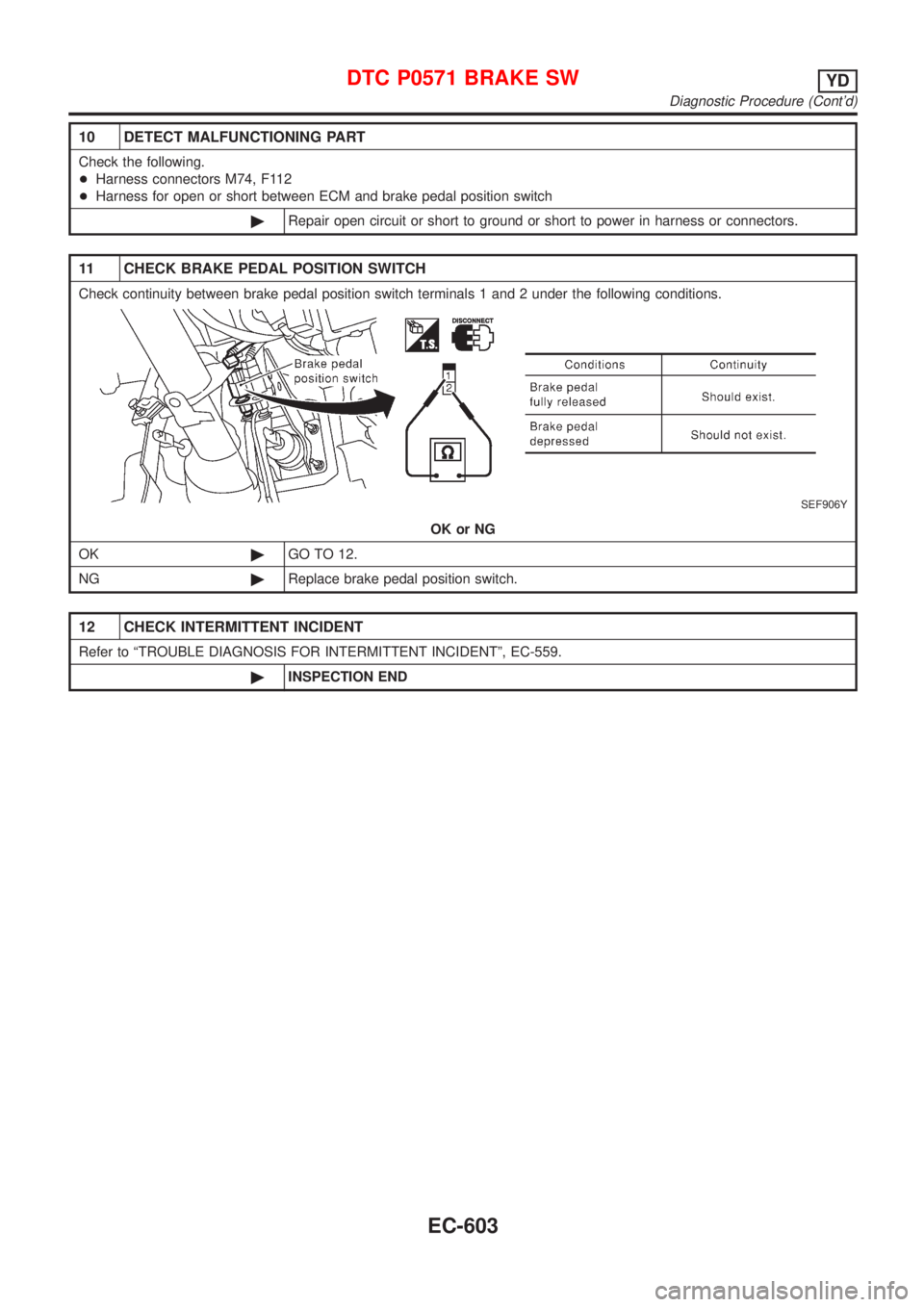
11 CHECK BRAKE PEDAL POSITION SWITCH
Check continuity between brake pedal position switch terminals 1 and 2 under the following conditions.
SEF906Y
OK or NG
OK©GO TO 12.
NG©Replace brake pedal position switch.
12 CHECK INTERMITTENT INCIDENT
Refer to ªTROUBLE DIAGNOSIS FOR INTERMITTENT INCIDENTº, EC-559.
©INSPECTION END
DTC P0571 BRAKE SWYD
Diagnostic Procedure (Cont'd)
EC-603
Page 1028 of 2493
SBR820BA
PrecautionsNJCL0001+Recommended fluid is brake fluid ªDOT 3º or ªDOT 4º
(Europe). Refer to MA-20, ªFluid and Lubricantsº.
+Never reuse drained brake fluid.
+Be careful not to splash brake fluid on painted areas.
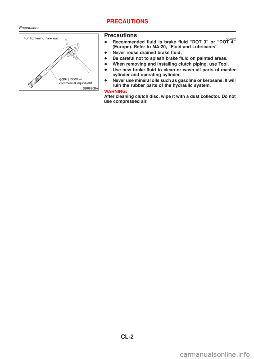
+When removing and installing clutch piping, use Tool.
+Use new brake fluid to clean or wash all parts of master
cylinder and operating cylinder.
+Never use mineral oils such as gasoline or kerosene. It will
ruin the rubber parts of the hydraulic system.
WARNING:
After cleaning clutch disc, wipe it with a dust collector. Do not
use compressed air.
PRECAUTIONS
Precautions
CL-2
Page 1036 of 2493
CLUTCH PEDAL ADJUSTMENTNJCL0006S04Pedal StrokeNJCL0006S04011. Loosen the pedal stopper bolt completely (so there is no con-
tact between pedal and stopper bolt).
2. Adjust pedal stroke to the specified value with the master cyl-
inder push rod.
3. Adjust the pedal stopper bolt until it is just in contact with the
pedal, then tighten the lock nut.
4. Once stroke is set to specification, adjust clutch pedal free
play.
Pedal stroke ªSº.
Refer to ªSDSº, CL-24.
Pedal Free PlayNJCL0006S04021. Adjust pedal free play to the specified value with the master
cylinder push rod.
2. Tighten lock nut of the master cylinder push rod.
+Push on the clutch pedal until resistance is felt, and check the
distance the pedal moves.
Pedal free play ªAº.
Refer to ªSDSº, CL-24.
SCL838
SCL839
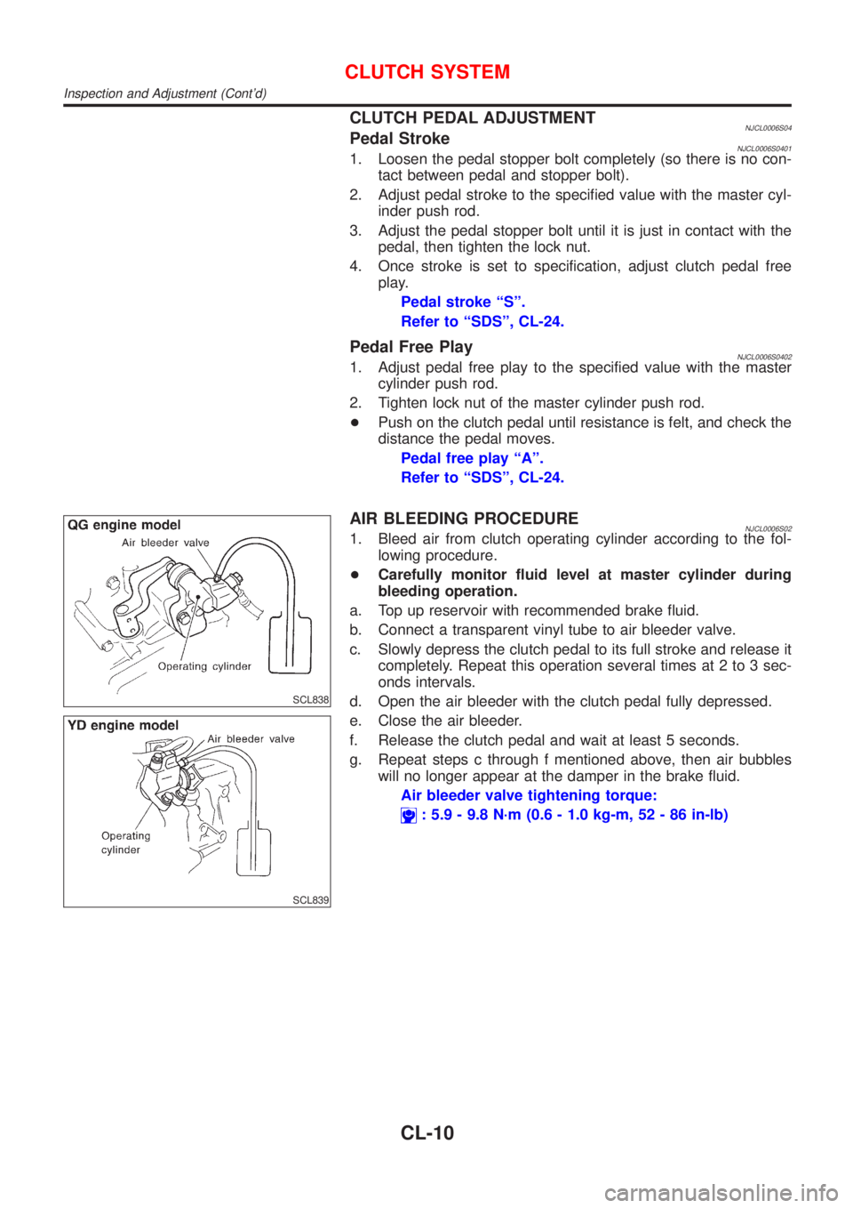
AIR BLEEDING PROCEDURENJCL0006S021. Bleed air from clutch operating cylinder according to the fol-
lowing procedure.
+Carefully monitor fluid level at master cylinder during
bleeding operation.
a. Top up reservoir with recommended brake fluid.
b. Connect a transparent vinyl tube to air bleeder valve.
c. Slowly depress the clutch pedal to its full stroke and release it
completely. Repeat this operation several times at 2 to 3 sec-
onds intervals.
d. Open the air bleeder with the clutch pedal fully depressed.
e. Close the air bleeder.
f. Release the clutch pedal and wait at least 5 seconds.
g. Repeat steps c through f mentioned above, then air bubbles
will no longer appear at the damper in the brake fluid.
Air bleeder valve tightening torque:
: 5.9 - 9.8 N´m (0.6 - 1.0 kg-m, 52 - 86 in-lb)
CLUTCH SYSTEM
Inspection and Adjustment (Cont'd)
CL-10
Page 1038 of 2493
RemovalNJCL00081. Drain brake fluid.
CAUTION:
Be careful not to splash brake fluid on painted areas; it may
cause paint damage. If brake fluid is splashed on painted
areas, wash it away with water immediately.
2. Remove clutch tube using a flare nut wrench.
3. Remove snap pin between clutch pedal and push rod, and
remove clevis pin.
4. Unscrew master cylinder assembly mounting nuts and remove
master cylinder assembly from vehicle.
InstallationNJCL00091. Connect clutch tube to master cylinder assembly, and hand-
tighten flare nut.
2. Install master cylinder assembly to vehicle, and tighten mount-
ing nuts to the specified torque.
: 11 - 14 N´m (1.1 - 1.5 kg-m,8-10ft-lb)
3. Tighten clutch tube flare nut using a flare nut torque wrench.
: 15 - 18 N´m (1.5 - 1.8 kg-m, 11 - 13 ft-lb)
4. After installing clevis pin, install snap pin to connect clutch
pedal to push rod.
5. After finishing the operation, bleed air from clutch piping con-
nector and operating cylinder. (Refer to ªAir Bleeding
Procedureº, CL-10.)
SCL725
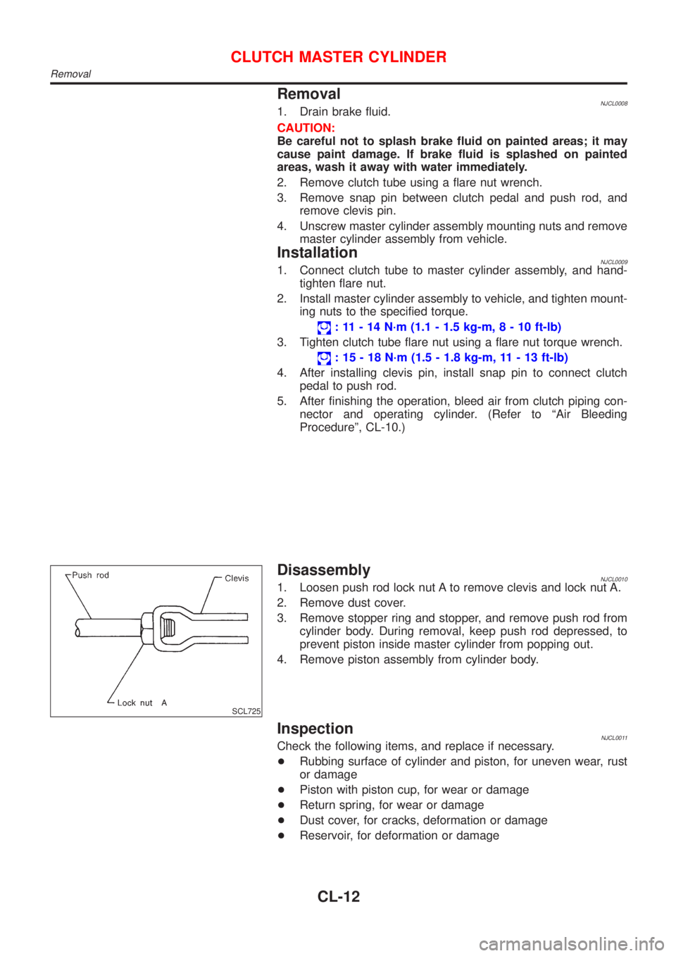
DisassemblyNJCL00101. Loosen push rod lock nut A to remove clevis and lock nut A.
2. Remove dust cover.
3. Remove stopper ring and stopper, and remove push rod from
cylinder body. During removal, keep push rod depressed, to
prevent piston inside master cylinder from popping out.
4. Remove piston assembly from cylinder body.
InspectionNJCL0011Check the following items, and replace if necessary.
+Rubbing surface of cylinder and piston, for uneven wear, rust
or damage
+Piston with piston cup, for wear or damage
+Return spring, for wear or damage
+Dust cover, for cracks, deformation or damage
+Reservoir, for deformation or damage
CLUTCH MASTER CYLINDER
Removal
CL-12
Page 1040 of 2493
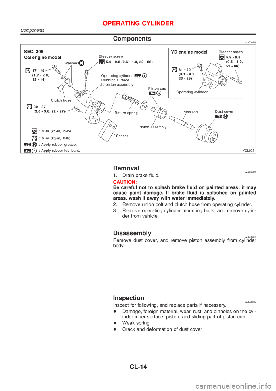
ComponentsNJCL0019
YCL003
RemovalNJCL00201. Drain brake fluid.
CAUTION:
Be careful not to splash brake fluid on painted areas; it may
cause paint damage. If brake fluid is splashed on painted
areas, wash it away with water immediately.
2. Remove union bolt and clutch hose from operating cylinder.
3. Remove operating cylinder mounting bolts, and remove cylin-
der from vehicle.
DisassemblyNJCL0021Remove dust cover, and remove piston assembly from cylinder
body.
InspectionNJCL0022Inspect for following, and replace parts if necessary.
+Damage, foreign material, wear, rust, and pinholes on the cyl-
inder inner surface, piston, and sliding part of piston cup
+Weak spring
+Crack and deformation of dust cover
OPERATING CYLINDER
Components
CL-14
Page 1042 of 2493
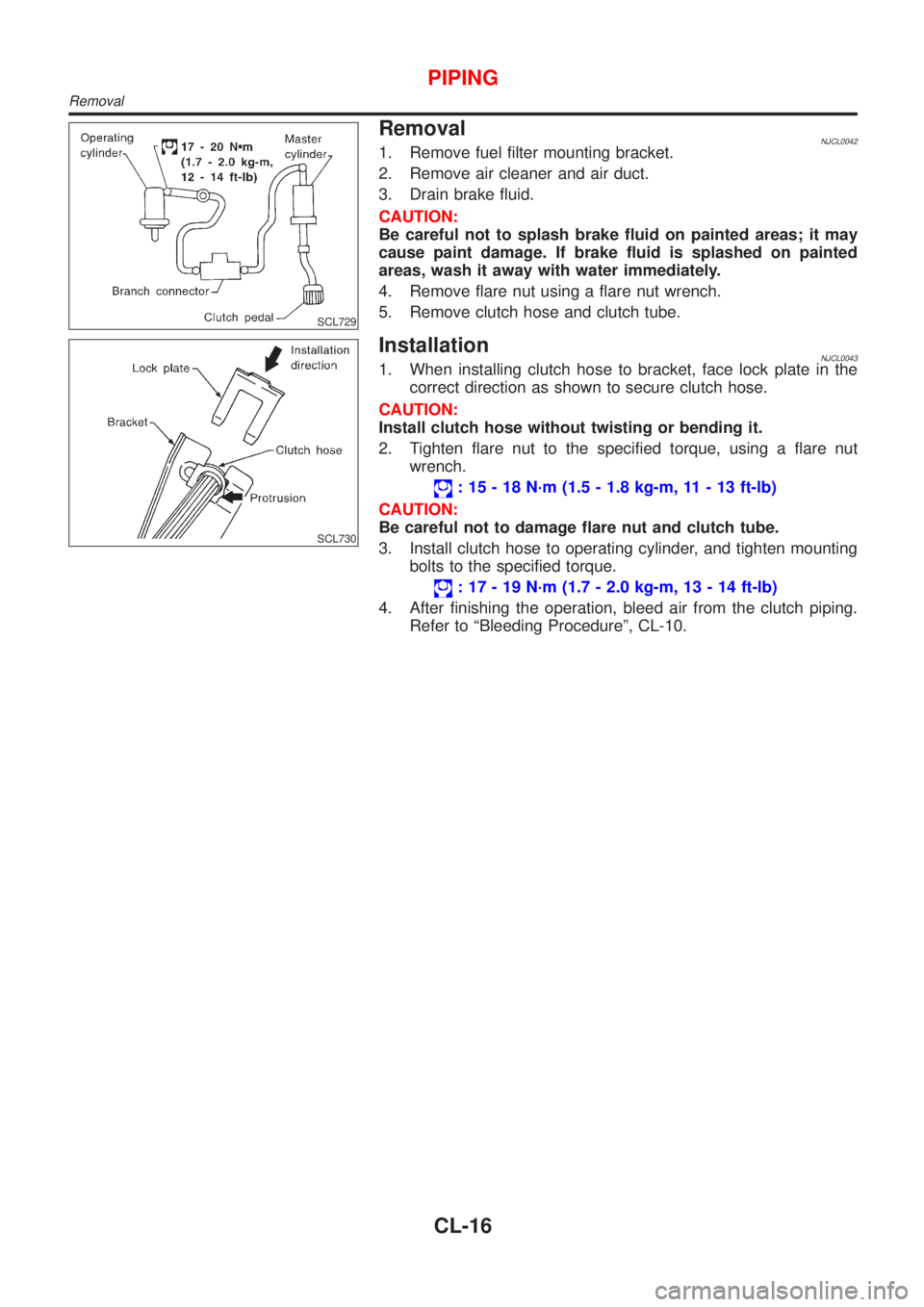
SCL729
RemovalNJCL00421. Remove fuel filter mounting bracket.
2. Remove air cleaner and air duct.
3. Drain brake fluid.
CAUTION:
Be careful not to splash brake fluid on painted areas; it may
cause paint damage. If brake fluid is splashed on painted
areas, wash it away with water immediately.
4. Remove flare nut using a flare nut wrench.
5. Remove clutch hose and clutch tube.
SCL730
InstallationNJCL00431. When installing clutch hose to bracket, face lock plate in the
correct direction as shown to secure clutch hose.
CAUTION:
Install clutch hose without twisting or bending it.
2. Tighten flare nut to the specified torque, using a flare nut
wrench.
: 15 - 18 N´m (1.5 - 1.8 kg-m, 11 - 13 ft-lb)
CAUTION:
Be careful not to damage flare nut and clutch tube.
3. Install clutch hose to operating cylinder, and tighten mounting
bolts to the specified torque.
: 17 - 19 N´m (1.7 - 2.0 kg-m, 13 - 14 ft-lb)
4. After finishing the operation, bleed air from the clutch piping.
Refer to ªBleeding Procedureº, CL-10.
PIPING
Removal
CL-16
Page 1189 of 2493
Diagnostic Procedure ..............................................253
Component Inspection .............................................255
DTC P1705 THROTTLE POSITION SENSOR...........256
Description ...............................................................256
Wiring Diagram - AT - TPS ......................................259
Diagnostic Procedure ..............................................260
Component Inspection .............................................264
DTC P1760 OVERRUN CLUTCH SOLENOID
VALVE..........................................................................265
Description ...............................................................265
Wiring Diagram - AT - OVRCSV..............................267
Diagnostic Procedure ..............................................268
Component Inspection .............................................270
DTC BATT/FLUID TEMP SEN (A/T FLUID TEMP
SENSOR CIRCUIT AND TCM POWER SOURCE)....271
Description ...............................................................271
Wiring Diagram - AT - BA/FTS ................................273
Diagnostic Procedure ..............................................274
Component Inspection .............................................277
DTC VHCL SPEED SEN.MTR VEHICLE SPEED......278
Description ...............................................................278
Wiring Diagram - AT - VSSMTR ..............................280
Diagnostic Procedure ..............................................281
DTC CONTROL UNIT (RAM), CONTROL UNIT
(ROM)...........................................................................282
Description ...............................................................282
Diagnostic Procedure ..............................................282
DTC CONTROL UNIT (EEP ROM).............................284
Description ...............................................................284
Diagnostic Procedure ..............................................285
TROUBLE DIAGNOSES FOR SYMPTOMS...............286
Wiring Diagram - AT - NONDTC .............................286
1. O/D OFF Indicator Lamp Does Not Come On....288
2. Engine Cannot Be Started In²P²and²N²
Position ....................................................................291
3. In²P²Position, Vehicle Moves Forward Or
Backward When Pushed .........................................292
4. In²N²Position, Vehicle Moves ...........................293
5. Large Shock.²N²->²R²Position .......................295
6. Vehicle Does Not Creep Backward In²R²
Position ....................................................................297
7. Vehicle Does Not Creep Forward In²D²,²2²
Or²1²Position .........................................................300
8. Vehicle Cannot Be Started From D
1...................303
9. A/T Does Not Shift: D
1-> D2Or Does Not
Kickdown: D
4-> D2..................................................306
10. A/T Does Not Shift: D
2-> D3.............................309
11. A/T Does Not Shift: D
3-> D4.............................312
12. A/T Does Not Perform Lock-up .........................315
13. A/T Does Not Hold Lock-up Condition ..............31714. Lock-up Is Not Released ...................................319
15. Engine Speed Does Not Return To Idle (Light
Braking D
4-> D3).....................................................320
16. Vehicle Does Not Start From D
1.......................322
17. A/T Does Not Shift: D
4-> D3, When
Overdrive Control Switch²ON²->²OFF²...............323
18. A/T Does Not Shift: D
3-> 22, When Selector
Lever²D²->²2²Position.........................................324
19. A/T Does Not Shift: 2
2-> 11, When Selector
Lever²2²->²1²Position .........................................325
20. Vehicle Does Not Decelerate By Engine
Brake........................................................................326
21. TCM Self-diagnosis Does Not Activate (PNP,
Overdrive Control and Throttle Position Switches
Circuit Checks) ........................................................326
A/T SHIFT LOCK SYSTEM.........................................335
Description ...............................................................335
Shift Lock System Electrical Parts Location............335
Wiring Diagram - SHIFT -........................................336
Diagnostic Procedure ..............................................337
KEY INTERLOCK CABLE..........................................341
Components.............................................................341
Removal ...................................................................341
Installation ................................................................342
ON-VEHICLE SERVICE..............................................343
Control Valve Assembly and Accumulators .............343
Control Cable Adjustment ........................................344
Park/Neutral Position (PNP) Switch Adjustment .....344
Differential Side Oil Seal Replacement ...................345
Revolution Sensor Replacement .............................345
REMOVAL AND INSTALLATION...............................346
Removal ...................................................................346
Installation ................................................................347
OVERHAUL.................................................................349
Components-1 .........................................................349
Components-2 .........................................................350
Components-3 .........................................................351
Oil Channel ..............................................................352
Locations of Adjusting Shims, Needle Bearings,
Thrust Washers and Snap Rings ............................353
DISASSEMBLY............................................................354
REPAIR FOR COMPONENT PARTS.........................368
Manual Shaft............................................................368
Oil Pump ..................................................................371
Control Valve Assembly ...........................................375
Control Valve Upper Body .......................................384
Control Valve Lower Body .......................................388
Reverse Clutch ........................................................390
High Clutch ..............................................................394
Forward Clutch and Overrun Clutch........................399
Low & Reverse Brake..............................................406
CONTENTS(Cont'd)
AT-3
Page 1190 of 2493
Rear Internal Gear, Forward Clutch Hub and
Overrun Clutch Hub .................................................410
Output Shaft, Idler Gear, Reduction Pinion Gear
and Bearing Retainer...............................................414
Band Servo Piston Assembly ..................................419
Final Drive................................................................424
ASSEMBLY..................................................................428
Assembly (1) ............................................................428
Adjustment (1) .........................................................429
Assembly (2) ............................................................434
Adjustment (2) .........................................................438
Assembly (3) ............................................................442
Assembly (4) ............................................................444
SERVICE DATA AND SPECIFICATIONS (SDS).......449
General Specifications .............................................449
Shift Schedule..........................................................449
Stall Revolution ........................................................450
Line Pressure...........................................................450
Control Valves..........................................................450Clutch and Brakes ...................................................451
Clutch and Brake Return Springs............................452
Oil Pump ..................................................................453
Input Shaft ...............................................................453
Planetary Carrier......................................................453
Final Drive................................................................453
Reduction Pinion Gear ............................................455
Output Shaft.............................................................456
Bearing Retainer ......................................................457
Total End Play..........................................................457
Reverse Clutch End Play ........................................457
Accumulator .............................................................457
Band Servo ..............................................................458
Removal and Installation .........................................458
Shift Solenoid Valves ...............................................458
Resistance ...............................................................458
ATF Temp. Sensor ...................................................458
Revolution Sensor ...................................................458
Dropping Resistor ....................................................458
CONTENTS(Cont'd)
AT-4
Page 1201 of 2493
SMA827CA
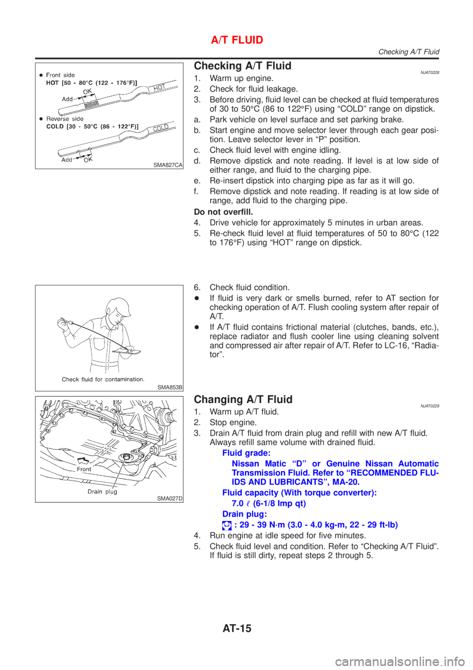
Checking A/T FluidNJAT02281. Warm up engine.
2. Check for fluid leakage.
3. Before driving, fluid level can be checked at fluid temperatures
of 30 to 50ÉC (86 to 122ÉF) using ªCOLDº range on dipstick.
a. Park vehicle on level surface and set parking brake.
b. Start engine and move selector lever through each gear posi-
tion. Leave selector lever in ªPº position.
c. Check fluid level with engine idling.
d. Remove dipstick and note reading. If level is at low side of
either range, and fluid to the charging pipe.
e. Re-insert dipstick into charging pipe as far as it will go.
f. Remove dipstick and note reading. If reading is at low side of
range, add fluid to the charging pipe.
Do not overfill.
4. Drive vehicle for approximately 5 minutes in urban areas.
5. Re-check fluid level at fluid temperatures of 50 to 80ÉC (122
to 176ÉF) using ªHOTº range on dipstick.
SMA853B
6. Check fluid condition.
+If fluid is very dark or smells burned, refer to AT section for
checking operation of A/T. Flush cooling system after repair of
A/T.
+If A/T fluid contains frictional material (clutches, bands, etc.),
replace radiator and flush cooler line using cleaning solvent
and compressed air after repair of A/T. Refer to LC-16, ªRadia-
torº.
SMA027D
Changing A/T FluidNJAT02291. Warm up A/T fluid.
2. Stop engine.
3. Drain A/T fluid from drain plug and refill with new A/T fluid.
Always refill same volume with drained fluid.
Fluid grade:
Nissan Matic ªDº or Genuine Nissan Automatic
Transmission Fluid. Refer to ªRECOMMENDED FLU-
IDS AND LUBRICANTSº, MA-20.
Fluid capacity (With torque converter):
7.0!(6-1/8 Imp qt)
Drain plug:
: 29 - 39 N´m (3.0 - 4.0 kg-m, 22 - 29 ft-lb)
4. Run engine at idle speed for five minutes.
5. Check fluid level and condition. Refer to ªChecking A/T Fluidº.
If fluid is still dirty, repeat steps 2 through 5.
A/T FLUID
Checking A/T Fluid
AT-15