brake NISSAN ALMERA N16 2001 Electronic Service Manual
[x] Cancel search | Manufacturer: NISSAN, Model Year: 2001, Model line: ALMERA N16, Model: NISSAN ALMERA N16 2001Pages: 2493, PDF Size: 66.97 MB
Page 1206 of 2493
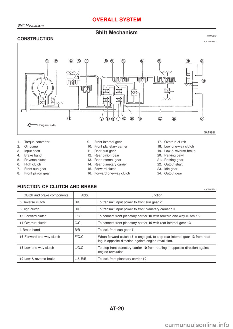
Shift MechanismNJAT0013CONSTRUCTIONNJAT0013S01
SAT998I
1. Torque converter
2. Oil pump
3. Input shaft
4. Brake band
5. Reverse clutch
6. High clutch
7. Front sun gear
8. Front pinion gear9. Front internal gear
10. Front planetary carrier
11. Rear sun gear
12. Rear pinion gear
13. Rear internal gear
14. Rear planetary carrier
15. Forward clutch
16. Forward one-way clutch17. Overrun clutch
18. Low one-way clutch
19. Low & reverse brake
20. Parking pawl
21. Parking gear
22. Output shaft
23. Idle gear
24. Output gear
FUNCTION OF CLUTCH AND BRAKENJAT0013S03
Clutch and brake components Abbr. Function
5Reverse clutch R/C To transmit input power to front sun gear7.
6High clutch H/C To transmit input power to front planetary carrier10.
15Forward clutch F/C To connect front planetary carrier10with forward one-way clutch16.
17Overrun clutch O/C To connect front planetary carrier10with rear internal gear13.
4Brake band B/B To lock front sun gear7.
16Forward one-way clutch F/O.C When forward clutch15is engaged, to stop rear internal gear13from rotat-
ing in opposite direction against engine revolution.
18Low one-way clutch L/O.C To stop front planetary carrier10from rotating in opposite direction against
engine revolution.
19Low & reverse brake L & R/B To lock front planetary carrier10.
OVERALL SYSTEM
Shift Mechanism
AT-20
Page 1207 of 2493
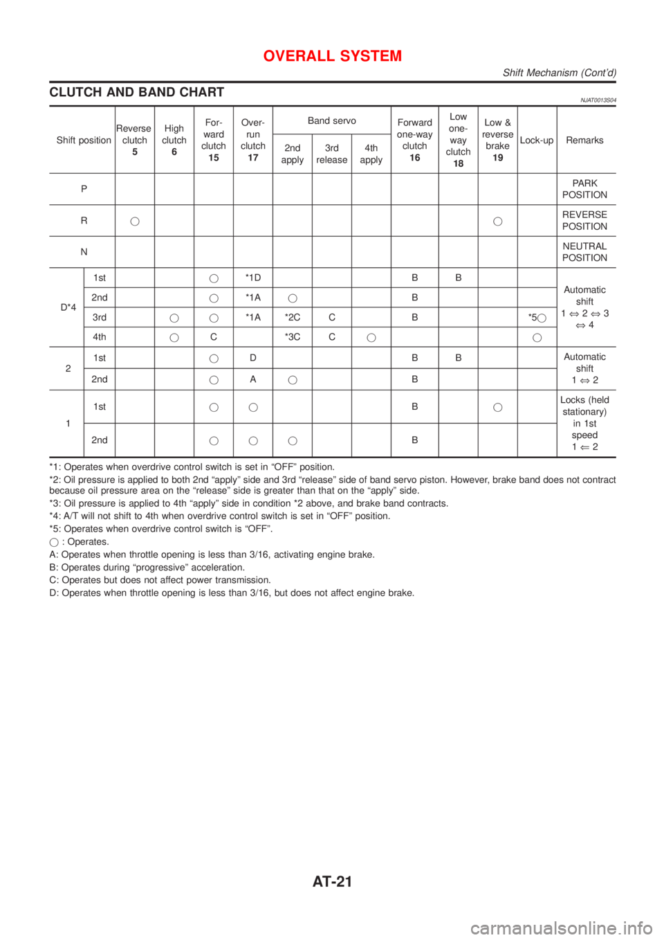
CLUTCH AND BAND CHARTNJAT0013S04
Shift positionReverse
clutch
5High
clutch
6For-
ward
clutch
15Over-
run
clutch
17Band servo
Forward
one-way
clutch
16Low
one-
way
clutch
18Low &
reverse
brake
19Lock-up Remarks
2nd
apply3rd
release4th
apply
PPARK
POSITION
RjjREVERSE
POSITION
NNEUTRAL
POSITION
D*41stj*1D B B
Automatic
shift
1Û2Û3
Û4 2ndj*1AjB
3rdjj*1A *2C C B *5j
4thjC *3C Cjj
21stjDBBAutomatic
shift
1Û2 2ndjAjB
11stjjBjLocks (held
stationary)
in 1st
speed
1Ü2 2ndjjjB
*1: Operates when overdrive control switch is set in ªOFFº position.
*2: Oil pressure is applied to both 2nd ªapplyº side and 3rd ªreleaseº side of band servo piston. However, brake band does not contract
because oil pressure area on the ªreleaseº side is greater than that on the ªapplyº side.
*3: Oil pressure is applied to 4th ªapplyº side in condition *2 above, and brake band contracts.
*4: A/T will not shift to 4th when overdrive control switch is set in ªOFFº position.
*5: Operates when overdrive control switch is ªOFFº.
j: Operates.
A: Operates when throttle opening is less than 3/16, activating engine brake.
B: Operates during ªprogressiveº acceleration.
C: Operates but does not affect power transmission.
D: Operates when throttle opening is less than 3/16, but does not affect engine brake.
OVERALL SYSTEM
Shift Mechanism (Cont'd)
AT-21
Page 1209 of 2493
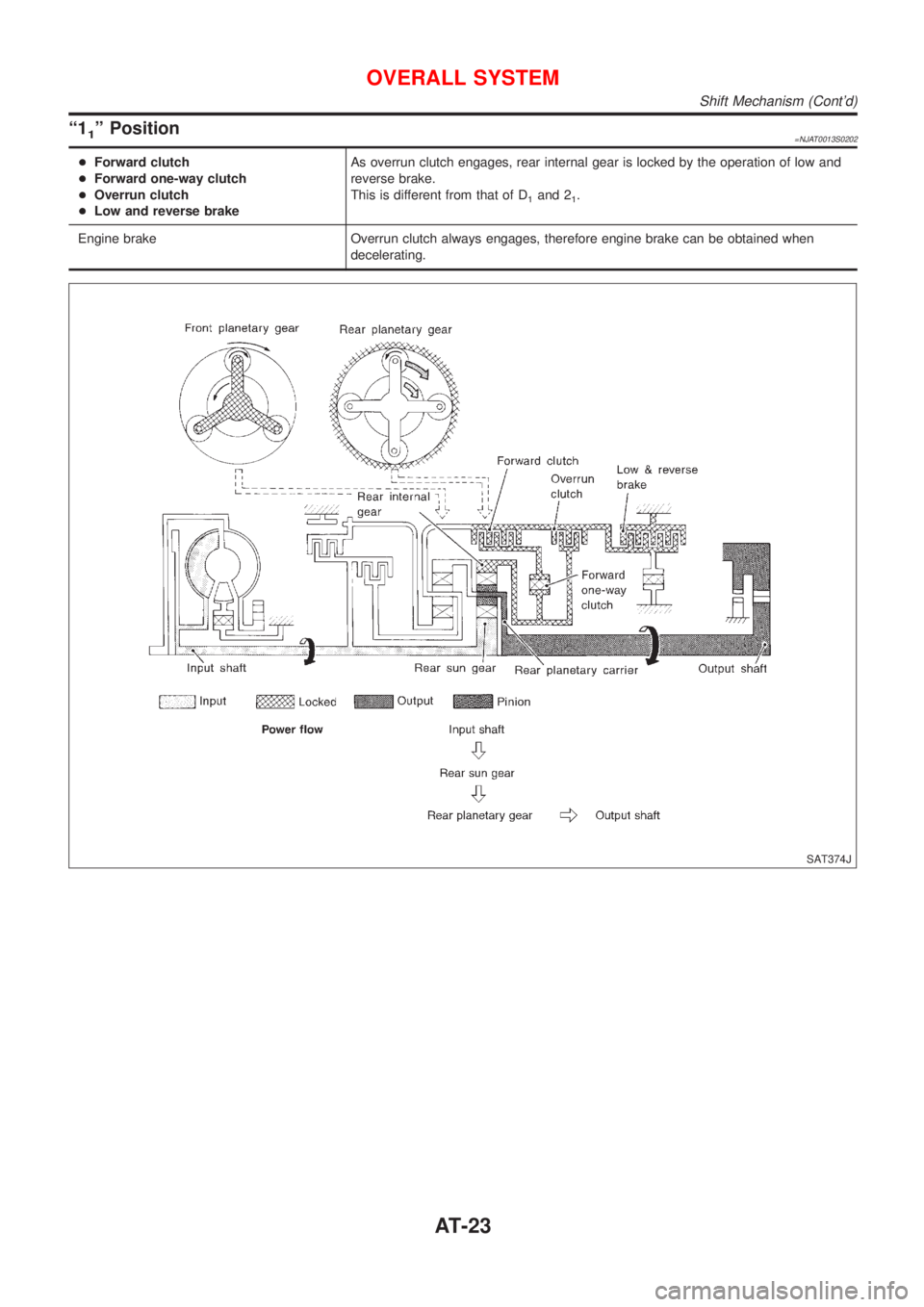
ª11º Position=NJAT0013S0202
+Forward clutch
+Forward one-way clutch
+Overrun clutch
+Low and reverse brakeAs overrun clutch engages, rear internal gear is locked by the operation of low and
reverse brake.
This is different from that of D
1and 21.
Engine brake Overrun clutch always engages, therefore engine brake can be obtained when
decelerating.
SAT374J
OVERALL SYSTEM
Shift Mechanism (Cont'd)
AT-23
Page 1210 of 2493
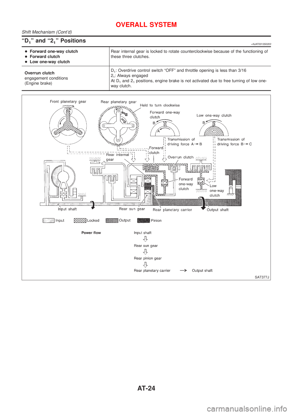
ªD1º and ª21º Positions=NJAT0013S0203
+Forward one-way clutch
+Forward clutch
+Low one-way clutchRear internal gear is locked to rotate counterclockwise because of the functioning of
these three clutches.
Overrun clutch
engagement conditions
(Engine brake)D
1: Overdrive control switch ªOFFº and throttle opening is less than 3/16
2
1: Always engaged
At D
1and 21positions, engine brake is not activated due to free turning of low one-
way clutch.
SAT377J
OVERALL SYSTEM
Shift Mechanism (Cont'd)
AT-24
Page 1211 of 2493
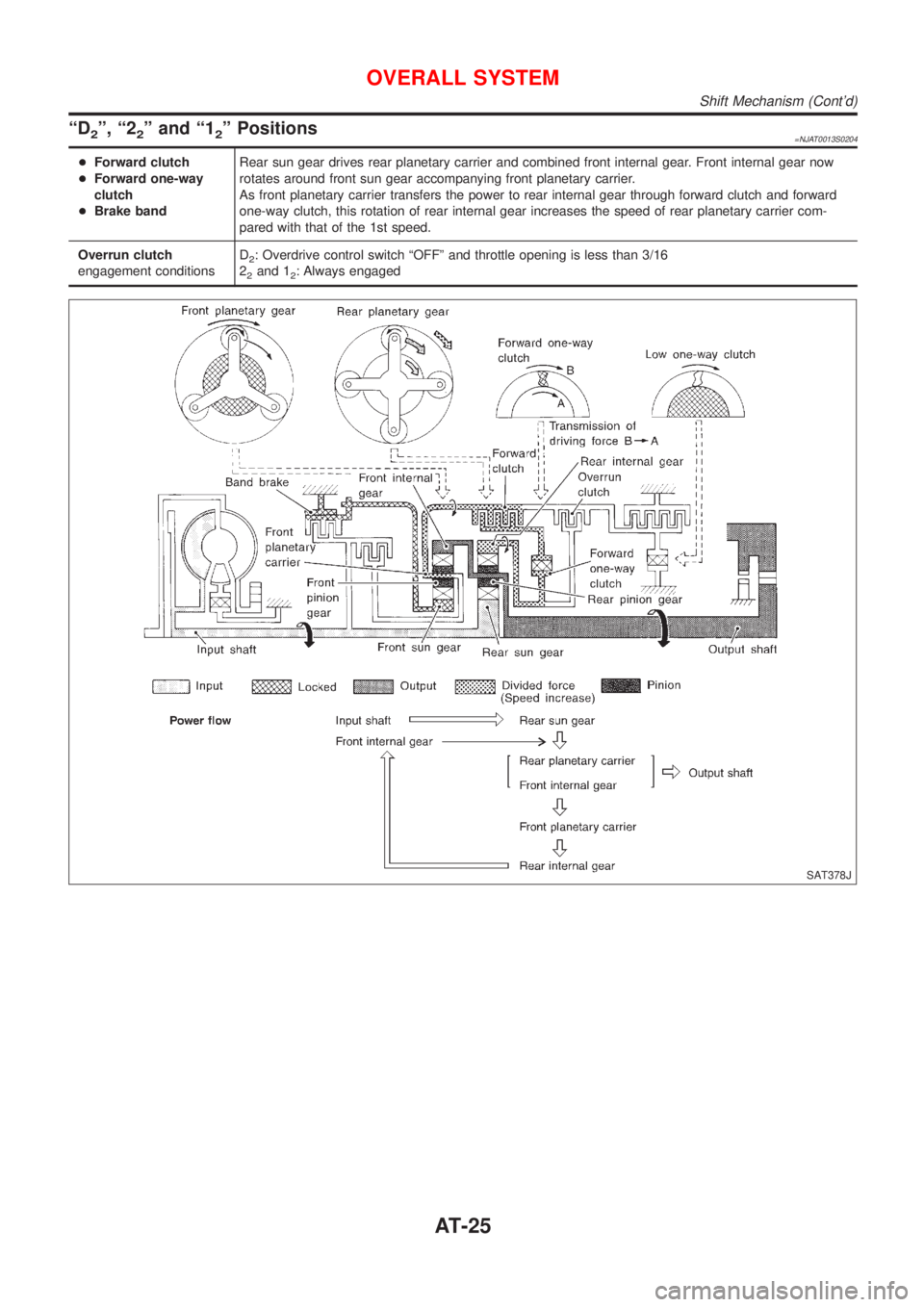
ªD2º, ª22º and ª12º Positions=NJAT0013S0204
+Forward clutch
+Forward one-way
clutch
+Brake bandRear sun gear drives rear planetary carrier and combined front internal gear. Front internal gear now
rotates around front sun gear accompanying front planetary carrier.
As front planetary carrier transfers the power to rear internal gear through forward clutch and forward
one-way clutch, this rotation of rear internal gear increases the speed of rear planetary carrier com-
pared with that of the 1st speed.
Overrun clutch
engagement conditionsD
2: Overdrive control switch ªOFFº and throttle opening is less than 3/16
2
2and 12: Always engaged
SAT378J
OVERALL SYSTEM
Shift Mechanism (Cont'd)
AT-25
Page 1213 of 2493
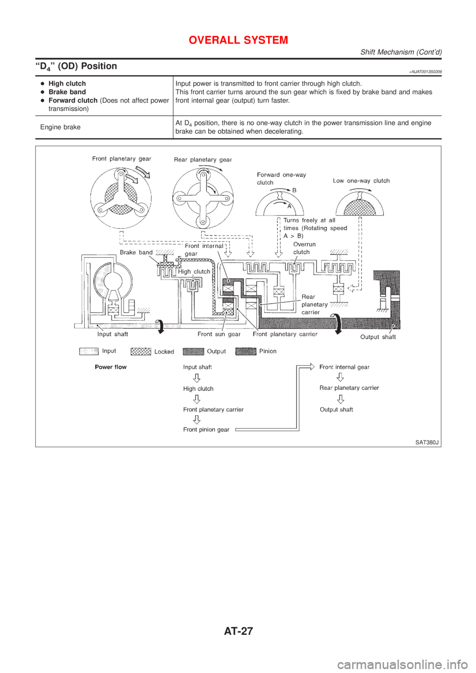
ªD4º (OD) Position=NJAT0013S0206
+High clutch
+Brake band
+Forward clutch(Does not affect power
transmission)Input power is transmitted to front carrier through high clutch.
This front carrier turns around the sun gear which is fixed by brake band and makes
front internal gear (output) turn faster.
Engine brakeAt D
4position, there is no one-way clutch in the power transmission line and engine
brake can be obtained when decelerating.
SAT380J
OVERALL SYSTEM
Shift Mechanism (Cont'd)
AT-27
Page 1214 of 2493
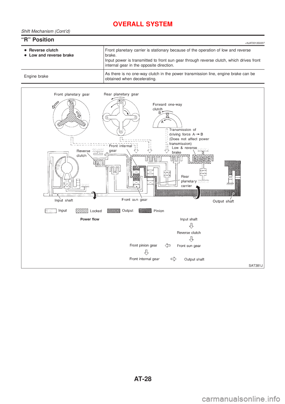
ªRº Position=NJAT0013S0207
+Reverse clutch
+Low and reverse brakeFront planetary carrier is stationary because of the operation of low and reverse
brake.
Input power is transmitted to front sun gear through reverse clutch, which drives front
internal gear in the opposite direction.
Engine brakeAs there is no one-way clutch in the power transmission line, engine brake can be
obtained when decelerating.
SAT381J
OVERALL SYSTEM
Shift Mechanism (Cont'd)
AT-28
Page 1216 of 2493
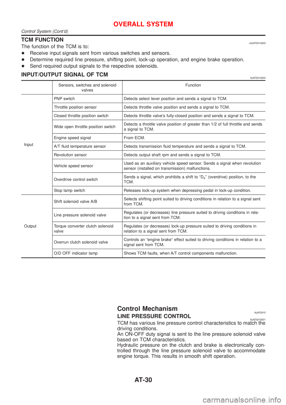
TCM FUNCTION=NJAT0014S03The function of the TCM is to:
+Receive input signals sent from various switches and sensors.
+Determine required line pressure, shifting point, lock-up operation, and engine brake operation.
+Send required output signals to the respective solenoids.
INPUT/OUTPUT SIGNAL OF TCMNJAT0014S04
Sensors, switches and solenoid
valvesFunction
InputPNP switch Detects select lever position and sends a signal to TCM.
Throttle position sensor Detects throttle valve position and sends a signal to TCM.
Closed throttle position switch Detects throttle valve's fully-closed position and sends a signal to TCM.
Wide open throttle position switchDetects a throttle valve position of greater than 1/2 of full throttle and sends
a signal to TCM.
Engine speed signal From ECM.
A/T fluid temperature sensor Detects transmission fluid temperature and sends a signal to TCM.
Revolution sensor Detects output shaft rpm and sends a signal to TCM.
Vehicle speed sensorUsed as an auxiliary vehicle speed sensor. Sends a signal when revolution
sensor (installed on transmission) malfunctions.
Overdrive control switchSends a signal, which prohibits a shift to ªD
4º (overdrive) position, to the
TCM.
Stop lamp switch Releases lock-up system when depressing pedal in lock-up condition.
OutputShift solenoid valve A/BSelects shifting point suited to driving conditions in relation to a signal sent
from TCM.
Line pressure solenoid valveRegulates (or decreases) line pressure suited to driving conditions in rela-
tion to a signal sent from TCM.
Torque converter clutch solenoid
valveRegulates (or decreases) lock-up pressure suited to driving conditions in
relation to a signal sent from TCM.
Overrun clutch solenoid valveControls an ªengine brakeº effect suited to driving conditions in relation to a
signal sent from TCM.
O/D OFF indicator lamp Shows TCM faults, when A/T control components malfunction.
Control MechanismNJAT0015LINE PRESSURE CONTROLNJAT0015S01TCM has various line pressure control characteristics to match the
driving conditions.
An ON-OFF duty signal is sent to the line pressure solenoid valve
based on TCM characteristics.
Hydraulic pressure on the clutch and brake is electronically con-
trolled through the line pressure solenoid valve to accommodate
engine torque. This results in smooth shift operation.
OVERALL SYSTEM
Control System (Cont'd)
AT-30
Page 1217 of 2493
SAT003J
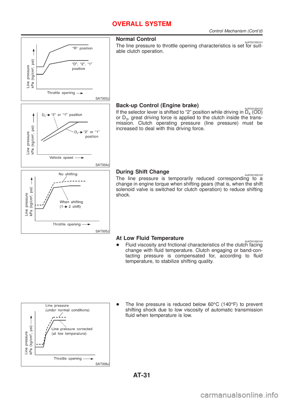
Normal ControlNJAT0015S0101The line pressure to throttle opening characteristics is set for suit-
able clutch operation.
SAT004J
Back-up Control (Engine brake)NJAT0015S0102If the selector lever is shifted to ª2º position while driving in D4(OD)
or D
3, great driving force is applied to the clutch inside the trans-
mission. Clutch operating pressure (line pressure) must be
increased to deal with this driving force.
SAT005J
During Shift ChangeNJAT0015S0103The line pressure is temporarily reduced corresponding to a
change in engine torque when shifting gears (that is, when the shift
solenoid valve is switched for clutch operation) to reduce shifting
shock.
At Low Fluid TemperatureNJAT0015S0104+Fluid viscosity and frictional characteristics of the clutch facing
change with fluid temperature. Clutch engaging or band-con-
tacting pressure is compensated for, according to fluid
temperature, to stabilize shifting quality.
SAT006J
+The line pressure is reduced below 60ÉC (140ÉF) to prevent
shifting shock due to low viscosity of automatic transmission
fluid when temperature is low.
OVERALL SYSTEM
Control Mechanism (Cont'd)
AT-31
Page 1218 of 2493
SAT007J
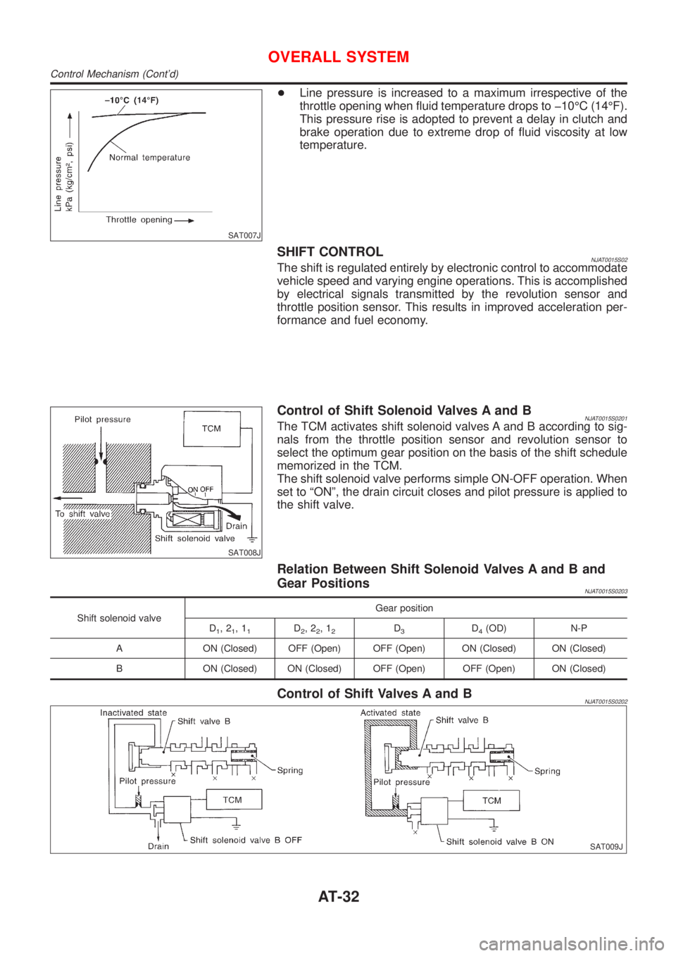
+Line pressure is increased to a maximum irrespective of the
throttle opening when fluid temperature drops to þ10ÉC (14ÉF).
This pressure rise is adopted to prevent a delay in clutch and
brake operation due to extreme drop of fluid viscosity at low
temperature.
SHIFT CONTROLNJAT0015S02The shift is regulated entirely by electronic control to accommodate
vehicle speed and varying engine operations. This is accomplished
by electrical signals transmitted by the revolution sensor and
throttle position sensor. This results in improved acceleration per-
formance and fuel economy.
SAT008J
Control of Shift Solenoid Valves A and BNJAT0015S0201The TCM activates shift solenoid valves A and B according to sig-
nals from the throttle position sensor and revolution sensor to
select the optimum gear position on the basis of the shift schedule
memorized in the TCM.
The shift solenoid valve performs simple ON-OFF operation. When
set to ªONº, the drain circuit closes and pilot pressure is applied to
the shift valve.
Relation Between Shift Solenoid Valves A and B and
Gear Positions
NJAT0015S0203
Shift solenoid valveGear position
D
1,21,11D2,22,12D3D4(OD) N-P
A ON (Closed) OFF (Open) OFF (Open) ON (Closed) ON (Closed)
B ON (Closed) ON (Closed) OFF (Open) OFF (Open) ON (Closed)
Control of Shift Valves A and BNJAT0015S0202
SAT009J
OVERALL SYSTEM
Control Mechanism (Cont'd)
AT-32