lug NISSAN ALMERA N16 2001 Electronic Owner's Guide
[x] Cancel search | Manufacturer: NISSAN, Model Year: 2001, Model line: ALMERA N16, Model: NISSAN ALMERA N16 2001Pages: 2493, PDF Size: 66.97 MB
Page 267 of 2493
SMA182B
SMA412B
Refer to MA-20, ªRECOMMENDED FLUIDS AND LUBRI-
CANTSº.
Coolant capacity (With reservoir tank):
Unit:!(Imp qt)
M/T 6.7 (5-7/8)
A/TFor Sedan 6.6 (5-7/8)
For Hatchback 6.7 (5-7/8)
Reservoir tank capacity:
0.7!(5/8 Imp qt)
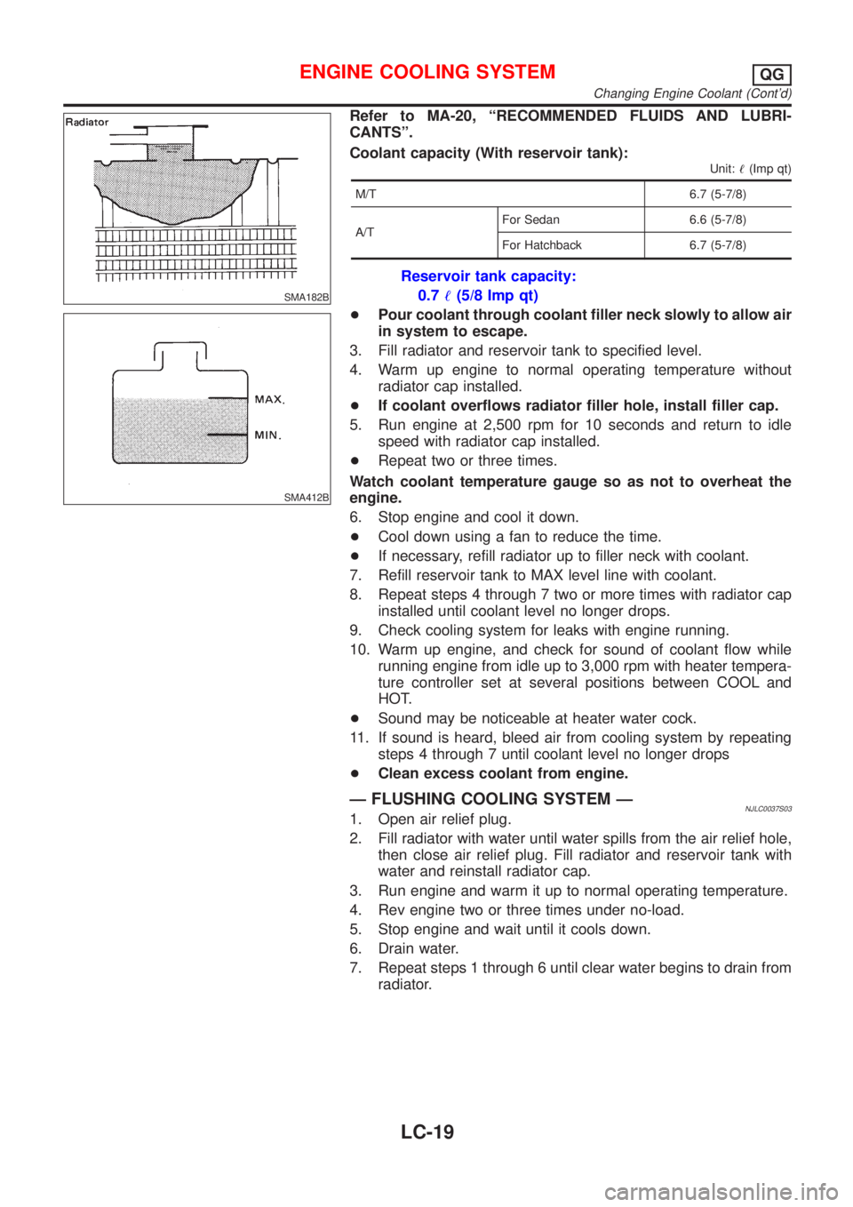
+Pour coolant through coolant filler neck slowly to allow air
in system to escape.
3. Fill radiator and reservoir tank to specified level.
4. Warm up engine to normal operating temperature without
radiator cap installed.
+If coolant overflows radiator filler hole, install filler cap.
5. Run engine at 2,500 rpm for 10 seconds and return to idle
speed with radiator cap installed.
+Repeat two or three times.
Watch coolant temperature gauge so as not to overheat the
engine.
6. Stop engine and cool it down.
+Cool down using a fan to reduce the time.
+If necessary, refill radiator up to filler neck with coolant.
7. Refill reservoir tank to MAX level line with coolant.
8. Repeat steps 4 through 7 two or more times with radiator cap
installed until coolant level no longer drops.
9. Check cooling system for leaks with engine running.
10. Warm up engine, and check for sound of coolant flow while
running engine from idle up to 3,000 rpm with heater tempera-
ture controller set at several positions between COOL and
HOT.
+Sound may be noticeable at heater water cock.
11. If sound is heard, bleed air from cooling system by repeating
steps 4 through 7 until coolant level no longer drops
+Clean excess coolant from engine.
Ð FLUSHING COOLING SYSTEM ÐNJLC0037S031. Open air relief plug.
2. Fill radiator with water until water spills from the air relief hole,
then close air relief plug. Fill radiator and reservoir tank with
water and reinstall radiator cap.
3. Run engine and warm it up to normal operating temperature.
4. Rev engine two or three times under no-load.
5. Stop engine and wait until it cools down.
6. Drain water.
7. Repeat steps 1 through 6 until clear water begins to drain from
radiator.
ENGINE COOLING SYSTEMQG
Changing Engine Coolant (Cont'd)
LC-19
Page 278 of 2493
SLC287B
JLC288B
Changing Engine OilNJLC0074WARNING:
+Be careful not to burn yourself, as the engine oil is hot.
+Prolonged and repeated contact with used engine oil may
cause skin cancer; try to avoid direct skin contact with
used oil. If skin contact is made, wash thoroughly with
soap or hand cleaner as soon as possible.
1. Warm up engine, and check for oil leakage from engine com-
ponents.
2. Stop engine and wait more than 10 minutes.
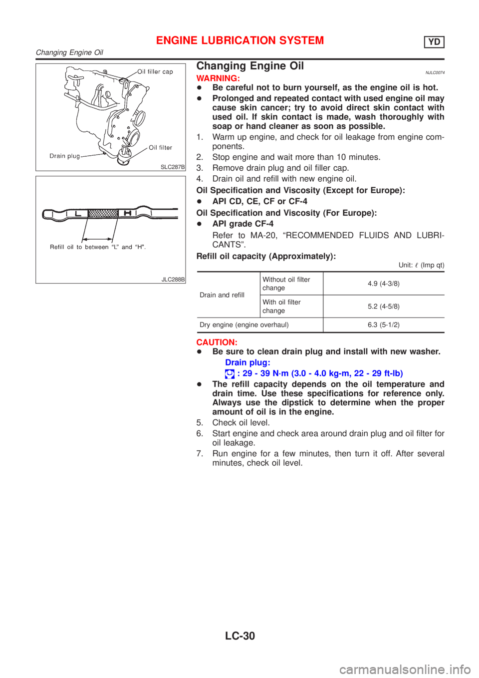
3. Remove drain plug and oil filler cap.
4. Drain oil and refill with new engine oil.
Oil Specification and Viscosity (Except for Europe):
+API CD, CE, CF or CF-4
Oil Specification and Viscosity (For Europe):
+API grade CF-4
Refer to MA-20, ªRECOMMENDED FLUIDS AND LUBRI-
CANTSº.
Refill oil capacity (Approximately):
Unit:!(Imp qt)
Drain and refillWithout oil filter
change4.9 (4-3/8)
With oil filter
change5.2 (4-5/8)
Dry engine (engine overhaul) 6.3 (5-1/2)
CAUTION:
+Be sure to clean drain plug and install with new washer.
Drain plug:
: 29 - 39 N´m (3.0 - 4.0 kg-m, 22 - 29 ft-lb)
+The refill capacity depends on the oil temperature and
drain time. Use these specifications for reference only.
Always use the dipstick to determine when the proper
amount of oil is in the engine.
5. Check oil level.
6. Start engine and check area around drain plug and oil filter for
oil leakage.
7. Run engine for a few minutes, then turn it off. After several
minutes, check oil level.
ENGINE LUBRICATION SYSTEMYD
Changing Engine Oil
LC-30
Page 291 of 2493
JLC295B
Changing Engine CoolantNJLC0079WARNING:
To avoid the danger of being scalded, never change the cool-
ant when the engine is hot.
Ð DRAINING ENGINE COOLANT ÐNJLC0079S011. Set air conditioning system as follows to prevent coolant from
remaining in the system.
a. Turn ignition switch ON and set temperature controller to maxi-
mum hot position.
b. Wait 10 seconds before turning ignition switch OFF.
SMA033D
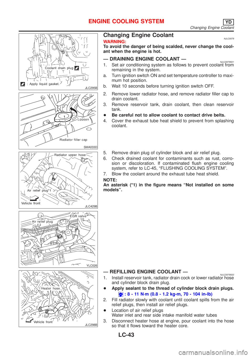
2. Remove lower radiator hose, and remove radiator filler cap to
drain coolant.
3. Remove reservoir tank, drain coolant, then clean reservoir
tank.
+Be careful not to allow coolant to contact drive belts.
4. Cover the exhaust tube heat shield to prevent from splashing
coolant.
JLC429B
YLC026
5. Remove drain plug of cylinder block and air relief plug.
6. Check drained coolant for contaminants such as rust, corro-
sion or discoloration. If contaminated flush engine cooling
system, refer to LC-45, ªFLUSHING COOLING SYSTEMº.
7. Blow the coolant around the exhaust tube heat shield.
NOTE:
An asterisk (*1) in the figure means ªNot installed on some
modelsº.
JLC298B
Ð REFILLING ENGINE COOLANT ÐNJLC0079S021. Install reservoir tank, radiator drain cock or lower radiator hose
and cylinder block drain plug.
+Apply sealant to the thread of cylinder block drain plugs.
:8-11N´m(0.8 - 1.2 kg-m, 70 - 104 in-lb)
2. Fill radiator slowly with coolant until coolant spills from the air
relief plugs, then install air relief plugs.
+Location of air relief plugs
Water inlet and rear side intake manifold water tubes
3. Disconnect heater hose at engine, pour coolant into the hose
so that it flows toward the heater core.
ENGINE COOLING SYSTEMYD
Changing Engine Coolant
LC-43
Page 292 of 2493
+While filling, if coolant from engine side spills out, be sure to
reconnect the heater hose.
+Fill coolant to the level of the radiator cap at a rate of 2!(1-3/4
Imp qt)/min or lower.
(Close the air relief plugs in order starting with the location from
where the coolant began spilling out.)
CAUTION:
If the filling rate is too fast, this could lead to air being mixed
in the coolant. Be sure to fill the coolant slowly according to
the rate indicated above.
+Replace the copper washer of the air bleeding plug.
Air relief plug:
: 6.7 - 7.9 N´m (0.68 - 0.81 kg-m, 59 - 70 in-lb)
+Use genuine Nissan anti-freeze coolant or equivalent
mixed with water (distilled or demineralized).
SMA182B
SMA412B
Refer to MA-20, ªRECOMMENDED FLUIDS AND LUBRI-
CANTSº.
Engine coolant capacity (With reservoir tank):
8.7!(7-5/8 Imp qt)
Reservoir tank capacity:
0.7!(5/8 Imp qt)
+Pour coolant through coolant filler neck slowly to allow air
in system to escape.
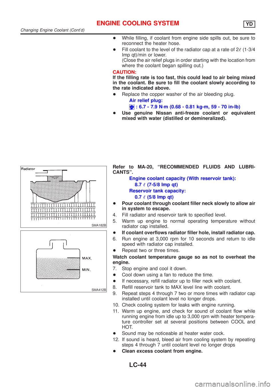
4. Fill radiator and reservoir tank to specified level.
5. Warm up engine to normal operating temperature without
radiator cap installed.
+If coolant overflows radiator filler hole, install radiator cap.
6. Run engine at 3,000 rpm for 10 seconds and return to idle
speed with radiator cap installed.
+Repeat two or three times.
Watch coolant temperature gauge so as not to overheat the
engine.
7. Stop engine and cool it down.
+Cool down using a fan to reduce the time.
+If necessary, refill radiator up to filler neck with coolant.
8. Refill reservoir tank to MAX level line with coolant.
9. Repeat steps 4 through 7 two or more times with radiator cap
installed until coolant level no longer drops.
10. Check cooling system for leaks with engine running.
11. Warm up engine, and check for sound of coolant flow while
running engine from idle up to 3,000 rpm with heater tempera-
ture controller set at several positions between COOL and
HOT.
+Sound may be noticeable at heater water cock.
12. If sound is heard, bleed air from cooling system by repeating
steps 4 through 7 until coolant level no longer drops
+Clean excess coolant from engine.
ENGINE COOLING SYSTEMYD
Changing Engine Coolant (Cont'd)
LC-44
Page 293 of 2493
Ð FLUSHING COOLING SYSTEM ÐNJLC0079S031. Open air relief plug.
2. Fill radiator with water until water spills from the air relief hole,
then close air relief plug. Fill radiator and reservoir tank with
water and reinstall radiator cap.
3. Run engine and warm it up to normal operating temperature.
4. Rev engine two or three times under no-load.
5. Stop engine and wait until it cools down.
6. Drain water.
7. Repeat steps 1 through 6 until clear water begins to drain from
radiator.
ENGINE COOLING SYSTEMYD
Changing Engine Coolant (Cont'd)
LC-45
Page 305 of 2493
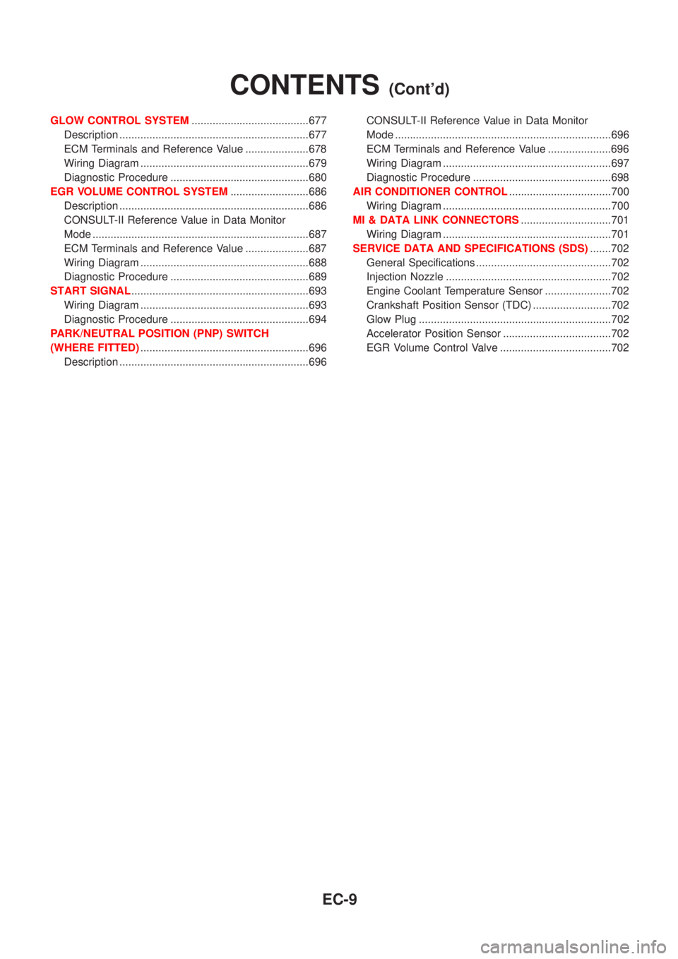
GLOW CONTROL SYSTEM.......................................677
Description ...............................................................677
ECM Terminals and Reference Value .....................678
Wiring Diagram ........................................................679
Diagnostic Procedure ..............................................680
EGR VOLUME CONTROL SYSTEM..........................686
Description ...............................................................686
CONSULT-II Reference Value in Data Monitor
Mode ........................................................................687
ECM Terminals and Reference Value .....................687
Wiring Diagram ........................................................688
Diagnostic Procedure ..............................................689
START SIGNAL...........................................................693
Wiring Diagram ........................................................693
Diagnostic Procedure ..............................................694
PARK/NEUTRAL POSITION (PNP) SWITCH
(WHERE FITTED)........................................................696
Description ...............................................................696CONSULT-II Reference Value in Data Monitor
Mode ........................................................................696
ECM Terminals and Reference Value .....................696
Wiring Diagram ........................................................697
Diagnostic Procedure ..............................................698
AIR CONDITIONER CONTROL..................................700
Wiring Diagram ........................................................700
MI & DATA LINK CONNECTORS..............................701
Wiring Diagram ........................................................701
SERVICE DATA AND SPECIFICATIONS (SDS).......702
General Specifications .............................................702
Injection Nozzle .......................................................702
Engine Coolant Temperature Sensor ......................702
Crankshaft Position Sensor (TDC) ..........................702
Glow Plug ................................................................702
Accelerator Position Sensor ....................................702
EGR Volume Control Valve .....................................702
CONTENTS(Cont'd)
EC-9
Page 335 of 2493
If results are unsatisfactory, perform Fuel Pressure Regulator
Check, EC-39.
SEF718B
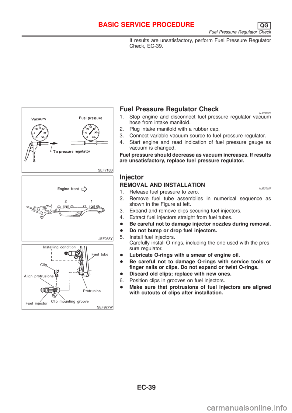
Fuel Pressure Regulator CheckNJEC00261. Stop engine and disconnect fuel pressure regulator vacuum
hose from intake manifold.
2. Plug intake manifold with a rubber cap.
3. Connect variable vacuum source to fuel pressure regulator.
4. Start engine and read indication of fuel pressure gauge as
vacuum is changed.
Fuel pressure should decrease as vacuum increases. If results
are unsatisfactory, replace fuel pressure regulator.
JEF088Y
SEF927W
Injector
REMOVAL AND INSTALLATIONNJEC00271. Release fuel pressure to zero.
2. Remove fuel tube assemblies in numerical sequence as
shown in the Figure at left.
3. Expand and remove clips securing fuel injectors.
4. Extract fuel injectors straight from fuel tubes.
+Be careful not to damage injector nozzles during removal.
+Do not bump or drop fuel injectors.
5. Install fuel injectors.
Carefully install O-rings, including the one used with the pres-
sure regulator.
+Lubricate O-rings with a smear of engine oil.
+Be careful not to damage O-rings with service tools or
finger nails or clips. Do not expand or twist O-rings.
+Discard old clips; replace with new ones.
6. Position clips in grooves on fuel injectors.
+Make sure that protrusions of fuel injectors are aligned
with cutouts of clips after installation.
BASIC SERVICE PROCEDUREQG
Fuel Pressure Regulator Check
EC-39
Page 338 of 2493

SEF933W
SEF284G
+Method B
a) Remove No. 1 ignition coil.
b) Connect No. 1 ignition coil and No. 1 spark plug with suitable
high-tension wire as shown, and attach timing light clamp to
this wire.
c) Check ignition timing.
SEF166Y
PreparationNJEC0592+Make sure that the following parts are in good order.
a)Battery
b)Ignition system
c)Engine oil and coolant levels
d)Fuses
e)ECM harness connector
f)Vacuum hoses
g)Air intake system
(Oil filler cap, oil level gauge, etc.)
BASIC SERVICE PROCEDUREQG
How to Check Idle Speed and Ignition Timing (Cont'd)
EC-42
Page 385 of 2493
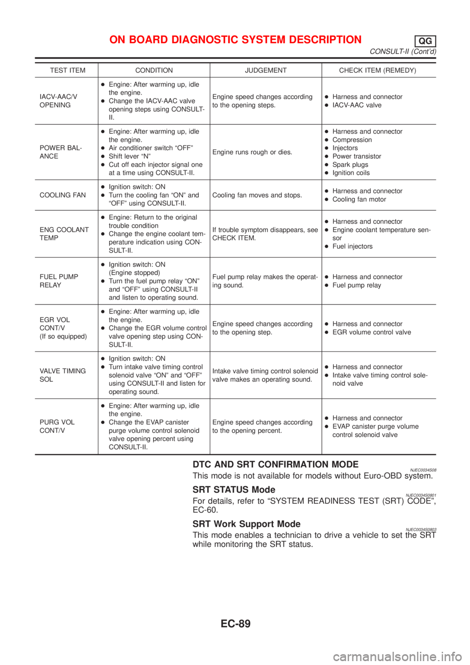
TEST ITEM CONDITION JUDGEMENT CHECK ITEM (REMEDY)
IACV-AAC/V
OPENING+Engine: After warming up, idle
the engine.
+Change the IACV-AAC valve
opening steps using CONSULT-
II.Engine speed changes according
to the opening steps.+Harness and connector
+IACV-AAC valve
POWER BAL-
ANCE+Engine: After warming up, idle
the engine.
+Air conditioner switch ªOFFº
+Shift lever ªNº
+Cut off each injector signal one
at a time using CONSULT-II.Engine runs rough or dies.+Harness and connector
+Compression
+Injectors
+Power transistor
+Spark plugs
+Ignition coils
COOLING FAN+Ignition switch: ON
+Turn the cooling fan ªONº and
ªOFFº using CONSULT-II.Cooling fan moves and stops.+Harness and connector
+Cooling fan motor
ENG COOLANT
TEMP+Engine: Return to the original
trouble condition
+Change the engine coolant tem-
perature indication using CON-
SULT-II.If trouble symptom disappears, see
CHECK ITEM.+Harness and connector
+Engine coolant temperature sen-
sor
+Fuel injectors
FUEL PUMP
RELAY+Ignition switch: ON
(Engine stopped)
+Turn the fuel pump relay ªONº
and ªOFFº using CONSULT-II
and listen to operating sound.Fuel pump relay makes the operat-
ing sound.+Harness and connector
+Fuel pump relay
EGR VOL
CONT/V
(If so equipped)+Engine: After warming up, idle
the engine.
+Change the EGR volume control
valve opening step using CON-
SULT-II.Engine speed changes according
to the opening step.+Harness and connector
+EGR volume control valve
VALVE TIMING
SOL+Ignition switch: ON
+Turn intake valve timing control
solenoid valve ªONº and ªOFFº
using CONSULT-II and listen for
operating sound.Intake valve timing control solenoid
valve makes an operating sound.+Harness and connector
+Intake valve timing control sole-
noid valve
PURG VOL
CONT/V+Engine: After warming up, idle
the engine.
+Change the EVAP canister
purge volume control solenoid
valve opening percent using
CONSULT-II.Engine speed changes according
to the opening percent.+Harness and connector
+EVAP canister purge volume
control solenoid valve
DTC AND SRT CONFIRMATION MODENJEC0034S08This mode is not available for models without Euro-OBD system.
SRT STATUS ModeNJEC0034S0801For details, refer to ªSYSTEM READINESS TEST (SRT) CODEº,
EC-60.
SRT Work Support ModeNJEC0034S0803This mode enables a technician to drive a vehicle to set the SRT
while monitoring the SRT status.
ON BOARD DIAGNOSTIC SYSTEM DESCRIPTIONQG
CONSULT-II (Cont'd)
EC-89
Page 390 of 2493
MEF036D
SEF233G
SEF234G
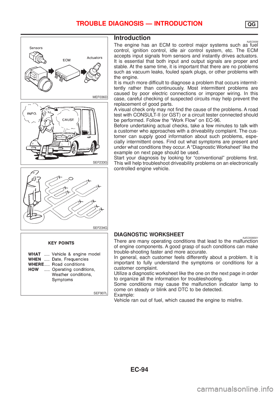
IntroductionNJEC0036The engine has an ECM to control major systems such as fuel
control, ignition control, idle air control system, etc. The ECM
accepts input signals from sensors and instantly drives actuators.
It is essential that both input and output signals are proper and
stable. At the same time, it is important that there are no problems
such as vacuum leaks, fouled spark plugs, or other problems with
the engine.
It is much more difficult to diagnose a problem that occurs intermit-
tently rather than continuously. Most intermittent problems are
caused by poor electric connections or improper wiring. In this
case, careful checking of suspected circuits may help prevent the
replacement of good parts.
A visual check only may not find the cause of the problems. A road
test with CONSULT-II (or GST) or a circuit tester connected should
be performed. Follow the ªWork Flowº on EC-96.
Before undertaking actual checks, take a few minutes to talk with
a customer who approaches with a driveability complaint. The cus-
tomer can supply good information about such problems, espe-
cially intermittent ones. Find out what symptoms are present and
under what conditions they occur. A ªDiagnostic Worksheetº like the
example on next page should be used.
Start your diagnosis by looking for ªconventionalº problems first.
This will help troubleshoot driveability problems on an electronically
controlled engine vehicle.
SEF907L
DIAGNOSTIC WORKSHEETNJEC0036S01There are many operating conditions that lead to the malfunction
of engine components. A good grasp of such conditions can make
trouble-shooting faster and more accurate.
In general, each customer feels differently about a problem. It is
important to fully understand the symptoms or conditions for a
customer complaint.
Utilize a diagnostic worksheet like the one on the next page in order
to organize all the information for troubleshooting.
Some conditions may cause the malfunction indicator lamp to
come on steady or blink and DTC to be detected.
Example:
Vehicle ran out of fuel, which caused the engine to misfire.
TROUBLE DIAGNOSIS Ð INTRODUCTIONQG
EC-94