suspension NISSAN ALMERA N16 2001 Electronic Owner's Guide
[x] Cancel search | Manufacturer: NISSAN, Model Year: 2001, Model line: ALMERA N16, Model: NISSAN ALMERA N16 2001Pages: 2493, PDF Size: 66.97 MB
Page 1692 of 2493
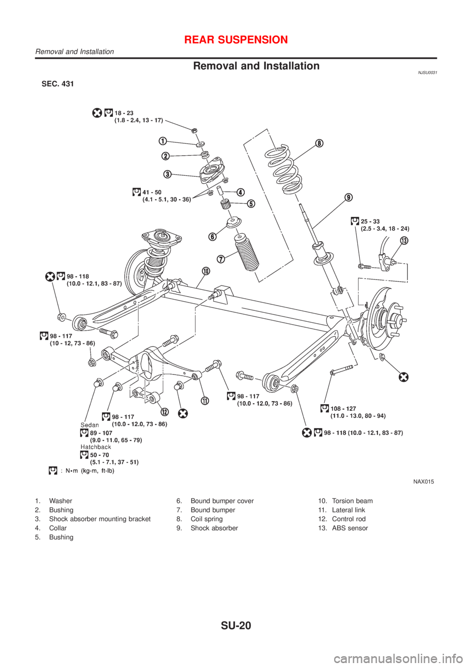
Removal and InstallationNJSU0031
NAX015
1. Washer
2. Bushing
3. Shock absorber mounting bracket
4. Collar
5. Bushing6. Bound bumper cover
7. Bound bumper
8. Coil spring
9. Shock absorber10. Torsion beam
11. Lateral link
12. Control rod
13. ABS sensor
REAR SUSPENSION
Removal and Installation
SU-20
Page 1693 of 2493
SRA695A
SSU038
REMOVALNJSU0031S01CAUTION:
+Before removing the rear suspension assembly, discon-
nect the ABS wheel sensor from the assembly. Failure to
do so may result in damage to the sensor wires and the
sensor becoming inoperative.
+Remove suspension assembly.
1. Disconnect brake hydraulic lines and parking brake cable at
toggle lever. (Models with drum brakes.)
+Drain brake fluid before disconnecting brake lines.
2. Disconnect parking brake cable from caliper and remove brake
caliper and rotor. (Models with disc brakes.)
Suspend caliper assembly with wire so as not to stretch
brake hose.
Be careful not to depress brake pedal, or piston will pop
out.
Make sure brake hose is not twisted.
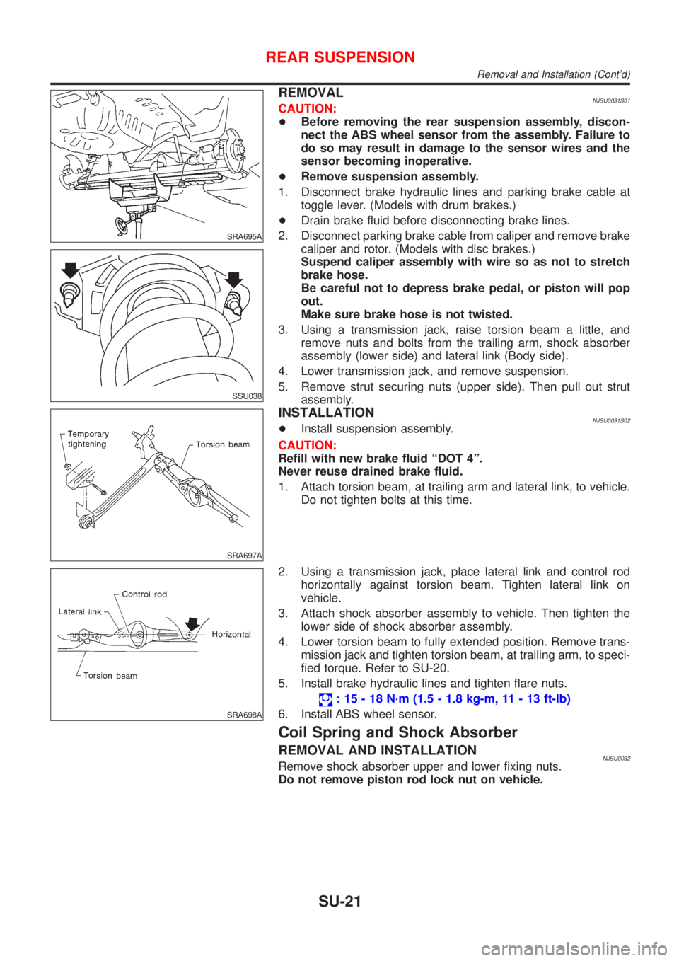
3. Using a transmission jack, raise torsion beam a little, and
remove nuts and bolts from the trailing arm, shock absorber
assembly (lower side) and lateral link (Body side).
4. Lower transmission jack, and remove suspension.
5. Remove strut securing nuts (upper side). Then pull out strut
assembly.
SRA697A
INSTALLATIONNJSU0031S02+Install suspension assembly.
CAUTION:
Refill with new brake fluid ªDOT 4º.
Never reuse drained brake fluid.
1. Attach torsion beam, at trailing arm and lateral link, to vehicle.
Do not tighten bolts at this time.
SRA698A
2. Using a transmission jack, place lateral link and control rod
horizontally against torsion beam. Tighten lateral link on
vehicle.
3. Attach shock absorber assembly to vehicle. Then tighten the
lower side of shock absorber assembly.
4. Lower torsion beam to fully extended position. Remove trans-
mission jack and tighten torsion beam, at trailing arm, to speci-
fied torque. Refer to SU-20.
5. Install brake hydraulic lines and tighten flare nuts.
: 15 - 18 N´m (1.5 - 1.8 kg-m, 11 - 13 ft-lb)
6. Install ABS wheel sensor.
Coil Spring and Shock Absorber
REMOVAL AND INSTALLATIONNJSU0032Remove shock absorber upper and lower fixing nuts.
Do not remove piston rod lock nut on vehicle.
REAR SUSPENSION
Removal and Installation (Cont'd)
SU-21
Page 1694 of 2493
SRA806A
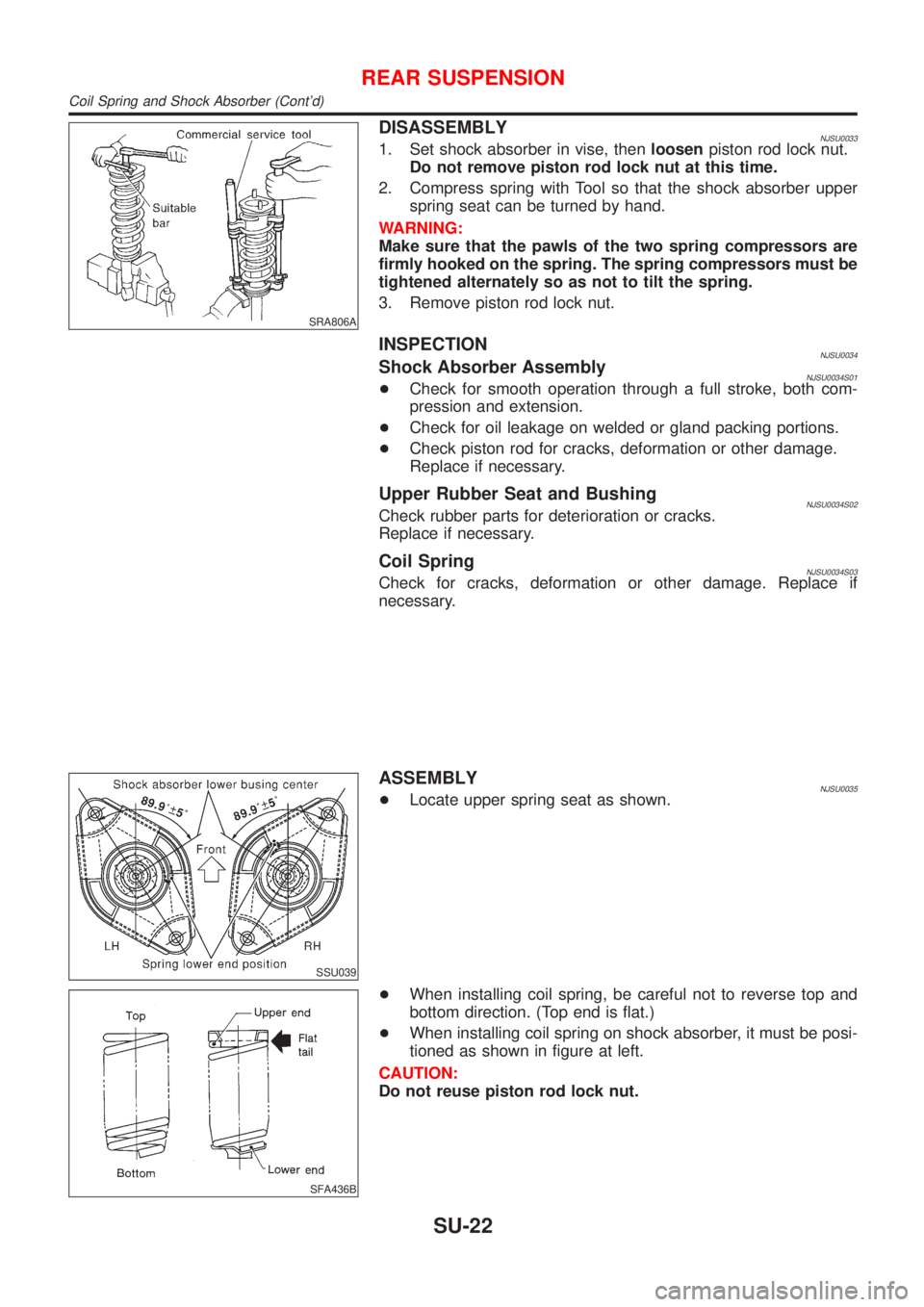
DISASSEMBLYNJSU00331. Set shock absorber in vise, thenloosenpiston rod lock nut.
Do not remove piston rod lock nut at this time.
2. Compress spring with Tool so that the shock absorber upper
spring seat can be turned by hand.
WARNING:
Make sure that the pawls of the two spring compressors are
firmly hooked on the spring. The spring compressors must be
tightened alternately so as not to tilt the spring.
3. Remove piston rod lock nut.
INSPECTIONNJSU0034Shock Absorber AssemblyNJSU0034S01+Check for smooth operation through a full stroke, both com-
pression and extension.
+Check for oil leakage on welded or gland packing portions.
+Check piston rod for cracks, deformation or other damage.
Replace if necessary.
Upper Rubber Seat and BushingNJSU0034S02Check rubber parts for deterioration or cracks.
Replace if necessary.
Coil SpringNJSU0034S03Check for cracks, deformation or other damage. Replace if
necessary.
SSU039
ASSEMBLYNJSU0035+Locate upper spring seat as shown.
SFA436B
+When installing coil spring, be careful not to reverse top and
bottom direction. (Top end is flat.)
+When installing coil spring on shock absorber, it must be posi-
tioned as shown in figure at left.
CAUTION:
Do not reuse piston rod lock nut.
REAR SUSPENSION
Coil Spring and Shock Absorber (Cont'd)
SU-22
Page 1695 of 2493
Torsion Beam, Lateral Link and Control Rod
DISASSEMBLYNJSU0036+Remove torsion beam assembly. Refer to ªRemoval and
Installationº, ªREAR SUSPENSIONº, SU-21.
+Remove lateral link and control rod from torsion beam.
ARA072
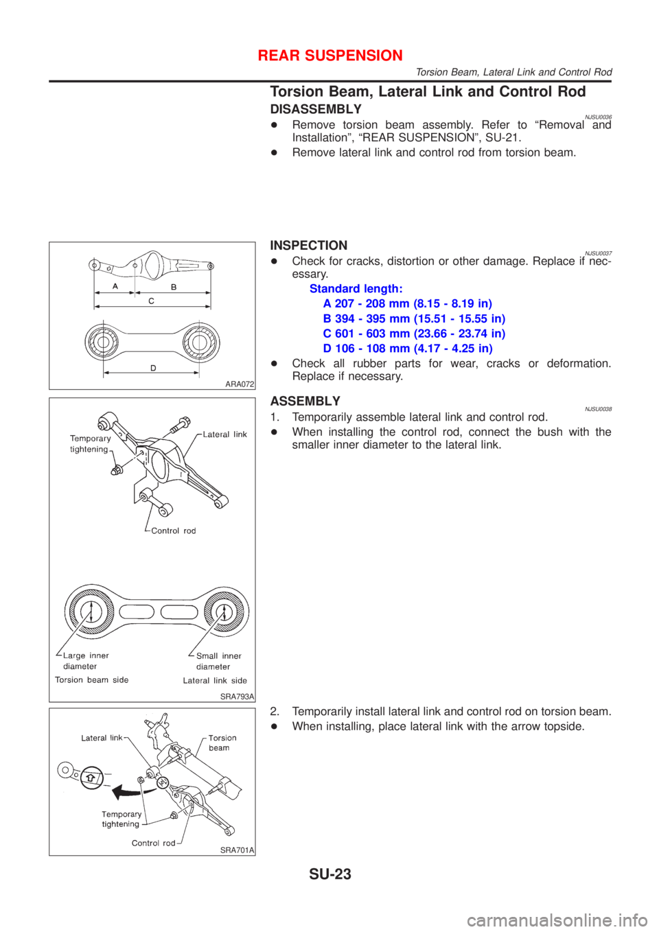
INSPECTIONNJSU0037+Check for cracks, distortion or other damage. Replace if nec-
essary.
Standard length:
A 207 - 208 mm (8.15 - 8.19 in)
B 394 - 395 mm (15.51 - 15.55 in)
C 601 - 603 mm (23.66 - 23.74 in)
D 106 - 108 mm (4.17 - 4.25 in)
+Check all rubber parts for wear, cracks or deformation.
Replace if necessary.
SRA793A
ASSEMBLYNJSU00381. Temporarily assemble lateral link and control rod.
+When installing the control rod, connect the bush with the
smaller inner diameter to the lateral link.
SRA701A
2. Temporarily install lateral link and control rod on torsion beam.
+When installing, place lateral link with the arrow topside.
REAR SUSPENSION
Torsion Beam, Lateral Link and Control Rod
SU-23
Page 1696 of 2493
SRA702A
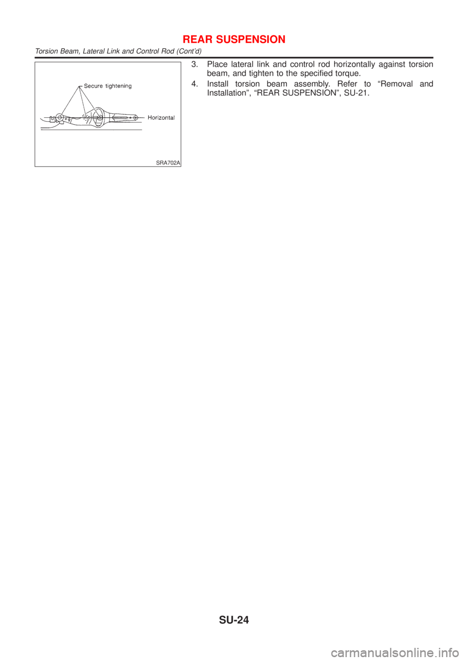
3. Place lateral link and control rod horizontally against torsion
beam, and tighten to the specified torque.
4. Install torsion beam assembly. Refer to ªRemoval and
Installationº, ªREAR SUSPENSIONº, SU-21.
REAR SUSPENSION
Torsion Beam, Lateral Link and Control Rod (Cont'd)
SU-24
Page 1697 of 2493
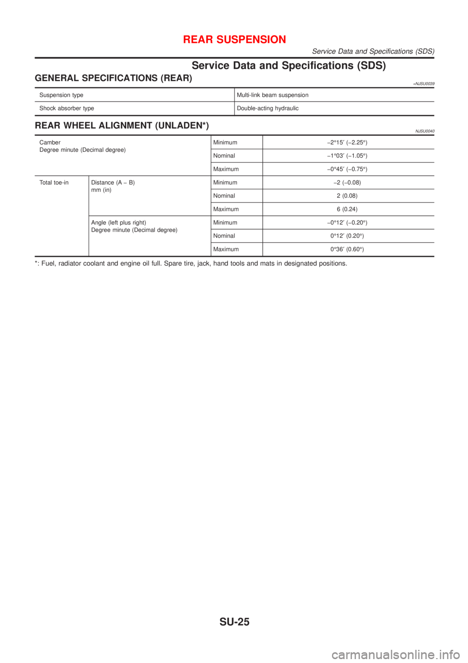
Service Data and Specifications (SDS)
GENERAL SPECIFICATIONS (REAR)=NJSU0039
Suspension type Multi-link beam suspension
Shock absorber type Double-acting hydraulic
REAR WHEEL ALIGNMENT (UNLADEN*)NJSU0040
Camber
Degree minute (Decimal degree)Minimum þ2É15¢(þ2.25É)
Nominal þ1É03¢(þ1.05É)
Maximum þ0É45¢(þ0.75É)
Total toe-in Distance (A þ B)
mm (in)Minimum þ2 (þ0.08)
Nominal 2 (0.08)
Maximum 6 (0.24)
Angle (left plus right)
Degree minute (Decimal degree)Minimum þ0É12¢(þ0.20É)
Nominal 0É12¢(0.20É)
Maximum 0É36¢(0.60É)
*: Fuel, radiator coolant and engine oil full. Spare tire, jack, hand tools and mats in designated positions.
REAR SUSPENSION
Service Data and Specifications (SDS)
SU-25
Page 1698 of 2493

REAR SUSPENSION
Service Data and Specifications (SDS) (Cont'd)
SU-26
Page 1704 of 2493
NJBR0005
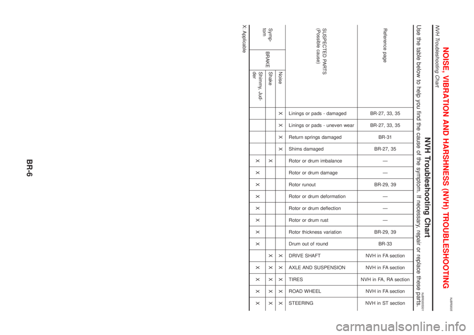
NVH Troubleshooting ChartNJBR0005S01Use the table below to help you find the cause of the symptom. If necessary, repair or replace these parts.
Reference page
BR-27, 33, 35
BR-27, 33, 35
BR-31
BR-27, 35
Ð
Ð
BR-29, 39
Ð
Ð
Ð
BR-29, 39
BR-33
NVH in FA section
NVH in FA section
NVH in FA, RA section
NVH in FA section
NVH in ST section
SUSPECTED PARTS
(Possible cause)
Linings or pads - damaged
Linings or pads - uneven wear
Return springs damaged
Shims damaged
Rotor or drum imbalance
Rotor or drum damage
Rotor runout
Rotor or drum deformation
Rotor or drum deflection
Rotor or drum rust
Rotor thickness variation
Drum out of round
DRIVE SHAFT
AXLE AND SUSPENSION
TIRES
ROAD WHEEL
STEERING
Symp-
tomBRAKENoiseXXXX XXXXX
Shake XXXXXX
Shimmy, Jud-
derXXXXXXXX XXXX
X: Applicable
NOISE, VIBRATION AND HARSHNESS (NVH) TROUBLESHOOTING
NVH Troubleshooting Chart
BR-6
Page 1795 of 2493
NJST0006
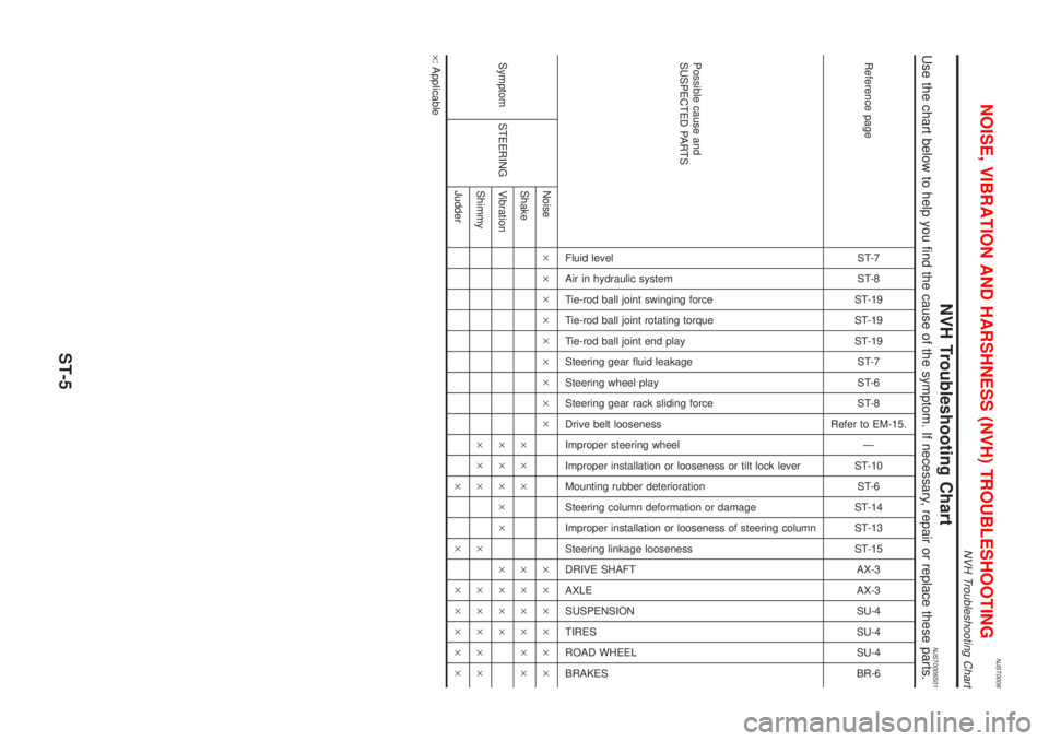
NVH Troubleshooting ChartNJST0006S01Use the chart below to help you find the cause of the symptom. If necessary, repair or replace these parts.
Reference pageST-7
ST-8
ST-19
ST-19
ST-19
ST-7
ST-6
ST-8
Refer to EM-15.
Ð
ST-10
ST-6
ST-14
ST-13
ST-15
AX-3
AX-3
SU-4
SU-4
SU-4
BR-6
Possible cause and
SUSPECTED PARTS
Fluid level
Air in hydraulic system
Tie-rod ball joint swinging force
Tie-rod ball joint rotating torque
Tie-rod ball joint end play
Steering gear fluid leakage
Steering wheel play
Steering gear rack sliding force
Drive belt looseness
Improper steering wheel
Improper installation or looseness or tilt lock lever
Mounting rubber deterioration
Steering column deformation or damage
Improper installation or looseness of steering column
Steering linkage looseness
DRIVE SHAFT
AXLE
SUSPENSION
TIRES
ROAD WHEEL
BRAKES
Symptom STEERINGNoise´´´´´´´´´ ´´´´´´
Shake´´´ ´´´´´´
Vibration´´´´´ ´´´´
Shimmy´´´ ´ ´´´´´
Judder´ ´ ´´´´´
´: Applicable
NOISE, VIBRATION AND HARSHNESS (NVH) TROUBLESHOOTING
NVH Troubleshooting Chart
ST-5
Page 1796 of 2493
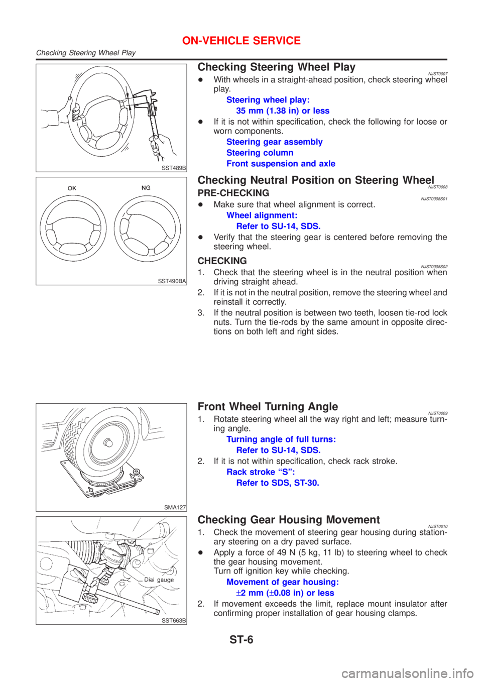
SST489B
Checking Steering Wheel PlayNJST0007+With wheels in a straight-ahead position, check steering wheel
play.
Steering wheel play:
35 mm (1.38 in) or less
+If it is not within specification, check the following for loose or
worn components.
Steering gear assembly
Steering column
Front suspension and axle
SST490BA
Checking Neutral Position on Steering WheelNJST0008PRE-CHECKINGNJST0008S01+Make sure that wheel alignment is correct.
Wheel alignment:
Refer to SU-14, SDS.
+Verify that the steering gear is centered before removing the
steering wheel.
CHECKINGNJST0008S021. Check that the steering wheel is in the neutral position when
driving straight ahead.
2. If it is not in the neutral position, remove the steering wheel and
reinstall it correctly.
3. If the neutral position is between two teeth, loosen tie-rod lock
nuts. Turn the tie-rods by the same amount in opposite direc-
tions on both left and right sides.
SMA127
Front Wheel Turning AngleNJST00091. Rotate steering wheel all the way right and left; measure turn-
ing angle.
Turning angle of full turns:
Refer to SU-14, SDS.
2. If it is not within specification, check rack stroke.
Rack stroke ªSº:
Refer to SDS, ST-30.
SST663B
Checking Gear Housing MovementNJST00101. Check the movement of steering gear housing during station-
ary steering on a dry paved surface.
+Apply a force of 49 N (5 kg, 11 lb) to steering wheel to check
the gear housing movement.
Turn off ignition key while checking.
Movement of gear housing:
±2mm(±0.08 in) or less
2. If movement exceeds the limit, replace mount insulator after
confirming proper installation of gear housing clamps.
ON-VEHICLE SERVICE
Checking Steering Wheel Play
ST-6