NISSAN ALMERA N16 2001 Electronic Repair Manual
Manufacturer: NISSAN, Model Year: 2001, Model line: ALMERA N16, Model: NISSAN ALMERA N16 2001Pages: 2493, PDF Size: 66.97 MB
Page 571 of 2493
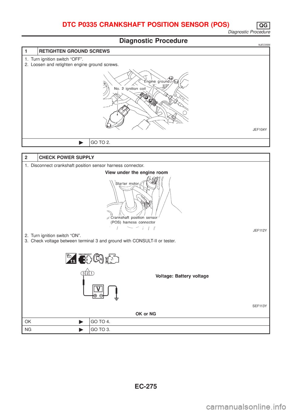
Diagnostic ProcedureNJEC0556
1 RETIGHTEN GROUND SCREWS
1. Turn ignition switch ªOFFº.
2. Loosen and retighten engine ground screws.
JEF104Y
©GO TO 2.
2 CHECK POWER SUPPLY
1. Disconnect crankshaft position sensor harness connector.
JEF112Y
2. Turn ignition switch ªONº.
3. Check voltage between terminal 3 and ground with CONSULT-II or tester.
SEF113Y
OK or NG
OK©GO TO 4.
NG©GO TO 3.
DTC P0335 CRANKSHAFT POSITION SENSOR (POS)QG
Diagnostic Procedure
EC-275
Page 572 of 2493
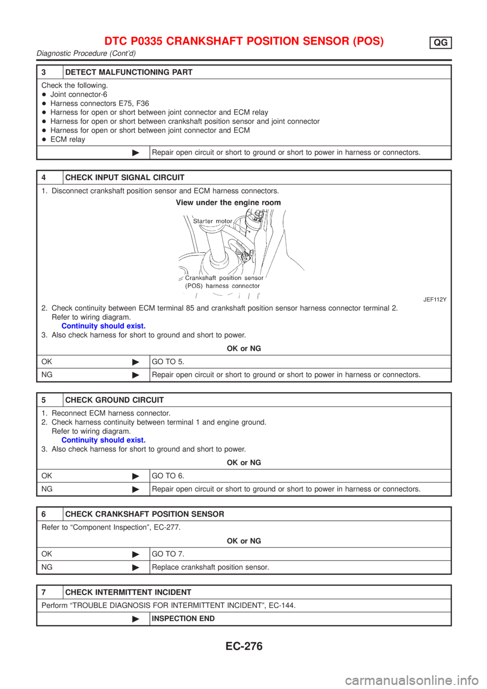
3 DETECT MALFUNCTIONING PART
Check the following.
+Joint connector-6
+Harness connectors E75, F36
+Harness for open or short between joint connector and ECM relay
+Harness for open or short between crankshaft position sensor and joint connector
+Harness for open or short between joint connector and ECM
+ECM relay
©Repair open circuit or short to ground or short to power in harness or connectors.
4 CHECK INPUT SIGNAL CIRCUIT
1. Disconnect crankshaft position sensor and ECM harness connectors.
JEF112Y
2. Check continuity between ECM terminal 85 and crankshaft position sensor harness connector terminal 2.
Refer to wiring diagram.
Continuity should exist.
3. Also check harness for short to ground and short to power.
OK or NG
OK©GO TO 5.
NG©Repair open circuit or short to ground or short to power in harness or connectors.
5 CHECK GROUND CIRCUIT
1. Reconnect ECM harness connector.
2. Check harness continuity between terminal 1 and engine ground.
Refer to wiring diagram.
Continuity should exist.
3. Also check harness for short to ground and short to power.
OK or NG
OK©GO TO 6.
NG©Repair open circuit or short to ground or short to power in harness or connectors.
6 CHECK CRANKSHAFT POSITION SENSOR
Refer to ªComponent Inspectionº, EC-277.
OK or NG
OK©GO TO 7.
NG©Replace crankshaft position sensor.
7 CHECK INTERMITTENT INCIDENT
Perform ªTROUBLE DIAGNOSIS FOR INTERMITTENT INCIDENTº, EC-144.
©INSPECTION END
DTC P0335 CRANKSHAFT POSITION SENSOR (POS)QG
Diagnostic Procedure (Cont'd)
EC-276
Page 573 of 2493
SEF121X
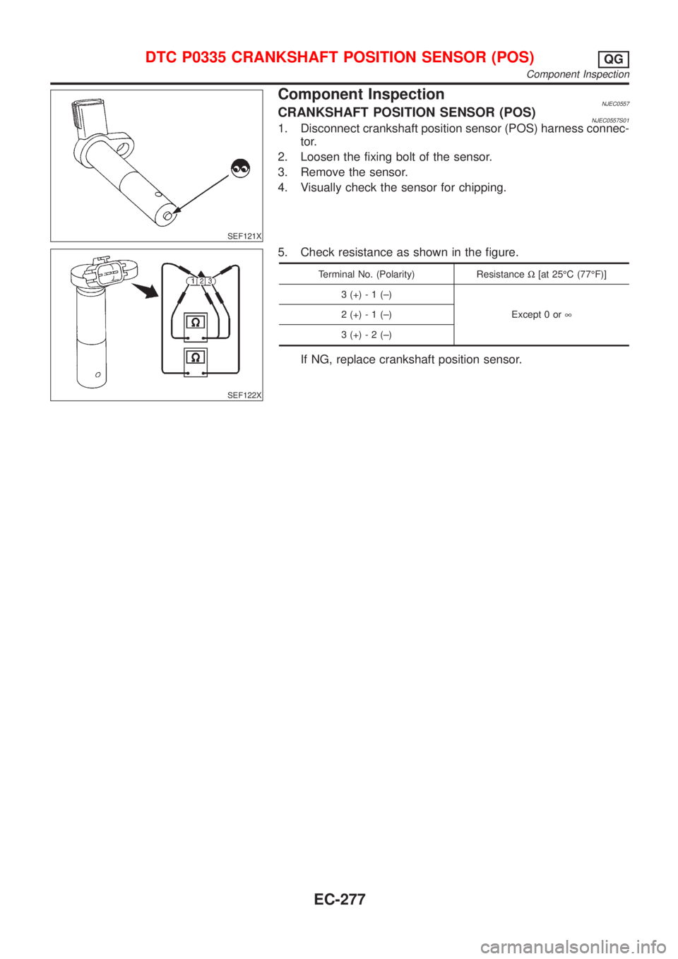
Component InspectionNJEC0557CRANKSHAFT POSITION SENSOR (POS)NJEC0557S011. Disconnect crankshaft position sensor (POS) harness connec-
tor.
2. Loosen the fixing bolt of the sensor.
3. Remove the sensor.
4. Visually check the sensor for chipping.
SEF122X
5. Check resistance as shown in the figure.
Terminal No. (Polarity) ResistanceW[at 25ÉC (77ÉF)]
3 (+) - 1 (±)
Except 0 or¥ 2 (+) - 1 (±)
3 (+) - 2 (±)
If NG, replace crankshaft position sensor.
DTC P0335 CRANKSHAFT POSITION SENSOR (POS)QG
Component Inspection
EC-277
Page 574 of 2493
SEF058X
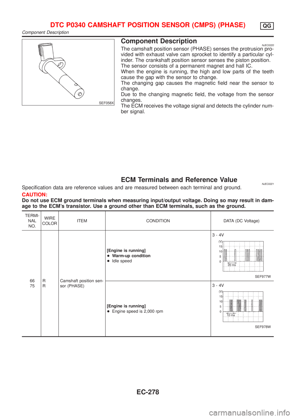
Component DescriptionNJEC0220The camshaft position sensor (PHASE) senses the protrusion pro-
vided with exhaust valve cam sprocket to identify a particular cyl-
inder. The crankshaft position sensor senses the piston position.
The sensor consists of a permanent magnet and hall IC.
When the engine is running, the high and low parts of the teeth
cause the gap with the sensor to change.
The changing gap causes the magnetic field near the sensor to
change.
Due to the changing magnetic field, the voltage from the sensor
changes.
The ECM receives the voltage signal and detects the cylinder num-
ber signal.
ECM Terminals and Reference ValueNJEC0221Specification data are reference values and are measured between each terminal and ground.
CAUTION:
Do not use ECM ground terminals when measuring input/output voltage. Doing so may result in dam-
age to the ECM's transistor. Use a ground other than ECM terminals, such as the ground.
TERMI-
NAL
NO.WIRE
COLORITEM CONDITION DATA (DC Voltage)
66
75R
RCamshaft position sen-
sor (PHASE)[Engine is running]
+Warm-up condition
+Idle speed3-4V
SEF977W
[Engine is running]
+Engine speed is 2,000 rpm3-4V
SEF978W
DTC P0340 CAMSHAFT POSITION SENSOR (CMPS) (PHASE)QG
Component Description
EC-278
Page 575 of 2493
On Board Diagnosis LogicNJEC0222
DTC No. Malfunction is detected when ... Check Items (Possible Cause)
P0340
0340+The cylinder No. signal is not entered to ECM for the first
few seconds during engine cranking.
+The cylinder No. signal is not entered to ECM during
engine running.
+The cylinder No. signal is not in the normal pattern dur-
ing engine running.+Harness or connectors
(The camshaft position sensor (PHASE) circuit is
open or shorted.)
+Camshaft position sensor (PHASE)
+Starter motor (Refer to EL section.)
+Starting system circuit (Refer to EL section.)
DTC Confirmation ProcedureNJEC0223NOTE:
If ªDTC Confirmation Procedureº has been previously conducted,
always turn ignition switch ªOFFº and wait at least 9 seconds
before conducting the next test.
TESTING CONDITION:
Before performing the following procedure, confirm that bat-
tery voltage is more than 10.5V.
SEF013Y
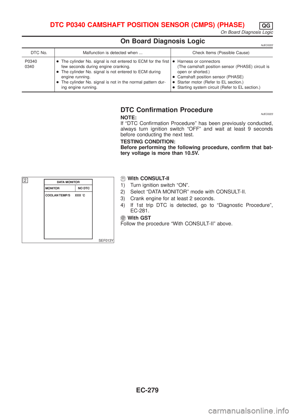
With CONSULT-II
1) Turn ignition switch ªONº.
2) Select ªDATA MONITORº mode with CONSULT-II.
3) Crank engine for at least 2 seconds.
4) If 1st trip DTC is detected, go to ªDiagnostic Procedureº,
EC-281.
With GST
Follow the procedure ªWith CONSULT-IIº above.
DTC P0340 CAMSHAFT POSITION SENSOR (CMPS) (PHASE)QG
On Board Diagnosis Logic
EC-279
Page 576 of 2493
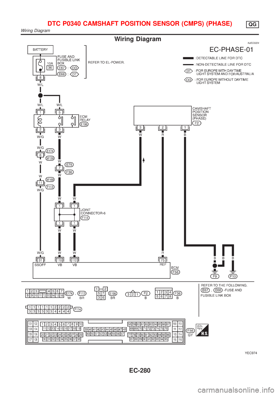
Wiring DiagramNJEC0224
YEC974
DTC P0340 CAMSHAFT POSITION SENSOR (CMPS) (PHASE)QG
Wiring Diagram
EC-280
Page 577 of 2493
Diagnostic ProcedureNJEC0225
1 CHECK STARTING SYSTEM
Does the engine turn over?
(Does the starter motor operate?)
YesorNo
Ye s©GO TO 2.
No©Check starting system. (Refer to EL section.)
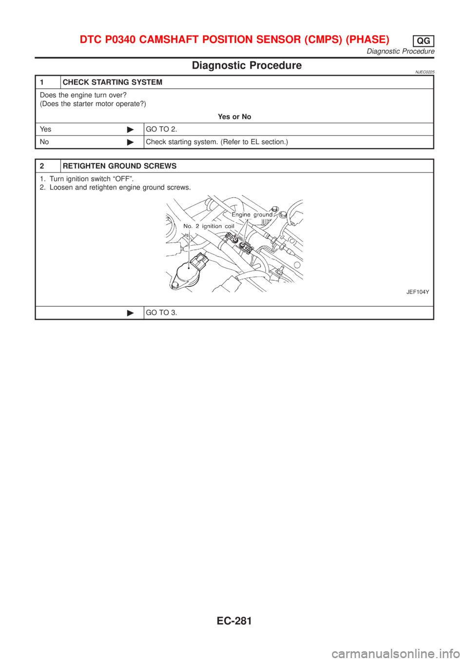
2 RETIGHTEN GROUND SCREWS
1. Turn ignition switch ªOFFº.
2. Loosen and retighten engine ground screws.
JEF104Y
©GO TO 3.
DTC P0340 CAMSHAFT POSITION SENSOR (CMPS) (PHASE)QG
Diagnostic Procedure
EC-281
Page 578 of 2493
3 CHECK POWER SUPPLY
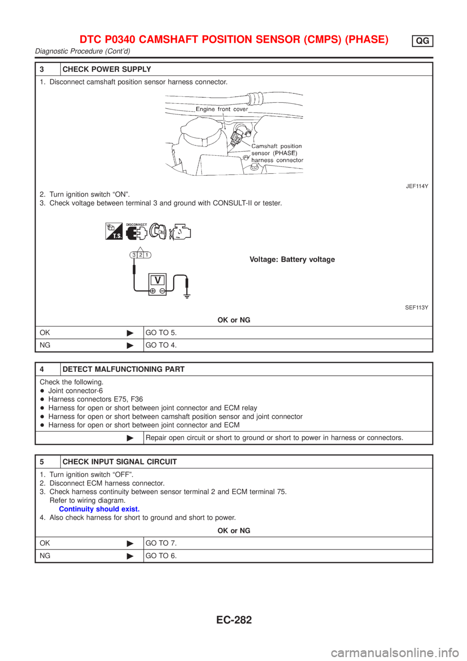
1. Disconnect camshaft position sensor harness connector.
JEF114Y
2. Turn ignition switch ªONº.
3. Check voltage between terminal 3 and ground with CONSULT-II or tester.
SEF113Y
OK or NG
OK©GO TO 5.
NG©GO TO 4.
4 DETECT MALFUNCTIONING PART
Check the following.
+Joint connector-6
+Harness connectors E75, F36
+Harness for open or short between joint connector and ECM relay
+Harness for open or short between camshaft position sensor and joint connector
+Harness for open or short between joint connector and ECM
©Repair open circuit or short to ground or short to power in harness or connectors.
5 CHECK INPUT SIGNAL CIRCUIT
1. Turn ignition switch ªOFFº.
2. Disconnect ECM harness connector.
3. Check harness continuity between sensor terminal 2 and ECM terminal 75.
Refer to wiring diagram.
Continuity should exist.
4. Also check harness for short to ground and short to power.
OK or NG
OK©GO TO 7.
NG©GO TO 6.
DTC P0340 CAMSHAFT POSITION SENSOR (CMPS) (PHASE)QG
Diagnostic Procedure (Cont'd)
EC-282
Page 579 of 2493
6 DETECT MALFUNCTIONING PART
Check the following.
+Harness for open or short between ECM and joint connector
+Harness for open or short between joint connector and camshaft position sensor
©Repair open circuit or short to ground or short to power in harness or connectors.
7 CHECK GROUND CIRCUIT
1. Turn ignition switch ªOFFº.
2. Check harness continuity between sensor terminal 1 and engine ground.
Refer to wiring diagram.
Continuity should exist.
3. Also check harness for short to ground and short to power.
OK or NG
OK©GO TO 8.
NG©Repair open circuit or short to ground or short to power in harness or connectors.
8 CHECK CAMSHAFT POSITION SENSOR
Refer to ªComponent Inspectionº, EC-284.
OK or NG
OK©GO TO 9.
NG©Replace camshaft position sensor.
9 CHECK INTERMITTENT INCIDENT
Perform ªTROUBLE DIAGNOSIS FOR INTERMITTENT INCIDENTº, EC-144.
©INSPECTION END
DTC P0340 CAMSHAFT POSITION SENSOR (CMPS) (PHASE)QG
Diagnostic Procedure (Cont'd)
EC-283
Page 580 of 2493
SEF122X
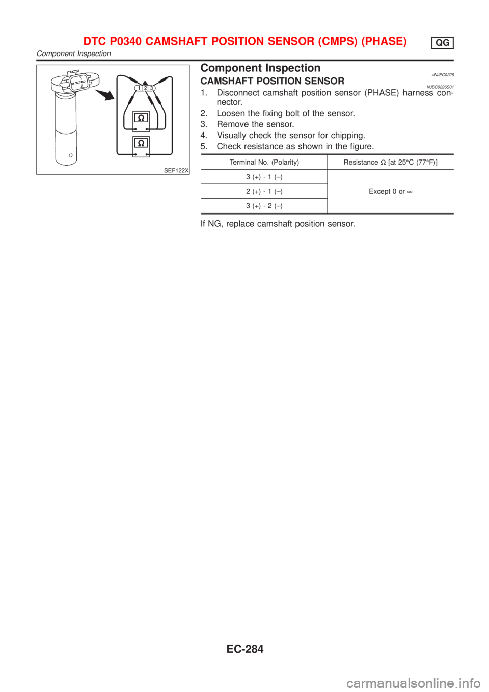
Component Inspection=NJEC0226CAMSHAFT POSITION SENSORNJEC0226S011. Disconnect camshaft position sensor (PHASE) harness con-
nector.
2. Loosen the fixing bolt of the sensor.
3. Remove the sensor.
4. Visually check the sensor for chipping.
5. Check resistance as shown in the figure.
Terminal No. (Polarity) ResistanceW[at 25ÉC (77ÉF)]
3 (+) - 1 (±)
Except 0 or¥ 2 (+) - 1 (±)
3 (+) - 2 (±)
If NG, replace camshaft position sensor.
DTC P0340 CAMSHAFT POSITION SENSOR (CMPS) (PHASE)QG
Component Inspection
EC-284