Combination meter NISSAN ALMERA N16 2001 Electronic Repair Manual
[x] Cancel search | Manufacturer: NISSAN, Model Year: 2001, Model line: ALMERA N16, Model: NISSAN ALMERA N16 2001Pages: 2493, PDF Size: 66.97 MB
Page 608 of 2493
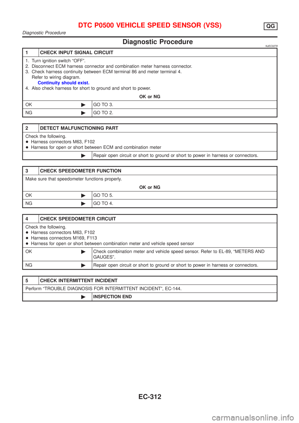
Diagnostic ProcedureNJEC0278
1 CHECK INPUT SIGNAL CIRCUIT
1. Turn ignition switch ªOFFº.
2. Disconnect ECM harness connector and combination meter harness connector.
3. Check harness continuity between ECM terminal 86 and meter terminal 4.
Refer to wiring diagram.
Continuity should exist.
4. Also check harness for short to ground and short to power.
OK or NG
OK©GO TO 3.
NG©GO TO 2.
2 DETECT MALFUNCTIONING PART
Check the following.
+Harness connectors M63, F102
+Harness for open or short between ECM and combination meter
©Repair open circuit or short to ground or short to power in harness or connectors.
3 CHECK SPEEDOMETER FUNCTION
Make sure that speedometer functions properly.
OK or NG
OK©GO TO 5.
NG©GO TO 4.
4 CHECK SPEEDOMETER CIRCUIT
Check the following.
+Harness connectors M63, F102
+Harness connectors M169, F113
+Harness for open or short between combination meter and vehicle speed sensor
OK©Check combination meter and vehicle speed sensor. Refer to EL-89, ªMETERS AND
GAUGESº.
NG©Repair open circuit or short to ground or short to power in harness or connectors.
5 CHECK INTERMITTENT INCIDENT
Perform ªTROUBLE DIAGNOSIS FOR INTERMITTENT INCIDENTº, EC-144.
©INSPECTION END
DTC P0500 VEHICLE SPEED SENSOR (VSS)QG
Diagnostic Procedure
EC-312
Page 892 of 2493
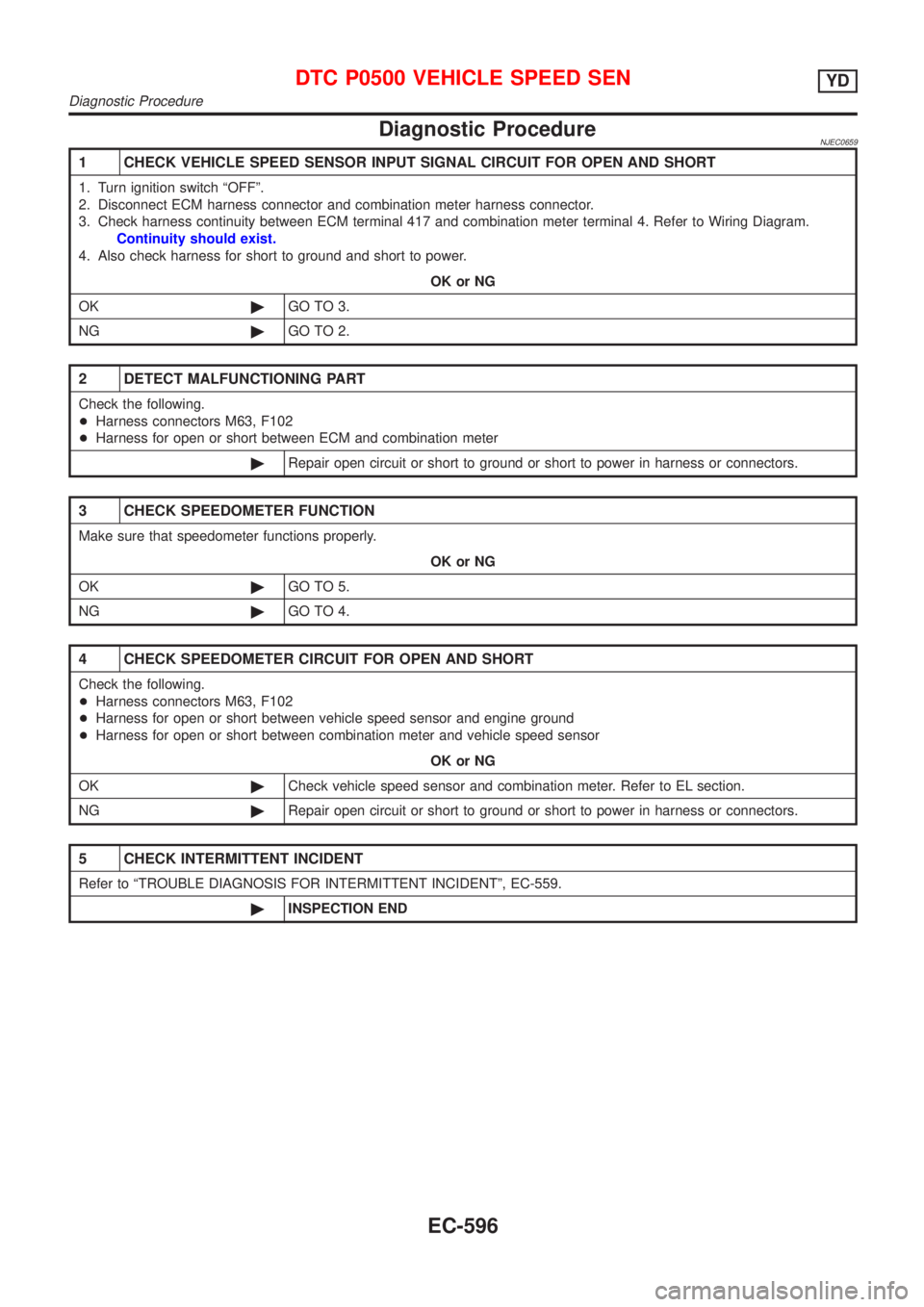
Diagnostic ProcedureNJEC0659
1 CHECK VEHICLE SPEED SENSOR INPUT SIGNAL CIRCUIT FOR OPEN AND SHORT
1. Turn ignition switch ªOFFº.
2. Disconnect ECM harness connector and combination meter harness connector.
3. Check harness continuity between ECM terminal 417 and combination meter terminal 4. Refer to Wiring Diagram.
Continuity should exist.
4. Also check harness for short to ground and short to power.
OK or NG
OK©GO TO 3.
NG©GO TO 2.
2 DETECT MALFUNCTIONING PART
Check the following.
+Harness connectors M63, F102
+Harness for open or short between ECM and combination meter
©Repair open circuit or short to ground or short to power in harness or connectors.
3 CHECK SPEEDOMETER FUNCTION
Make sure that speedometer functions properly.
OK or NG
OK©GO TO 5.
NG©GO TO 4.
4 CHECK SPEEDOMETER CIRCUIT FOR OPEN AND SHORT
Check the following.
+Harness connectors M63, F102
+Harness for open or short between vehicle speed sensor and engine ground
+Harness for open or short between combination meter and vehicle speed sensor
OK or NG
OK©Check vehicle speed sensor and combination meter. Refer to EL section.
NG©Repair open circuit or short to ground or short to power in harness or connectors.
5 CHECK INTERMITTENT INCIDENT
Refer to ªTROUBLE DIAGNOSIS FOR INTERMITTENT INCIDENTº, EC-559.
©INSPECTION END
DTC P0500 VEHICLE SPEED SENYD
Diagnostic Procedure
EC-596
Page 978 of 2493
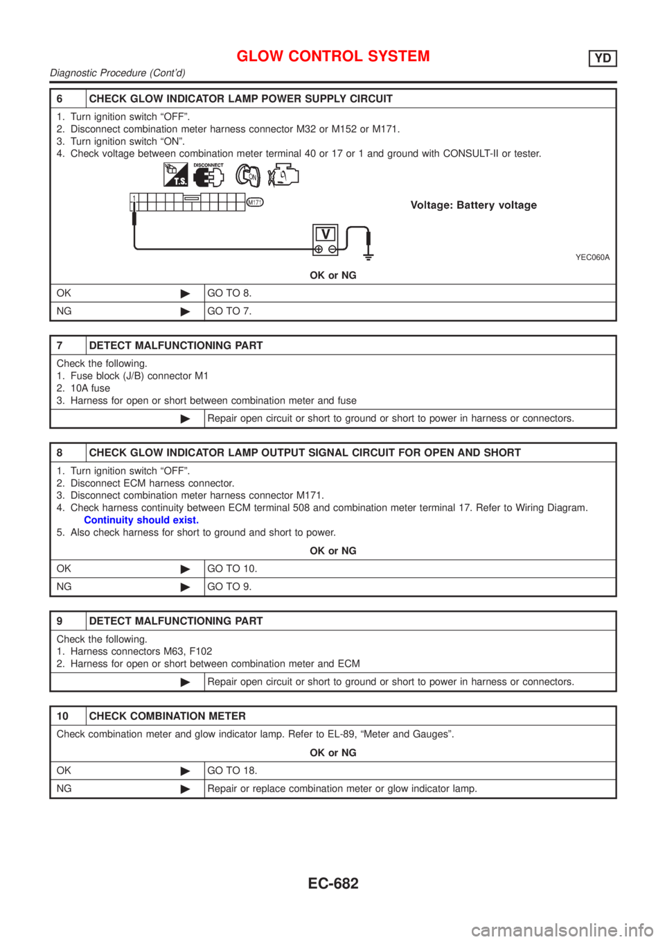
6 CHECK GLOW INDICATOR LAMP POWER SUPPLY CIRCUIT
1. Turn ignition switch ªOFFº.
2. Disconnect combination meter harness connector M32 or M152 or M171.
3. Turn ignition switch ªONº.
4. Check voltage between combination meter terminal 40 or 17 or 1 and ground with CONSULT-II or tester.
YEC060A
OK or NG
OK©GO TO 8.
NG©GO TO 7.
7 DETECT MALFUNCTIONING PART
Check the following.
1. Fuse block (J/B) connector M1
2. 10A fuse
3. Harness for open or short between combination meter and fuse
©Repair open circuit or short to ground or short to power in harness or connectors.
8 CHECK GLOW INDICATOR LAMP OUTPUT SIGNAL CIRCUIT FOR OPEN AND SHORT
1. Turn ignition switch ªOFFº.
2. Disconnect ECM harness connector.
3. Disconnect combination meter harness connector M171.
4. Check harness continuity between ECM terminal 508 and combination meter terminal 17. Refer to Wiring Diagram.
Continuity should exist.
5. Also check harness for short to ground and short to power.
OK or NG
OK©GO TO 10.
NG©GO TO 9.
9 DETECT MALFUNCTIONING PART
Check the following.
1. Harness connectors M63, F102
2. Harness for open or short between combination meter and ECM
©Repair open circuit or short to ground or short to power in harness or connectors.
10 CHECK COMBINATION METER
Check combination meter and glow indicator lamp. Refer to EL-89, ªMeter and Gaugesº.
OK or NG
OK©GO TO 18.
NG©Repair or replace combination meter or glow indicator lamp.
GLOW CONTROL SYSTEMYD
Diagnostic Procedure (Cont'd)
EC-682
Page 1783 of 2493
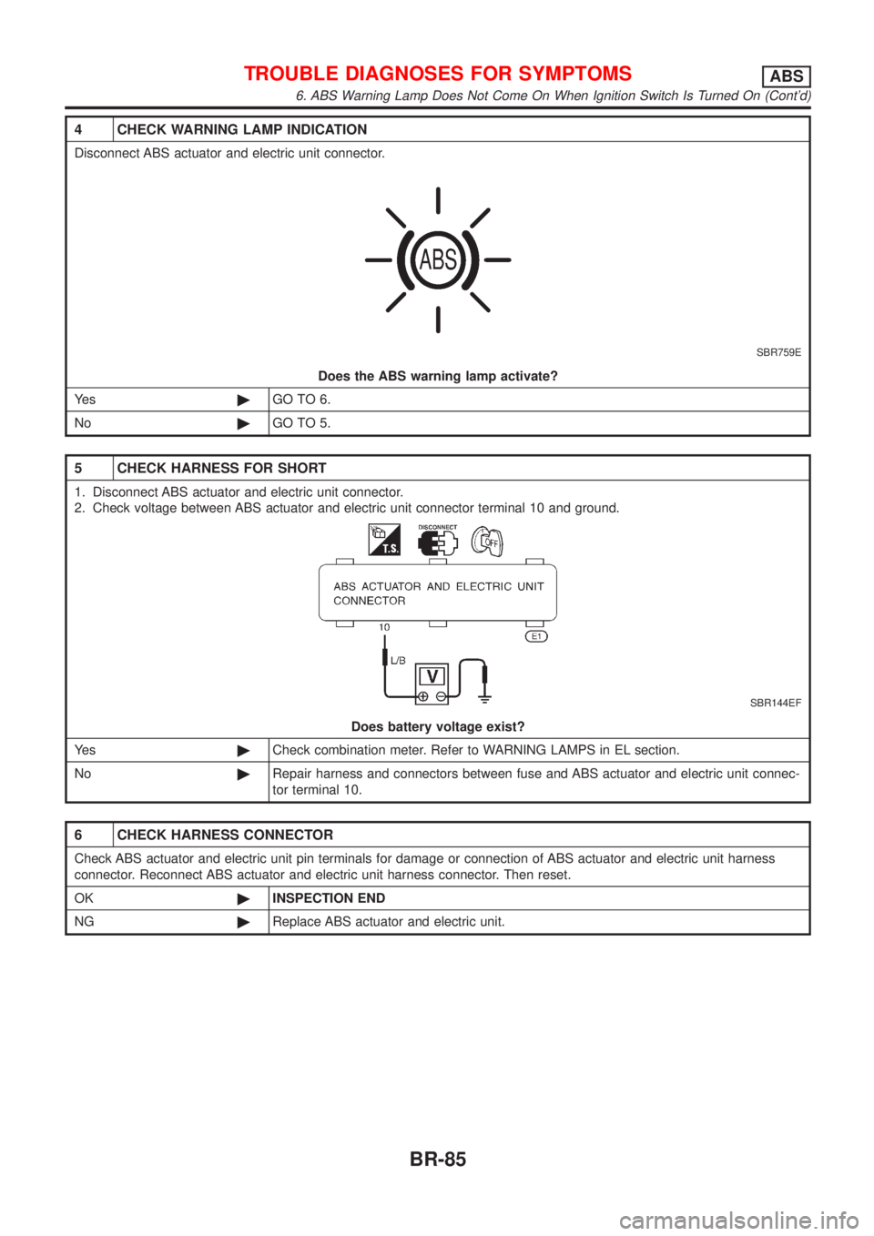
4 CHECK WARNING LAMP INDICATION
Disconnect ABS actuator and electric unit connector.
SBR759E
Does the ABS warning lamp activate?
Ye s©GO TO 6.
No©GO TO 5.
5 CHECK HARNESS FOR SHORT
1. Disconnect ABS actuator and electric unit connector.
2. Check voltage between ABS actuator and electric unit connector terminal 10 and ground.
SBR144EF
Does battery voltage exist?
Ye s©Check combination meter. Refer to WARNING LAMPS in EL section.
No©Repair harness and connectors between fuse and ABS actuator and electric unit connec-
tor terminal 10.
6 CHECK HARNESS CONNECTOR
Check ABS actuator and electric unit pin terminals for damage or connection of ABS actuator and electric unit harness
connector. Reconnect ABS actuator and electric unit harness connector. Then reset.
OK©INSPECTION END
NG©Replace ABS actuator and electric unit.
TROUBLE DIAGNOSES FOR SYMPTOMSABS
6. ABS Warning Lamp Does Not Come On When Ignition Switch Is Turned On (Cont'd)
BR-85
Page 1784 of 2493
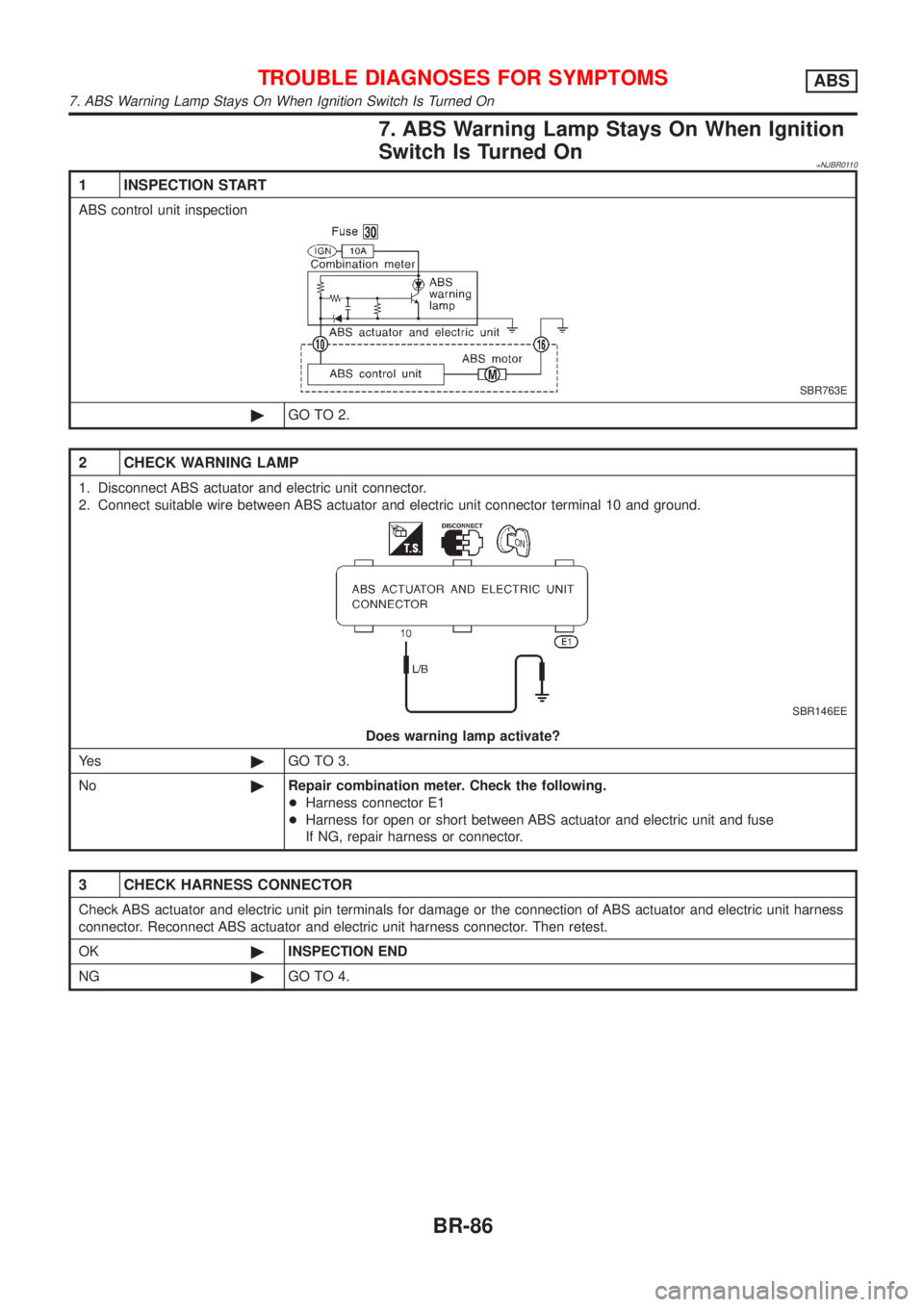
7. ABS Warning Lamp Stays On When Ignition
Switch Is Turned On
=NJBR0110
1 INSPECTION START
ABS control unit inspection
SBR763E
©GO TO 2.
2 CHECK WARNING LAMP
1. Disconnect ABS actuator and electric unit connector.
2. Connect suitable wire between ABS actuator and electric unit connector terminal 10 and ground.
SBR146EE
Does warning lamp activate?
Ye s©GO TO 3.
No©Repair combination meter. Check the following.
+Harness connector E1
+Harness for open or short between ABS actuator and electric unit and fuse
If NG, repair harness or connector.
3 CHECK HARNESS CONNECTOR
Check ABS actuator and electric unit pin terminals for damage or the connection of ABS actuator and electric unit harness
connector. Reconnect ABS actuator and electric unit harness connector. Then retest.
OK©INSPECTION END
NG©GO TO 4.
TROUBLE DIAGNOSES FOR SYMPTOMSABS
7. ABS Warning Lamp Stays On When Ignition Switch Is Turned On
BR-86
Page 2100 of 2493
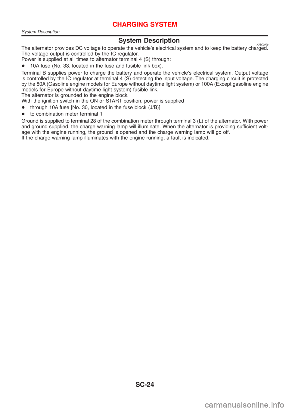
System DescriptionNJSC0009The alternator provides DC voltage to operate the vehicle's electrical system and to keep the battery charged.
The voltage output is controlled by the IC regulator.
Power is supplied at all times to alternator terminal 4 (S) through:
+10A fuse (No. 33, located in the fuse and fusible link box).
Terminal B supplies power to charge the battery and operate the vehicle's electrical system. Output voltage
is controlled by the IC regulator at terminal 4 (S) detecting the input voltage. The charging circuit is protected
by the 80A (Gasoline engine models for Europe without daytime light system) or 100A (Except gasoline engine
models for Europe without daytime light system) fusible link.
The alternator is grounded to the engine block.
With the ignition switch in the ON or START position, power is supplied
+through 10A fuse [No. 30, located in the fuse block (J/B)]
+to combination meter terminal 1
Ground is supplied to terminal 28 of the combination meter through terminal 3 (L) of the alternator. With power
and ground supplied, the charge warning lamp will illuminate. When the alternator is providing sufficient volt-
age with the engine running, the ground is opened and the charge warning lamp will go off.
If the charge warning lamp illuminates with the engine running, a fault is indicated.
CHARGING SYSTEM
System Description
SC-24
Page 2113 of 2493
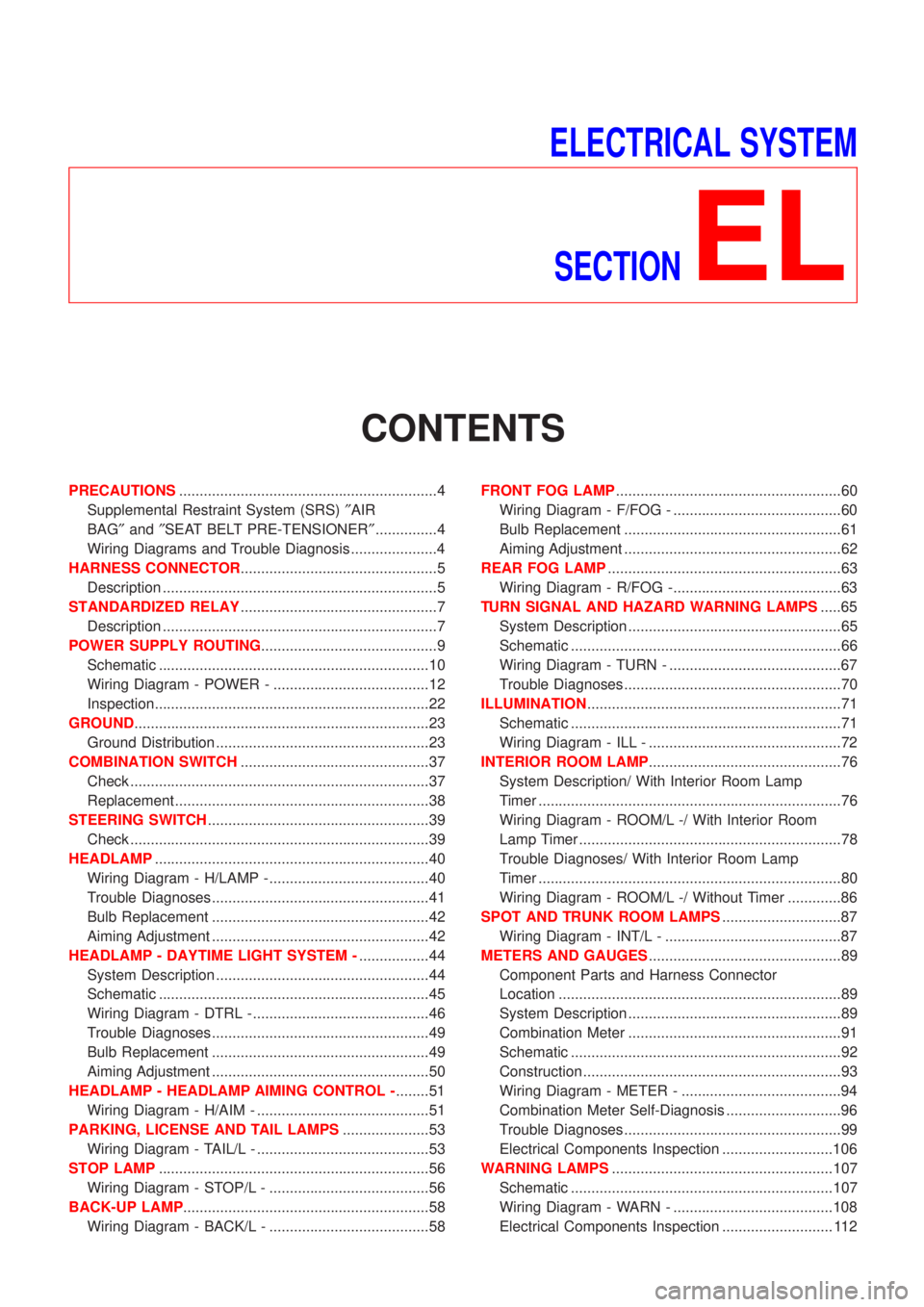
ELECTRICAL SYSTEM
SECTION
EL
CONTENTS
PRECAUTIONS...............................................................4
Supplemental Restraint System (SRS)²AIR
BAG²and²SEAT BELT PRE-TENSIONER²...............4
Wiring Diagrams and Trouble Diagnosis .....................4
HARNESS CONNECTOR................................................5
Description ...................................................................5
STANDARDIZED RELAY................................................7
Description ...................................................................7
POWER SUPPLY ROUTING...........................................9
Schematic ..................................................................10
Wiring Diagram - POWER - ......................................12
Inspection...................................................................22
GROUND........................................................................23
Ground Distribution ....................................................23
COMBINATION SWITCH..............................................37
Check .........................................................................37
Replacement ..............................................................38
STEERING SWITCH......................................................39
Check .........................................................................39
HEADLAMP...................................................................40
Wiring Diagram - H/LAMP -.......................................40
Trouble Diagnoses.....................................................41
Bulb Replacement .....................................................42
Aiming Adjustment .....................................................42
HEADLAMP - DAYTIME LIGHT SYSTEM -.................44
System Description ....................................................44
Schematic ..................................................................45
Wiring Diagram - DTRL - ...........................................46
Trouble Diagnoses.....................................................49
Bulb Replacement .....................................................49
Aiming Adjustment .....................................................50
HEADLAMP - HEADLAMP AIMING CONTROL -........51
Wiring Diagram - H/AIM - ..........................................51
PARKING, LICENSE AND TAIL LAMPS.....................53
Wiring Diagram - TAIL/L - ..........................................53
STOP LAMP..................................................................56
Wiring Diagram - STOP/L - .......................................56
BACK-UP LAMP............................................................58
Wiring Diagram - BACK/L - .......................................58FRONT FOG LAMP.......................................................60
Wiring Diagram - F/FOG - .........................................60
Bulb Replacement .....................................................61
Aiming Adjustment .....................................................62
REAR FOG LAMP.........................................................63
Wiring Diagram - R/FOG -.........................................63
TURN SIGNAL AND HAZARD WARNING LAMPS.....65
System Description ....................................................65
Schematic ..................................................................66
Wiring Diagram - TURN - ..........................................67
Trouble Diagnoses.....................................................70
ILLUMINATION..............................................................71
Schematic ..................................................................71
Wiring Diagram - ILL - ...............................................72
INTERIOR ROOM LAMP...............................................76
System Description/ With Interior Room Lamp
Timer ..........................................................................76
Wiring Diagram - ROOM/L -/ With Interior Room
Lamp Timer ................................................................78
Trouble Diagnoses/ With Interior Room Lamp
Timer ..........................................................................80
Wiring Diagram - ROOM/L -/ Without Timer .............86
SPOT AND TRUNK ROOM LAMPS.............................87
Wiring Diagram - INT/L - ...........................................87
METERS AND GAUGES...............................................89
Component Parts and Harness Connector
Location .....................................................................89
System Description ....................................................89
Combination Meter ....................................................91
Schematic ..................................................................92
Construction ...............................................................93
Wiring Diagram - METER - .......................................94
Combination Meter Self-Diagnosis ............................96
Trouble Diagnoses.....................................................99
Electrical Components Inspection ...........................106
WARNING LAMPS......................................................107
Schematic ................................................................107
Wiring Diagram - WARN - .......................................108
Electrical Components Inspection ........................... 112
Page 2153 of 2493
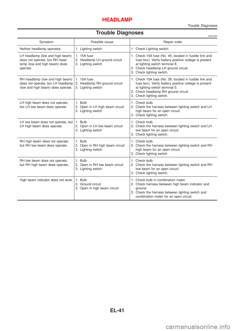
Trouble DiagnosesNJEL0202
Symptom Possible cause Repair order
Neither headlamp operates. 1. Lighting switch 1. Check Lighting switch.
LH headlamp (low and high beam)
does not operate, but RH head-
lamp (low and high beam) does
operate.1. 15A fuse
2. Headlamp LH ground circuit
3. Lighting switch1. Check 15A fuse (No. 40, located in fusible link and
fuse box). Verify battery positive voltage is present
at lighting switch terminal 8.
2. Check headlamp LH ground circuit.
3. Check lighting switch.
RH headlamp (low and high beam)
does not operate, but LH headlamp
(low and high beam) does operate.1. 15A fuse
2. Headlamp RH ground circuit
3. Lighting switch1. Check 15A fuse (No. 39, located in fusible link and
fuse box). Verify battery positive voltage is present
at lighting switch terminal 5.
2. Check headlamp RH ground circuit.
3. Check lighting switch.
LH high beam does not operate,
but LH low beam does operate.1. Bulb
2. Open in LH high beam circuit
3. Lighting switch1. Check bulb.
2. Check the harness between lighting switch and LH
high beam for an open circuit.
3. Check lighting switch.
LH low beam does not operate, but
LH high beam does operate.1. Bulb
2. Open in LH low beam circuit
3. Lighting switch1. Check bulb.
2. Check the harness between lighting switch and LH
low beam for an open circuit.
3. Check lighting switch.
RH high beam does not operate,
but RH low beam does operate.1. Bulb
2. Open in RH high beam circuit
3. Lighting switch1. Check bulb.
2. Check the harness between lighting switch and RH
high beam for an open circuit.
3. Check lighting switch.
RH low beam does not operate,
but RH high beam does operate.1. Bulb
2. Open in RH low beam circuit
3. Lighting switch1. Check bulb.
2. Check the harness between lighting switch and RH
low beam for an open circuit.
3. Check lighting switch.
High beam indicator does not work. 1. Bulb
2. Ground circuit
3. Open in high beam circuit1. Check bulb in combination meter.
2. Check harness between high beam indicator and
ground.
3. Check the harness between lighting switch and
combination meter for an open circuit.
HEADLAMP
Trouble Diagnoses
EL-41
Page 2182 of 2493
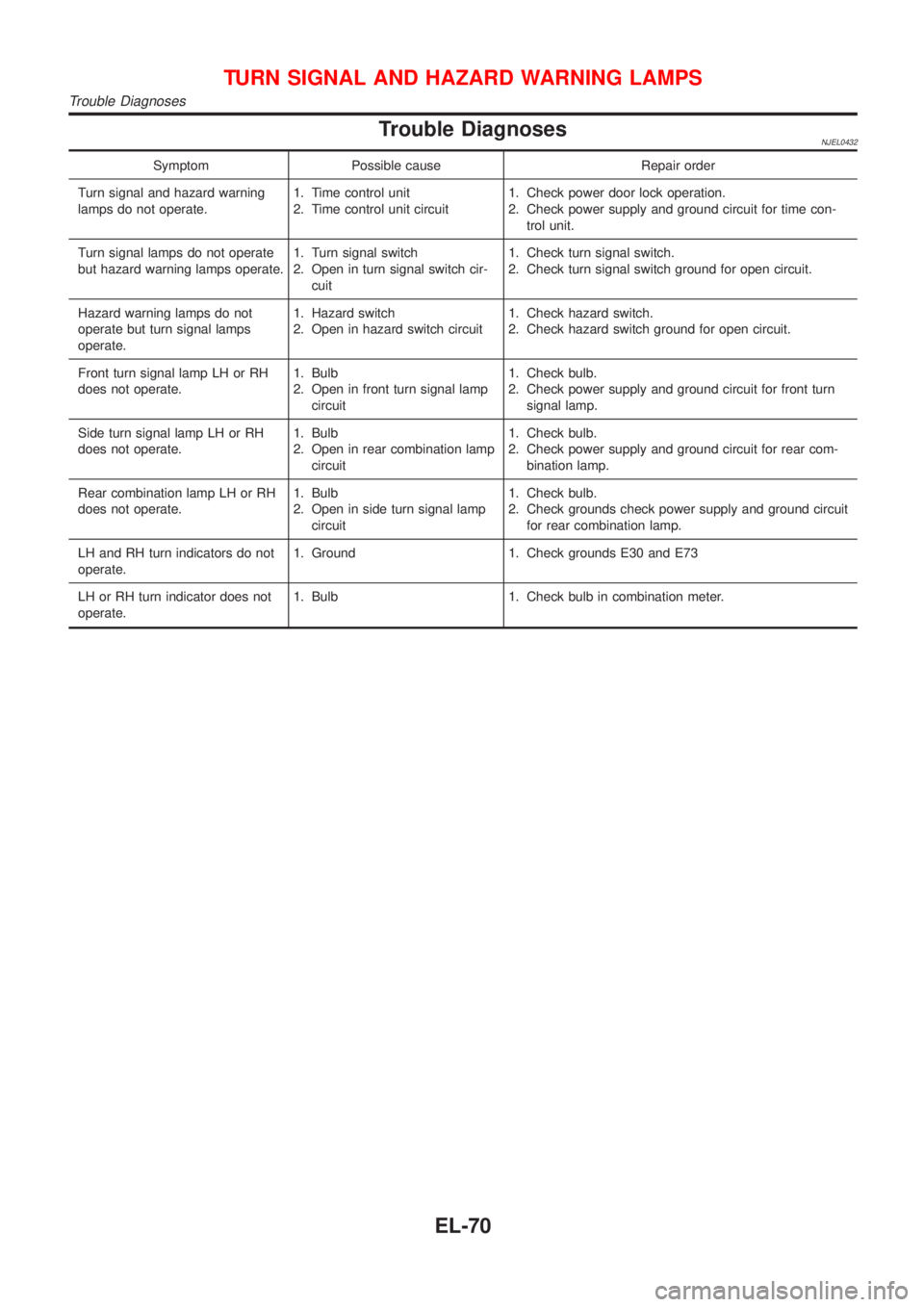
Trouble DiagnosesNJEL0432
Symptom Possible cause Repair order
Turn signal and hazard warning
lamps do not operate.1. Time control unit
2. Time control unit circuit1. Check power door lock operation.
2. Check power supply and ground circuit for time con-
trol unit.
Turn signal lamps do not operate
but hazard warning lamps operate.1. Turn signal switch
2. Open in turn signal switch cir-
cuit1. Check turn signal switch.
2. Check turn signal switch ground for open circuit.
Hazard warning lamps do not
operate but turn signal lamps
operate.1. Hazard switch
2. Open in hazard switch circuit1. Check hazard switch.
2. Check hazard switch ground for open circuit.
Front turn signal lamp LH or RH
does not operate.1. Bulb
2. Open in front turn signal lamp
circuit1. Check bulb.
2. Check power supply and ground circuit for front turn
signal lamp.
Side turn signal lamp LH or RH
does not operate.1. Bulb
2. Open in rear combination lamp
circuit1. Check bulb.
2. Check power supply and ground circuit for rear com-
bination lamp.
Rear combination lamp LH or RH
does not operate.1. Bulb
2. Open in side turn signal lamp
circuit1. Check bulb.
2. Check grounds check power supply and ground circuit
for rear combination lamp.
LH and RH turn indicators do not
operate.1. Ground 1. Check grounds E30 and E73
LH or RH turn indicator does not
operate.1. Bulb 1. Check bulb in combination meter.
TURN SIGNAL AND HAZARD WARNING LAMPS
Trouble Diagnoses
EL-70
Page 2201 of 2493
Component Parts and Harness Connector
Location
NJEL0441For details, refer to ªELECTRICAL UNIT LOCATIONº (EL-319) and
ªHARNESS LAYOUTº (EL-324).
System DescriptionNJEL0442UNIFIED CONTROL METERNJEL0442S01+Speedometer, odo/trip meter, tachometer, fuel gauge and water temperature gauge are controlled totally
by control unit built-in combination meter.
+Digital meter is adopted for odo/trip meter.*
*The record of the odo meter is kept even if the battery cable is disconnected. The record of the trip meter
is erased when the battery cable is disconnected.
+Odo/trip meter segment can be checked in diagnosis mode.
+Meter/gauge can be checked in diagnosis mode.
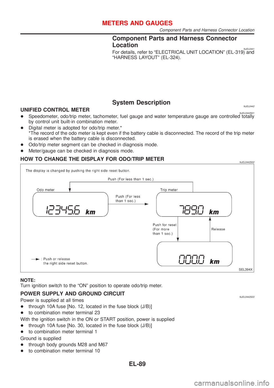
HOW TO CHANGE THE DISPLAY FOR ODO/TRIP METERNJEL0442S02
SEL394X
NOTE:
Turn ignition switch to the ªONº position to operate odo/trip meter.
POWER SUPPLY AND GROUND CIRCUITNJEL0442S03Power is supplied at all times
+through 10A fuse [No. 12, located in the fuse block (J/B)]
+to combination meter terminal 23
With the ignition switch in the ON or START position, power is supplied
+through 10A fuse [No. 30, located in the fuse block (J/B)]
+to combination meter terminal 1
Ground is supplied
+through body grounds M28 and M67
+to combination meter terminal 10
METERS AND GAUGES
Component Parts and Harness Connector Location
EL-89